Modelling and Simulation of Dc to Ac Converter
for Renewable Energy Source Using Simulink
M. Sujith1, J. Asha2
1 Department of Electrical and Electronics Engineering, IFET College of Engineering, Villupuram 2Dean Placement, IFET College of Engineering, Villupuram
Abstract: This paper deals with modeling and simulation of DC-AC converter for Renewable Energy Source. DC from the solar cell is stepped up using a Boost converter. The output of the Boost converter is converted in to three-phase AC using three-phase bridge inverter. Simulation is done with normal load and additional load and the results are presented. The sag in voltage due to additional load is compensated by increasing the output voltage from the Boost converter. The system has advantages like reduced hardware and voltage regulation capability.
Index Terms—distributed generation, photovoltaic, inverter
I. INTRODUCTION
In 2004, United States consumed nearly 20 million barrels of petroleum per day with daily production averaged only 7 million barrels [1]. So US depend on foreign imports of fuel. With high price on gasoline and increased demands on clean energy, renewable energy based generation is more popular. Renewable energy includes solar energy, wind energy and fuel cells etc. These energy sources are renewable and utilization of these energy sources creates zero or little emissions. Also distributed generation (DG) systems using renewable energy increase the reliability. Now renewable energy systems are relatively expensive and hence the cost is higher than fossil fuel. So renewable energy sources captured a small share of the total energy market [2]. However, with the development of technology, the cost of renewable energy is decreasing steadily and it will become as or more cost effective than fossil fuel in the future Technology is the key to increase the market share of renewable energy power generation. For renewable energy systems, power electronics play a vital role. Sometime they are the most expensive part of the system. Reducing cost, increasing efficiency and improving reliability of power electronics and electric machines are the technical challenges facing wider implementation of renewable energy power generation [3].
II.RENEWABLEENERGYSOURCES
Renewable energy sources derive their energy from existing flow of energy, from on-going natural processes such as sun, wind, flowing water and geothermal heat flows. The most feasible alternative energy sources include solar, fuel cell and wind.
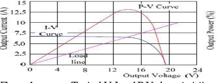
A. Solar Power
[image:2.612.199.420.634.718.2]temperature and radiation. The intersection of the load line with the photovoltaic V-I characteristics is the operating point. In practice PV models are first cascaded then paralleled to form PV array, thus to meet the voltage and power requirement.
A. FuelCell
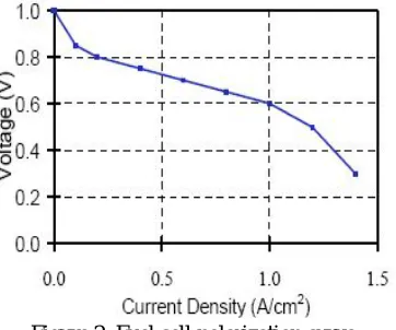
[image:3.612.218.399.233.384.2]A fuel cell is a device that generates electricity by a chemical reaction. For fuel cell, hydrogen is the basic fuel. Hydrogen is produced from natural gas and renewable sources. Hydrogen is the most abundant element, the simplest chemical fuel that makes a highly efficient, clean burning energy carrier. Phosphoric acid fuel cells are commercially used to generate electricity in 200KW capacities. The fuel cells voltage and power is determined by two factors. First the rate at which hydrogen flows through the fuel cell [7]. Second the amount of current drawn by the inverter. Thus, by controlling the amount of current drawn by the inverter, the fuel cell voltage and power can be controlled [8]. Fig. 2 shows that the fuel polarization curve.
Figure 2. Fuel cell polarization curve
B. WindEnergy
Wind is intermittent resource and variable and unpredictable over even a day’s time. Wind occurs as a direct result of differential solar heating of the atmosphere. The differences depend on altitude, land and sea, time of year, time of day etc. and when combined with the rotation of the earth and local geographical features produce an extremely complex distribution of wind strength and direction over both time and space.
The power in the wind is a function of its speed and air density. Density of air decreases with increasing temperature and increasing altitude. The most important factor for the amount of wind energy is the wind speed. The power curve of a wind is a graph that indicates how large the electrical power output will be for the turbine at different wind speeds.
The wind turbines use the kinetic energy of the wind and convert that energy in to mechanical energy, which in turn can be converted in to electricity by means of a generator. There are two types of wind turbines: the horizontal axis variety and the vertical axis design. The horizontal axis variety is currently the most practical.
In the past years, the amount of energy produced by wind driven turbines has increased hugely due to the growing technologies of turbine. Thus making wind power economically compatible with conventional sources of energy [6]. The above literature does not present simulink model of closed loop DC-AC converter system. The aim of this work is to develop a model for DC-AC converter.
III. BASICSOFPCSFORRENEWABLEENERGYSOURCES
Figure 3.a Configuration using a single PWM Inverter
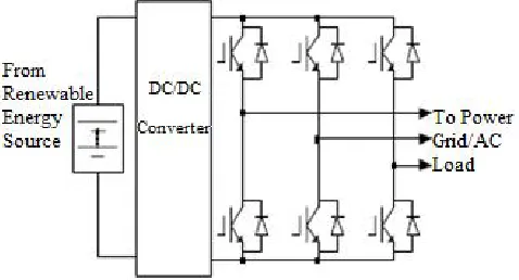
Figure 3.b Configuration using a DC/DC Converter and a PWM Inverter
The traditional voltage source PWM inverter is used in both figures 3a and 3b. The inverter is used to convert DC power to AC voltage required by the load and power grid. The DC power is from fuel cell, PV panel in solar power, or rectified turbine generator in wind power. The output voltage that the inverter can produce is always lower than the available DC voltage. This voltage buck nature of the traditional voltage-source inverter bears many drawbacks:
For DG systems, the required AC output voltage demands a minimum DC source voltage, thus more cells (solar or fuel cells) have to be stacked in series to provide the minimum DC voltage. The connection cost and the cost associated with HV installations are high[4].
A minimum DC voltage or DCDC voltage boost stage is needed and components have to be oversized and become less efficient. Many power sources, such as PV panels, fuel cells, wind turbine generators, have a wide voltage change range with load. The inverter has to be rated according to the maximum voltage and maximum current. For a required output power, the inverter thus has to be rated twice the output power to cope with the voltage change range of 1:2 In order to overcome the drawbacks of traditional voltage source inverter, a DC/DC boost converter is added to boost voltage as shown in figure 3 b. This configuration greatly reduces the requirements and costs of the energy source. This positively impacts the inverter current rating and hence cost of the whole system. However, there are still some disadvantages:
A. Because of two stage configurations, the power is processed through two stages: DC-DC boost stage and DC-AC inversion stage which reduces the power conversion efficiency.
B. As more components are used in this configuration reliability is reduced.
C. The boost stage increases system size/weight because of the additional heat sinks.
Hence both configurations have limitations which contribute high cost. New technologies to reduce the cost, size and increase the efficiency and reliability have been always the research topic of power electronics. In this paper, we look in to an inverter topology, DCAC converter and present its applications to power conditioning and utility interface for renewable energy sources.
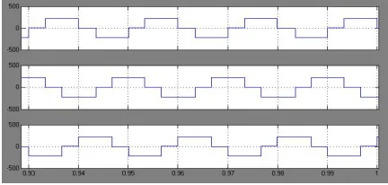
inverter. The output contains three voltages displaced by 120 degree. The phase currents are shown in Figure 4e. Output power supply to the load is shown in Figure 4f. The variation of output voltage in duty cycle is given in table 1. The corresponding graphs are shown in figure 4g.DC-AC converter with additional load is shown in figure 5a. Output of boost converter is shown in
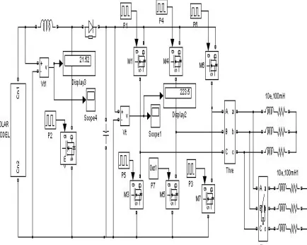
[image:5.612.199.412.300.404.2]Figure 4.a.DC-AC converter using solar cell
Figure 4.b. Output voltage of solar cell
Figure 4.c. Output voltage of boost converter
[image:5.612.199.415.434.575.2] [image:5.612.197.413.609.712.2]Figure 4.e. Output inverter phase current
Fig4.f. Output power supply to the load
Duty cycle Boost
voltage
Po=V*I (W)
Po=V*I*C OSQs(W)
0.75 167 216 313
0.8 190 282 410
0.85 215 360 522
9.0 225 388 564
Table1.Variation of output voltage
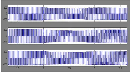
DC-AC converter with hybrid generation source is shown in figure 5a. The voltage decreases due to the addition of extra load. Three phase line voltages are shown in B
[image:6.612.196.413.529.702.2]Figure 5.b.Output of boost converter
[image:7.612.196.414.334.457.2]Figure 5.c.RMS value of inverter voltage
Figure 5.d.3-phase line voltage\
V. CONCLUSION
DC-AC converter with solar cells and hybrid generation system are modeled using mat lab simulink. These models are successfully used for simulation studies. The advantage of the boost converter at the input is that it has reduced hardware. The hybrid generation system is capable of maintaining constant voltage at the output. The simulation results with single source and dual source systems are presented. The simulation results are in line with the predictions.
REFERENCES
[1]. Frede Blaabjerg, Zhe hen,S.B.Kjaer, “Power electronics as efficiency interface in dispersed power generation systems” IEEE Trans.on Power Electronics.Oct 2004.
[2]. F.Z.Peng, “Z-Source Inverter”, IEEE Transactions on industry applications” APR 2003.
[3]. Miaosen Shen, Jin Wang, Alan Joseph,FangZ.Peng, Leon M Tolbert and Donald J Adams, “Maximum constant boost control of the Z-Source Inverter” in proc IEEE IAS’04
[4]. Y.Hung; M.Shen; F.Z.Peng; J.Wang “A Z-Source Inverter for residential Photovoltaic systems” IEEE Trans on Power Electronics .Nov 2006.
[5]. Shen.M, Joseph.A,Wang.J,Peng.F.Z, Adams.D.J “Comparison of traditional inverers and Z-Source Inverter”. IEEE Power Electronics specialist conference.Jun’05
[6]. Kent Holland, Miaosen Shen, F.Z.Peng “Z-Source Inverter control for traction drive of fuel cell-battery hybrid vehicles” IEEE Industry Applications Conference Oct 2005