5
X
October 2017
Implementation of Error Resilience Video
Transmission Over Noisy Channel Using Wimax
Adarsha.M1,
1
CMR Institute of Technology, Bangalore,Karnataka, India
Abstract: This project presents the simulation and performance analysis of Wi-MAX (Worldwide Interoperability for Microwave Access) system along with efficient wireless channels using real time video transmission. When the compressed video bit-stream is transmitted over the error-prone channels such as a packet lossy network, it is possibly corrupted by the channel noise. All information contained in the lost packets will not be available at the decoder and thus the video reconstruction is of a poor quality. Many error resilience techniques such as resynchronization marker insertion and forward error correction (FEC) have been proposed to add side information in the coded bit-stream at the encoder side to make it more resilient to channel errors.H.264/AVC also employs several new error resilience tools to combat the channel errors. However, they still cannot guarantee to compensate the channel errors with good reconstruction quality. To reduce the quality degradations and improve the video quality, error concealment techniques are used at the decoder side as a post-processing module.
Keywords: Wi-Max, Channel Noise, Forward Error Correction, Bit error rate, PSNR.
I. INTRODUCTION
In the last decade, there has also been a rapid development in the digital video compression filed. Using new compression algorithms with high compression rates, digital video can provide superior quality with low bandwidths over its analog counterpart. With the addition of low and very-low bit rate coding algorithms, video transmission over wire-line channels is now a mature area. Combination of advances in digital video compression and digital wireless communications resulted in a new service area called video over wireless. Potential applications such as HDTV and picture-phones attracted attentions, and now are under rapid development. Services related to video transmission over wireless channels are expected to grow exponentially in the near future. Due to the proliferation of multimedia on WWW and the emergence of broadband wireless network, wireless video communication has received great interests from both industry and academy. However, the characteristics of wireless channel impose new problems to video transmission.
II. WIMAX SYSTEM MODELING FOR VIDEO TRANSMISSION
The main objective of this paper is to build up the real time model for the Wi-MAX system along with the suitable wireless channel compatible to various atmospheric conditions for the signal propagation. The model discussed in the research paper is built on QAM modulation scheme and OFDM technique based on the platform of Mat lab R2009a, running on Windows XP SP2. Mat lab Simulink includes all the mandatory function blocks as specified by the standard documents. The model shown in comprises of transmitter, receiver and channel which is AWGN channel in the first case. The encoder of the Wi-MAX system is the combination of Reed Solomn (RS) code as an outer code and Convolution code (CC) as an inner code.
The encoded baseband data is modulated by means of QAM which is applied for OFDM process as the physical layer of Wi-MAX system is made up of OFDM. In OFDM process, the in phase and quadrature phase components of the symbols will undergo through the process of IFFT so that requirement of effective bandwidth can be made approximately half without any inter symbol interference.
Figure.1 WIMAX system Modeling for video transmission
For this reason FEC is characterized as effective when the redundancy is sufficient to recover the lost data, ineffective when the redundancy is little to recover the lost data and inefficient when the redundancy is high for the lost data. To provide best performance for the streaming application and the network, it is important to determine, in real time, the proper amount of redundant information according to the loss behavior of the network. However it not clears how to choose optimal redundancy given the constraints mentioned above at any given point in time.
III. CHANNEL CODING
A. Reed-Solomon Encoder And Decoder
Three different code word lengths are used for encoding the HRPDU frame: the first 48 octets of the header are encoded with a RS (56,48) code, the remaining 44 HRP header octets are encoded with a RS (52,44) code and the payload octets are encoded using a RS(224,216) code.
The main blocks of the Reed-Solomon encoding block are two Reed-Solomon encoders working in parallel encoding simultaneously the upper branch data and the lower branch data. The implemented RS encoder blocks can perform all three encoding schemes. The additional blocks are used for splitting, routing the header data to both RS encoders and appending four null symbols to the portion of the header that is encoded using the RS (52, 44) code.
B. External Interleaver And External Deinterleaver
The external-Inter-leaver block uses two Inter-leavers, one for the upper branch data and another for the lower branch data. Each Inter-leaver distributes data to four convolutional encoders. The internal structure of the External-Inter-leaver block in represented in Figure. 2.
Figure.2 External-Inter-leaver block internal structure (transmitter)
The main blocks are the upper and lower branch Inter-leaver blocks. The additional blocks are used to allow the use of just the upper interleaver block as required for processing the HRP header and data for HRP modes 5 and 6. For all HRP modes the depth is defined to be four; the depth used in the HRP header is two. The mat lab function sfunct_outerinterleaver.m groups depth × N sets of octets and implements (13) for depths 2 and 4.In the receiver the reverse operation is implemented by the outer de-inter-leaver blocks[2].
C. Convolutional Encoder And Decoder
After being interleaved the data is encoded by a convolutional code. The encoder block is composed by eight convolutional encoders in parallel, four for the data of each inter-leaver block.
The decoding operation on the receiver is done by eight Viterbi decoders in parallel. The Mat lab function that implements the convolutional decoder, sfunct_viterbi_decoder.m, uses the Mat lab built in function, vitdec.m, to perform the DE codification and data puncturing. This block is prepared to handle soft decoding in which the logic values “0” and “1” are represented by a value between 0 and 2nbits-1, where nbits is the number of bits in each soft bit.
IV. RESULT ANALYSIS AND DISCUSSION
The FEC coder supplements each segment with the same number of parity bits. RS Coding is used for this case. The second scheme is the outcome of the sensitivity analysis experiments. In this scheme, a stronger FEC is applied to the first frame (the first I frame) as the important data is found in it. Hence Convolutional coding is used for the rest inter frames. The main aim of the algorithm is to strengthen the video stream against most possible error cases and also reduce the percentage of the overhead bits arising because of FEC coding.
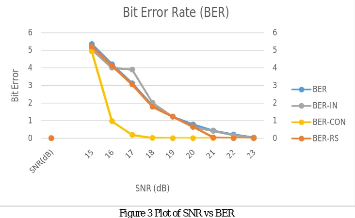
Table. I SNR vs BER Values for Different TechniquesBit Error Rate (BER)
SNR(dB) Without
Channel Coding Reed Solomon Encoding Convolutional Interleaving Convolutional Encoder
15 5.354 5.220 5.0523 4.95
16 4.21 4.122 4.005 0.965
17 3.120 3.053 3.9 0.1856
18 1.85 1.789 2.02 0.0095
19 1.225 1.234 1.21 0.001
20 0.785 0.650 0.632 0
21 0.432 0.0445 0.407 0
22 0.215 0.0043 0.1632 0
23 0.045 0 0.0056 0
The strength of the FEC can be varied based on system average BER. The simulation was also carried out by varying the signal-to-noise ratio of AWGN Channel using different FEC techniques like combination of RS and Convolutional was adopted to see the effect of signal-to-noise ratio on bit error rate. It was observed that if the number of redundant bits is increased or the convolutional code can correct more errors, then the bit error rate is achieved at lower signal-to-noise ratio. But the disadvantage is that the percentage of the overhead bits is increased.
Figure 3 Plot of SNR vs BER .
The project concludes that the transmitted errors recovery with Convolution Encoder gives better results as compared to other technique and by seeing at the results we can say that convolutional encoder provide better quality of video at 5 dB lesser than all other techniques. 0 1 2 3 4 5 6 0 1 2 3 4 5 6 B it E rr o r SNR (dB)
Bit Error Rate (BER)
BER
BER-IN
BER-CON
[image:5.612.124.490.443.668.2]Table. II SNR vs PSNR Values For Different Techniques PSNR (dB)
SNR(dB) Without
Channel Coding Reed Solomon Encoding Convolutional Interleaving Convolutional Encoder
15 -47.85 -47 -46.01 -41.5
16 -44.65 -45.23 -45 -32.5
17 -42.50 -41.5 -42 27
18 -40.50 -41 -41.5 42
19 -40.50 -40.5 -40 Inf
20 -40.63 -38 -38 Inf
21 -37.5 17.29 -36 Inf
22 -34.83 35.6 -29 Inf
23 22.57 Inf Inf Inf
Figure.4 Plot of SNR vs PSNR
V. CONCLUSION AND FUTURE WORK
In this Project, we tried to provide better video quality for transmission over wireless channels. Owing to the applied compression, H.264 is very vulnerable to bit errors due to fading on radio channels. Hence extraneous effort is needed to control error in the video stream. The bit sensitivity experiment was performed to find out the effect of each bit to the overall PSNR value of the video. The important points to note from the experiments were:
A. An error in a later part of a frame is less important than one occurring before (in spatial domain). This effect is attributed to the resynchronization procedure.
B. The first Intra frame has been found to be important for the overall video quality.
C. The most important segments in a frame are the macro block header bits (CBPY). The next important values correspond to the
coefficients. -60 -40 -20 0 20 40 60 80 100 120 P SN R SNR (DB)
SNR(dB) vs PSNR
FEC scheme has been implemented to control error in the video stream as compressed video stream is fragile in the presence of error. FEC of different strength is also used to observe the effect of SNR on BER. The strength of the FEC code provides another degree of freedom in improving quality. Also from the bit sensitivity analysis we found that the first intra-frame is most important for the overall video quality. So we go for a stronger FEC for the intra-frame as other frames are generated using the first intra frame.
D. Beyond BER of 0.5%, the loss of synchronization problem creeps in which results in loss of video quality.
E. When FEC codes of different strength was used, it was found that the code which can correct more errors gives the same bit
error rate at lower signal-to-noise ratio but the redundancy is increased.
F. When we applied RS coding to the first frame, more redundancy was produced as compared to the other scheme.
G. It is also stable at higher bit error rate because weak bits are well protected. The new algorithm is stable till BER of 0.8% as compared to 0.5% of full FEC using BCH (63, 51, 2).
In this Project we have considered the importance of luminance components only. We can extend this work for chrominance components also video transmission was considered with AWGN channel in this work. We want evaluate the performance of same system using Rayleigh and Racian channels in the near future.
VI. ACKNOWLEDGMENT
The successful completion of task would be incomplete without complementing those who made it possible and whose guidance and encouragement made my efforts successful.
I take great pleasure in expressing my sincere thanks to Dr. Sanjay Chitnis, Principal CMRIT-Bangalore for his valuable support. I would like to express my sincere gratitude and thanks Mr.PrashanthGantla, Scientific Assistant, Istrac/ISRO for his relentless support and guidance.
Last but not the least, I take this opportunity in expressing my gratitude and respect to all those who directly or indirectly helped and encouraged me during this work.
REFERENCES
[1] The WiMAX 802.16e Physical Layer Model Muhammad Nadeem Khan, SabirGhauri University of the West England, United Kingdom. [2] Rijkse, Karel,”H.264: Video Coding for Low-Bit-Rate Communication”, IEEE Communication Magazine. Vol. 34,(December 1996): pp.42-45.
[3] Dufaux,F. and Moscheni, F.,“Motion Estimation Techniques for Digital TV: A Review and a New Contribution”. Proc.IEEE.Vol.83, no.6, (June 1995):pp.858-876
[4] Wang, y., Ostermann,j., and Zhang Ya-Qin. Video Processing and Communications. Upper Saddle River, New jersey: Prentice Hall,2002
[5] 2012 International Conference on Communication Systems and Network Technologies. Implementation and PerformancChannels in WiMAX using Image and Speech Transmissio
[6] 2012 International Conference on Communication Systems and Network Technologies mobile and wireless network. An OFDM Based System forTransmission of JPEG2000 Images Using Unequal Power Allocatio
[7] ArohBarjatya,”Block Matching Algorithms for Motion Estimation”.IEEE. Student Member, (April 2004).
[8] Jain, Jaswant, and Jain, Anil,”Displacement Measurement and Its Application in Interframe Image Coding”.IEEE Transactions on Communications.Vol.COM-29, No.12 (December 1981)
[9] Wu, Siu-Wai and Gersho, Allen,”Joint Estimation of Forward and Backward Motion Vectors for Interpolative Prediction ofVideo”.IEEE Transactions [10] Chen,Lei and Lee,Chung-wei,”Multi-level secure video streaming Over SRTP”.43rd ACM Southeast Conference.(March18-20,2005).
[11] Muhammad Nadeem Khan, SabirGhauri, “The WiMAX802.16e Physical Layer Model”, IEEE Xplore. [12] AbdulrahmanYarali, BwangaMbula, Ajay Tumula, “WiMAX: A Key to Bridging the Digital Divide”, IEEE Xplore.
[13] Chengshan Xiao, Jingxian Wu, Sang-Yick Leong and Yahong Rosa Zheng (2004), A Discrete-Time Model for Triply Selective Mimo Rayleigh Fading [14] Channels, IEEE Transactions On Wireless Communications, Vol. 3, No. 5, pp.1678 – 1688, ISSN: 1536-127 802.16™, IEEE Standard for Local and

![(4R) 4 Benzyl 3 {(4S) 4 chloro 4 [(S) 2,2 dimethyl 1,3 dioxolan 4 yl]butanoyl} 1,3 oxazolidin 2 one](data:image/gif;base64,R0lGODlhAQABAIAAAP///wAAACH5BAEAAAAALAAAAAABAAEAAAICRAEAOw==)