©IJRASET 2015: All Rights are Reserved
862
Efficient
Implementation of
2D - DWT for Video
Compression
Using Bit Parallel Architecture
U.Sowmya
Department of Electronics and Communication Engineering, R.M.K. College of Engineering and Technology
Abstract— The Discrete wavelet transform (DWT) has gained widespread acceptance in signal processing and image compression. Because of their inherent multi-resolution nature, wavelet-coding schemes are especially suitable for applications where scalability and tolerable degradation are important. Most of the DWT architectures utilize pipelining and combinational logic design to reduce power and chip size. However those designs don’t meet acceptable power. Image memories and intermediate storage are major drawbacks associated with power consumption. By replacing this issue with common memory architecture for both intermediate and default memory storage by using ASIP.
Index Terms - Discrete Wavelet Transform (DWT), Application Specific Instruction Processor (ASIP)
I. INTRODUCTION
Discrete wavelet transform is mainly used in sub-band coding. It is a fast computation in wavelet transform and its computation time is faster. The discrete wavelet transform is well known the for its application in image and video compression, fractal analysis, texture discrimination, computer graphics, and bioinformatics, etc. The discrete wavelet transform is used both in image and video compression. The discrete wavelet transform can be classified as 1-D and 2-D. The 1-D discrete wavelet transform is mainly used for signal processing and 2-D discrete wavelet transform is mainly used for image processing. Due to its remarkable advantage over the discrete cosine transform in image compression, 2-D DWT has been accepted as standard compression technique. For full image transmission more area and power is required. So DCT and DWT is mainly used for image compression, among these DCT is mainly used because in DCT hardware design is simple, easy to re-construct. In DWT area complexity is more due to buffer, PDP increases which in turn increases speed in-order to overcome this, buffer is removed. Due to single array processing DWT requires more frames and buffer that increase filter bank size, lead to increase in PDP. DWT are mostly of two types convolution based and lifting based. The lifting scheme of computation of DWT become more popular over convolution based scheme for its computational complexity, lifting based wavelet decomposition has many useful properties like symmetric forward and inverse transform instead of computation and integer-integer wavelet transform. Lifting based computation involves much less number of multipliers, adders, and storage elements compared to convolution based algorithm. The lifting based scheme is more suitable for low-complexity hardware implementation of DWT. The hardware complexity is divided into two components arithmetic component and memory component. The arithmetic component has multipliers, adders and the memory component has adders, and storage elements compared to, frame buffer and temporal buffer. The transposition and temporal buffer are on-chip, frame buffer are off-chip because size is large. The size of on-chip and off-chip memory affect the speed and power performance. Because of buffers delay is get increased.
Transposition memory is required to store input coefficient, temporal memory is used to store partial output of filter. The size of the transposition memory and temporal memory are multiple of the width of input images. The complexity of the arithmetic component depend on size of image and computation. In the memory component complexity plays major part and depend on size. The transposition memory size can be reduced by parallel data access, while temporal memory is independent of data access and input size. Image compression is mainly used for minimizing the size of bytes in graphics file without degrading the quality of image to an un acceptable level. The reduction in size allows more images to be stored in given memory space. It also reduces the time required for images, the image are compressed in different ways, most common image compressed format are JPEG and GIF format. The irrelevance and redundancy of the image get reduced in-order store-transmit data in efficient form. The properties of image compression are scalability, processing power etc., In systolic array data can be flow synchronously in array with neighbor. By pipelining, processing concurrently with output and input the execution time get reduced. Pipelining plus multiprocessing can lead in performance. Application Specific Instruction Processor(ASIP) is the controller unit of main
memory. It controls the memory unit and the image compression is done with single memory because of that power get reduced.
II. EXISTING METHOD
Technology (IJRASET)
©IJRASET 2015: All Rights are Reserved
863
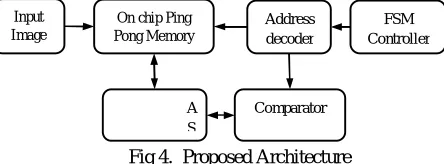
[image:3.612.232.402.149.254.2]neighbors (e.g. North and West), processes it and, in the next step, outputs results in the opposite direction (South andEast). Existing DWTarchitecture uses systolic array for fast wavelet processing. Here the input image to be processed is loaded into input buffer. Once image is received, address decoder is activated where its consists of two up counters: row counter and column counter. Row counter is always incremented when column counter completes the entire row. A comparator circuit is used compare coefficient with pixels read from memory. The difference between coefficient and block pixels are loaded second memory and process is repeated to perform 2D operation.
Fig 1. Sum of Absolute Difference (SAD) Calculation
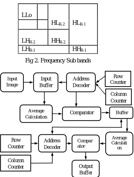
Systolic array do not lost their speed due to their connection unlike any other parellism. The processing element compute data and store independenly of each other . Systolic array is fast but difficult to implement .It has both the properties of pipelling and parellism. Pipelining and combinational logic design is to reduce power and chip size. Image memories and intermediate storage are major drawbacks associated with power consumption. In systolic array method based on concept of DWT for each subband division separate memory is needed. The DWT has four sub-bands (low-low, low-high, high-low, high-high).
LL : Horizontal Low Pass & Vertical Low Pass LH : Horizontal Low Pass & Vertical High Pass HL : Horizontal High Pass & Vertical Low Pass HH : Horizontal High Pass & vertical High Pass
[image:3.612.213.428.397.682.2]
Fig 2. Frequency Sub bands
Fig 3. Block Diagram of the Existing Method LLo
HLR-2 HLR-1
LHR-2 HHR-2
LHR-1 HHR-1
Input Image Input Buffer Address Decoder Average
Calculation Comparator
Row Counter Column Counter Row Counter Column Counter Address Decoder Compar ator Output Buffer Buffer Average Calculati on
PE
PE
PE
PE
PE
PE
©IJRASET 2015: All Rights are Reserved
864
III. PROPOSED METHOD
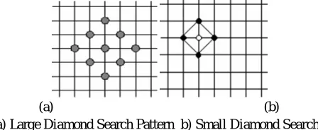
[image:4.612.203.425.269.351.2]DWT architectures utilize pipelining and combinational logic design to reduce power and chip size. However those designs don’t meet acceptable power. Image memories and intermediate storage are major drawbacks associated with power consumption. By replacing this issue with common memory architecture for both intermediate and default memory storage by using ASIP. An Application-Specific-Instruction-set Processor (ASIP) is a component used in system-on-a-chip design. The instruction set of an ASIP is tailored to benefit a specific application. This specialization of the core provides a tradeoff between the flexibility of a general purpose CPU and the performance of an ASIC. As we already know that existing DWT architectures uses more internal buffers to store intermediate pixel information. ASIP uses a controller known as Finite State machine controller that utilize common on chip memory that can be configured by ASIP. As shown in block diagram, image pixel is loaded into common on chip memory known as ping pong memory where ping refers inputting and pong refers outputting of pixels and coefficients. The term ping pong buffering is used for copying data between two processors direct memory access (DMA) transfers, for enhancing performance, to meet specific addressing requirements of a device. Row and column processors are used to read pixels from memory row wise and column wise to apply frequency band coefficients. The 1-D output is again stored in the same memory which is controlled by instruction sets of ASIC processor. The processors are activated once again to apply internal sub band coefficients
Fig 4. Proposed Architecture
The existing FELICS algorithm is designed only for spatial level compression. It uses current pixels and surrounding pixels for computing intensity level differences. This method should not compress if edges existing only at particular pixels. Also it doesn’t provide any compression technique for adjacent frames in video codec’s. For efficient compression, we propose a new method “Block Motion matching technique” where compression takes place at both Spatial and Temporal domain. In BMM, images are sub divided into micro blocks of 16x16 matrices and it is checked with nearby blocks. Also this method is applied for video compression techniques. The advantage of BMM over existing system is that it compresses block level compression instead of pixel level compression that improves execution speed and adapt for fast processing.
A. Project Description
The proposed DS block motion estimation employs two search patterns as illustrated in Fig., which are derived from the crosses (×) in Fig. 1. The first pattern, called large diamond search pattern (LDSP), comprises nine checking points from which eight points surround the center one to compose a diamond shape. The second pattern consisting of five checking points forms a smaller diamond shape, called Small Diamond Search Pattern (SDSP). In the searching procedure of the DS algorithm, LDSP is repeatedly used until the step in which the minimum block distortion (MBD) occurs at the center point. The search pattern is then switched from LDSP to SDSP as reaching to the final search stage. Among the five checking points in SDSP, the position yielding the MBD provides the motion vector of the best matching block.
B. Block Motion Matching
In video coding, block-based motion estimation plays a vital role for video compression. There are few block matching algorithms existing for motion estimation and motion compensation. In this paper a three step diamond search algorithm is proposed. The performance of this algorithm is compared with other algorithms by means of error metrics and number of search points. This algorithm achieves close performance with that of TSS. It uses less number of search points than TSS. When compared with original DS algorithm, this algorithm requires less computation time and gives an improved performance. Block-based motion estimation is one of the major components in video compression algorithms and standard. The objective of motion estimation is to reduce temporal redundancy between frames in a video sequence and thus achieve better compression. In block-based motion estimation, each frame is divided into a group of equally sized macro blocks and to find the best matching macro blockin the reference frame to the macro block being encoded in the current frame. Once the best match is located, only the difference between the two macro blocks and motion vector information are compressed.The most commonly used matching criterion is the sum of absolute differences (SAD), which is chosen for its simplicity and ease of hardware implementation. For
Input Image
Technology (IJRASET)
865
an M x N block, where Sl (x,y) is the pixel value of frame l at relative position x,y from the macro block origin and Vi = (dx, dy)
is the displacement vector, SAD can be computed as
There is a wide range of block matching algorithms (BMAs), full or exhaustive search is one in which the block matching process is performed for each possible macro block in the search window. Full search is computationally expensive but is very regular and easy for hardware implementation. Other block matching algorithms apply fast search techniques such as three-step search (TSS), hierarchical BMA, diamond search, hexagon search, and simplex search (SS) algorithm. Recently, the FTS algorithm was introduced and it was shown that its performance compares very well with other fast BMAs. In these fast algorithms, only selected subsets of search positions are evaluated using SAD. As a result, these algorithms usually produce sub-optimal solutions but the computational saving over FS is significant. When it comes to hardware implementation on the other hand, the number of SAD calculations is not the only criterion for the choice of a motion estimation algorithm. Other criteria, such as algorithm regularity, suitability for pipelining and parallelism, computational complexity and number of gates which directly affect power consumption and cost of hardware, are also very important
C. Motion Estimation
Video coding is an important process in many multimedia applications. In addition to spatial redundancy, temporal redundancy
plays a vital role in the transmission of video frames. Motion estimation is a technique used to reduce the temporal redundancy. It uses the correlation between the successive frames to predict the content of frames. In the motion estimation process the frame is divided into number of non overlapping areas known as blocks. Each block can be with a standard size of 16×16. The difference between the current frame and the predicted frame contents is calculated in motion estimation. In addition to motion estimation, some additional information’s are also needed to indicate any changes in the prediction process. This is known as ‘Motion Compensation’. Motion estimation and motion compensation algorithms are used to obtain strong temporal redundancy. Full search block matching algorithm is an algorithm which provides a better performance with more number of search points. But, there is a tradeoff between the efficiency of an algorithm and the quality of the prediction image. The suboptimal algorithms are used for this purpose. These algorithms are computationally more efficient but they do not give a good quality as in FSBMA. The suboptimal algorithms used in video transmission are Three step search (TSS), New three step search (NTSS), Diamond search (DS) and the like.
The search speed and the performance of an algorithm are determined by the shape and size of the search patterns. The TSS and NTSS algorithms are using a squared shape pattern, whereas the diamond search algorithm uses a Diamond shape. This DS algorithm uses an unrestricted center-biased searching concept and so it is computationally inefficient. A three step diamond search algorithm is proposed to attain a computationally efficient search with a reasonable distortion performance.
D. Diamond Search Algorithm
The shape of the search pattern has an impact on the performance of the Algorithm. Fast block matching algorithms such as TSS, NTSS are having a square shape search pattern and provide reasonable performance. The distribution of global minimum points is centered at the center of the search window. A center biased NTSS is used to achieve better performance than TSS. But it losses the regularity and simplicity. The diamond search algorithm provides a better performance than the TSS, NTSS algorithms. The DS algorithm uses a diamond shape pattern with nine search points, four points located at the corners and another four points located at the midpoint of the edges of the diamond shape. This algorithm uses an unrestricted center biased searching process .The diamond search employs a large diamond search pattern (LDSP) [Fig 5.1(a)] and a small diamond search pattern (SDSP) [Fig 5.1(b)].
(a) (b)
Fig 5. a) Large Diamond Search Pattern b) Small Diamond Search Pattern
[image:5.612.194.418.600.692.2]866
[image:6.612.215.397.124.298.2] [image:6.612.236.378.454.539.2]uses five search points in the new LDSP if the MBD point is the corner point [Fig 3.(a)] and three search points if the MBD point is at the edge of the pattern [Fig 3.(b)]. The LDSP pattern is used until the center point becomes the Minimum Block Distortion (MBD) point. Once the MBD point is at the center, the search is switched to SDSP which uses four checking points [Fig 3.(C)].
(a) (b)
(c)
Fig 6. a) MBD point is at corner. b) MBD point is at edge c) MBD point is at center
The MBD points thus obtained will give the motion vector. The DS algorithm reduces the susceptibility of getting stuck at local minima due to its compact shape and relatively large step size in the horizontal and vertical direction. Thus the DS algorithm gives a faster processing and similar distortion performance with the other fast searching algorithms. The increase in number of steps leads to more number of search points which has an effect on the speed of the algorithm. This makes the algorithm computationally inefficient. A three step diamond search (TSDS) is proposed to overcome this disadvantage.
E. Three Step Diamond Search Algorithm
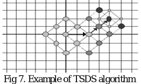
The proposed TSDS algorithm uses the same type of patterns used in DS algorithm with a reduction in step size. Based on the location of the MBD point, the number of checking points to be used in the successive steps varies. The number of searching steps is reduced to three and the SDSP search is reached at the third step regardless of the location of the MBD point.
Fig 7. Example of TSDS algorithm
The LDSP pattern is repeatedly used until the center point becomes the MBD point. Thus the compact configuration and reduced number of search points provide an improved performance than the other existing algorithms. An example of this algorithm is given in Fig 5.3. The algorithm for this TSDS algorithm is summarized as follows.
Algorithm
Step1: Initial LDSP is centered at the origin of the search window. Now, test each points in the search pattern .If the MBD point is the center point go to step3. Otherwise go to step2.
Step2: Form a new LDSP with the MBD point as the center point. If the new MBD point is at the center position, go to step3.Otherwise repeat this step for one more time.
Step3: Form the SDSP pattern with the previous MBD point as the center point. The new MBD point obtained in this step becomes the final solution i.e., the motion vector (x, y). The number of search points depends on the location of MBD point. The MBD point also determines the search direction.
IV. SIMULATION RESULTS
A. PERFORMANCE COMPARISON
Technology (IJRASET)
867
the search window. The performance of the algorithm is evaluated by error metrics such as the Mean Square Error and signal to noise ratio. The performance analysis has been done for an “officer” sequence
(a)
[image:7.612.219.385.104.347.2](b)
Fig 8. Performance comparison a) Mean square error b) Peak Signal to noise ratio
Simulation results show that, it gives a better performance compared with the existing TSS and DS algorithms with a reduction in step size also. The search is confined within the search window and the reduction in number of steps results in reduction in computational complexity. The criterion used for the distortion measurement is Sum of Absolute Difference (SAD), which gives the MBD point for the motion vector calculation. The pixels are arranged in such a way that two in horizontal direction and in vertical direction, and one in each diagonal direction. This makes the algorithm to reach a global minimum point. The maximum number of search points used is 23 whereas the TSS uses 25 search points. It achieves a close MSE performance with the DS, TSS, NTSS algorithms for the image sequences with small motion as well as large motion contents.
B. Output Parameters
We use two memory unit, one for current frame and another one for reference frame. For diamond search algorithm, we need 9 pixel values from both current and reference memory. The ratio of compression is based on this 9 pixel values. Thus output is based on 9 pixel values of frames, Sum of Absolute Difference and memory addressing parameters.
1) Memory Read/Write Process: Above simulation results shows initial data
loading from memories and address decoding logic. Initially Reset signal holds ‘1’ and after 100ns it downs to low with enable signal high. Here we use address decoding logic that control pipelining. After completing a macro blocks from 1st row of the frame, it needs to be continued to same row until it finishes 1 to 640 pixels address. After completing first row, address decoder changes its row address from 0-15 to 16-31 pixels block. This process will be continued until block matching algorithm completes whole frame.
[image:7.612.113.504.614.715.2]868
2) Motion Detection
We know that compression will be efficient if the micro motions of the images are identified. Since cross diamond search algorithm is efficient method to identify such micro motions. If concurrent frames have same information, then compression ratio would be high and block matching will be completed within few cycles. Above fig. shows there is minimum number of pixel changes between current frame and reference frame so that only 3 compression vectors are executed.
[image:8.612.107.503.148.276.2]
Fig 10. Motion detection
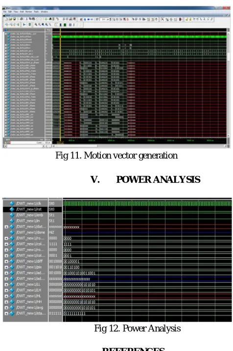
3) Motion Vector Generation
Figure shows complete execution to identify compression vectors. There are 9 pixels are read from current memory block and 9 from reference memory block. It SAD value is executed using comparator. Based on SAD point value, FSM controller moves centre point pixel axis to minimum SAD point. This process is executed for the complete frame and motion vectors are loaded into vector memory.
Fig 11. Motion vector generation
V. POWER ANALYSIS
Fig 12. Power Analysis
REFERENCES
[image:8.612.187.425.337.695.2]Technology (IJRASET)
©IJRASET 2015: All Rights are Reserved
869
[2] Tsung-Han Tsai, Yu-Hsuan Lee, and Yu-Yu Lee, “Design and Analysis of High-Throughput Lossless Image Compression Engine Using VLSI-Oriented FELICS Algorithm,” IEEE Trans. Very Large Scale Integr. (VLSI) Syst., Vol. 18, No. 1, January 2 010.
[3] R.Li.B.Zeng, and M.L.Liou, “A New three-step search algorithm for block motion estimation”, IEEE Transactions on circuits and systems on video technology, vol.6.pp.438-44 2 , August 1994.
[4] W. Sweldens, “The lifting scheme: A custom-design construction of biorthogonal wavelets,” Appl. Comput. Harmon. Anal., vol. 3, no. 2, pp. 186–200, Apr. 1996.
[5] P.-C. Wu and L.-G. Chen, “An efficient architecture for two- Dimensional discrete wavelet transform,” IEEE Trans. Circuits Syst. Video Technol., vol. 11, no. 4, pp. 536–545, Apr. 2001.
[6] C.-T. Huang, P.-C. Tseng, and L.-G. Chen, “Analysis and VLSI Architecture for 1-D and 2-D discrete wavelet transform,” IEEE Trans. Signal Process.,vol. 53, no. 4, pp. 1575–1586, Apr. 2005.
[7] C.-Y. Xiong, J.-W. Tian, and J. Liu, “Efficient architecture for Twodimensional discrete wavelet transform using lifting scheme,” IEEE Trans.Image Process., vol. 16, no. 3, pp. 607–614, Mar. 2007.
[8] C.-C. Cheng, C.-T. Huang, C.-Y. Cheng, C.-J. Lian, and L.-G. Chen, “Onchip memory optimization scheme for VLSI implementation of line-based two dimensional discrete wavelet transform,” IEEE Trans. Circuit Syst. Video Technol., vol. 17, no. 7, pp. 814–822, Jul. 2007.