©IJRASET 2015: All Rights are Reserved
9
Automatic Irrigation System using Embedded
System and GSM Technology
A.Ramakrishna1, Ch. Kanchana2, B.sashanksrikar3, D.Barathreddy4, D.Sravankumar5
Dept. of ECE, VITS College of Engineering, Visakhapatnam, Andhra Pradesh, India
Abstract- The increase in human population resulted in the increase of the demand for food production. Farmers are unable to meet the requirements due to irregular water supply. To meet the demand, a new type of system is needed to regulate the irrigation. Automatic irrigation is a form of irrigation system that incorporates the theory of digital control and feedback system with irrigation. In this system of irrigation, critical information (soil moisture content, humidity, sunlight) is sent to a microcontroller which is provided by sensors which is used by the microcontroller to schedule irrigation by turning on or off a water pump that supplies water to the farmland.
Keywords- Microcontroller, sensors, moisture, irrigation, sprinkler.
I. INTRODUCTION
Agriculture is constantly losing land because of various reasons. India has arable land area of 159.7 million hectares out of which 82.6 million hectares is good for farming. But only 8% of the Indian population is working hard to cultivated these lands. Farming is of utmost importance to the survival of the inhabitants of an area. Considering the rate of population growth, there arises the needs to intensify the rate of food crop production so as to compensate for the increasing food demand. A method to reduce the problems associated with farming and as well increase food crop production is the implementation of a controlled technique to meet the soil moisture requirement for different food crops grown in respective locations. Automatic irrigation is a form of irrigation system designed to control the irrigation in accordance with the crop requirements. In this system information of various parameters such as soil moisture content, humidity, etc., are sent to a microcontroller by sensors. The microcontroller uses this information to regulate irrigation by turning on or off a water supply.
II. IRRIGATION SYSTEM
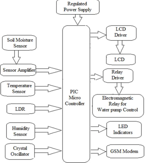
Figure 1: Layout of Automatic irrigation system
A. Hardware Description
Automatic Irrigation System using PIC Microcontroller can be used for various types of crops. The current irrigation unit is designed for only a single crop. When the system is powered ON, four different parameters are displayed on the LCD display. They are light, temperature, humidity and soil moisture. The parameters are displayed continuously with the variations occurring from time to time.
1) Microcontroller: The design uses PIC16F877A microcontroller. PIC16F877A is a family of modified Harvard Architecture microcontroller made by Microchip Technology. This is powerful microcontroller with nanosecond instruction execution and easily programmable with only 35 single word instructions. The entire automation of the system is done by this microcontroller. It has an inbuilt Analog to Digital converter. Because of this we do not require any ADC to be connected externally.
Figure 2: 40 Pin PIC16F877A Microcontrollers
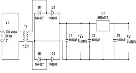
2) Power Supply
[image:3.612.195.410.515.664.2]-15V, 0V, 15V and 0.5 ampere. Transformer selection is based on the fact that regulator ICs require around 14v as input considering dropout voltage (around 2v), in order to obtain 12v power supply. The transformer steps down ac voltage from 230v ac to 15v AC. It is then given to bridge rectifier. Bridge rectifier converts the AC voltage into pulsating DC. It is then given to regulator IC which gives a constant dc voltage. These voltages are given to other ICs as VCC or reference.
b) Bridge Rectifier: Rectifier converts ac voltage into dc voltage. In the rectifier four diodes are connected in the form bridge along with a capacitive filter to generate the DC signal. Its input is from transformer and output is given to the voltage regulator IC.
[image:4.612.196.419.219.339.2]c) Voltage regulator: The Voltage regulator IC gives constant DC voltage at output in spite of fluctuations in input. The design uses IC 7805 as the voltage regulator. It gives an output of 5V DC.
Figure 3: Power Supply
3) Soil Moisture Sensor
The commonly used soil moisture sensors are the electrodes or steel probes. In the design we are using the normal wires as electrodes. The soil moisture sensor follows the basic principle of a megger. The principle is that the moisture content in the soil is inversely proportional to the earth resistance. So the decrease in soil moisture results in the increase in earth resistance. This information is used by the microcontroller to drive the relay connected to the irrigation motor.
4) Light Dependent Resistor (LDR)
The design uses NSL19-M51 Light dependent resistor. In the night the resistance is very high and up to 1MΩ but in the day time the resistance drops to a few ohms depending on the light intensity. So depending on the output resistance, the light intensity or the time of the day is determined. This helps us in generating the conditions
5) Temperature Sensor
The design uses LM35 temperature sensor. It is a precision integrated-circuit with an output voltage linearly-proportional to the Centigrade temperature. It can determine the temperatures over a range of −55°C to 150°C.It does not require any external calibration or trimming to provide typical accuracies. Here the temperature sensor is used to determine the fire accidents in crops. If there is a fire accident, the microcontroller drives the relay connected to the sprinkler system to put off the fire. For the sake of safety a message is sent to the farmer with the help of GSM Modem. The output voltage of temperature sensor rises at a rate of 10mV/°C. The output voltage ranges between 6V and -1V.
6) Humidity Sensor
The design uses HMTC1A2 Humidity sensor module. It comprises of HSS1101 Humidity sensor and LM35 Temperature sensor. It has the characteristics of stable, high accuracy, quick response and good crossing-over. In the design humidity sensor is used to check the humidity in the air around the crops. The increase in humidity is because of evaporation of water from the leaves which results in withering of the leaves. So the increase in humidity is checked and the sprinklers are activated to attain the moisture on the crops. The reason for the usage of temperature sensor separately is because this model cannot determine the temperatures beyond 50°C.
7) Light Emitting Diode (LED)
The relay unit is designed in such a way that when a control signal is obtained from the microcontroller, the acts as a switch that turns ON/OFF the pump connected in the output. The relay unit consists of a BC547 transistor, 5 pin 12V relay and 1N4007 p-n junction diode. The transistor is connector in Common emitter configuration where the collector is connected to the 12V supply and the emitter is grounded. When the supply is given to the base of the transistor, it turns ON the relay and when the supply is cut
[image:5.612.196.413.154.273.2]off, the relay is cut off. The diode is added in the circuit to provide the protection of the circuit from back EMFs.
Figure 4: Interfacing pump with relay unit
9) Liquid Crystal Display (LCD)
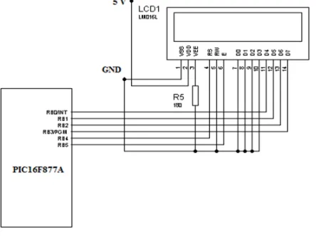
Figure 5: Interfacing LCD with PIC microcontroller
The LCD will display the alphabets, numbers, characters and symbols. The LCD used here is eight bit parallel type and the display size is 16x2. Liquid Crystal Display is used for displaying the sunlight, humidity, temperature and soil moisture values. LCD consists of three control pins and eight data pins. Based on the commands given to the control pins, data i.e the parameter values are written simultaneously to the LCD. The four data pins D4 to D7 of the LCD are connected to the PORTB pins RB0 to RB3 while the remaining data pins are grounded. Two control pins RS and E are connected to PORTB pins while the RW is grounded. RB4 and RB5 are used for register select (RS) and enable (E) respectively. Initially the display is shows four parameters names along with their values. The parameter values to be displayed are sent to the LCD simultaneously. LCD accepts only the ASCII values as input. Hence the hexadecimal values are converted into ASCII values and it is fed to the LCD to display the temperature.VCC and VSS are provided with 5V and ground respectively. VEE used for controlling LCD contrast was grounded so as to have a standard contrast.
[image:5.612.197.419.339.505.2]Figure 6: Interfacing Sensors with PIC microcontroller
B. Software Desciption
1) MiroC PRO: MikroC PRO for PIC is an integrated development environment designed especially for the PIC microcontrollers. It provides the easiest way of developing applications for embedded systems, without compromising performance or control. It features a highly advanced IDE, ANSI compliant compiler, broad set of hardware libraries, comprehensive documentation, and plenty of ready-to-run examples. It organizes applications into projects consisting of a single project file (file with the .mcppi extension) and one or more source files (files with the .c extension). This compiler allows the management of several projects at a time. But the source files can be compiled only if they are part of the project. A project file design in this IDE contains project name and optional description, target device in use, device clock, list of the project source files, binary files (*.mcl) and other files.
2) Proteus: PROTEUS is a simulator tool that allows engineers to run interactive simulations of real designs for circuit simulation. It has a range of simulator models for popular micro-controllers and a set of animated models for related peripheral devices such as LED and LCD displays, keypads, etc. It is possible to simulate complete micro-controller systems and thus to develop the software for them without access to a physical prototype. The design of the project has been simulated in this tool. It used various simulator models such as PIC16F877A microcontroller, Humidity Sensor, Temperature sensor, Light Dependent Resistor (LDR),16X2 Liquid Crystal Display (LCD), Light Emitting Diode (LED), Relays, Resistors, Capacitors, diodes, transistors, Voltage regulators, MAX232 IC, Quartz Crystal and sources. By using the mentioned simulator models the result has been verified with the hardware results.
III. RESULT
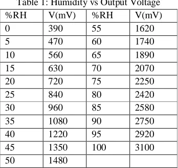
Table 1: Humidity vs Output Voltage %RH V(mV) %RH V(mV)
0 390 55 1620
5 470 60 1740
10 560 65 1890
15 630 70 2070
20 720 75 2250
25 840 80 2420
30 960 85 2580
35 1080 90 2750
40 1220 95 2920
45 1350 100 3100
50 1480
A. Advantages
1) This irrigation system uses less water than conventional watering methods, such as sprinklers.
2) Smaller amounts of water applied over a longer amount of time provide ideal growing conditions.
[image:6.612.219.393.534.698.2]©IJRASET 2015: All Rights are Reserved
14
5) Water is delivered only to the section of the field where it's needed but not to the whole field.
6) This system is adaptable and can be modified easily to adjust to the changing needs of the water supply to the crop.
IV. CONCLUSION
The system provides with several benefits and can operate with less manpower. The system supplies water only when the moisture in the soil goes below the reference. Due to the direct transfer of water to the roots water conservation takes place and also helps to maintain the moisture to soil ratio at the root zone constant to some extent. Thus the system is efficient and compatible to the changing environment. Also the system saves the water and improves the growth of plants. The other advantage is that the very irrigation levels are regulated with the help of various sensors. The Light Dependent Resistor is used to check the presence of sunlight to change the irrigation levels from time to time. The Temperature sensor is used to check the occurrence of the fire accidents and control them with the help of sprinkler system. An added advantage is that the humidity in the air at the crop level is checked and any increment of the value above the reference level will immediately activate the sprinkler system. It is because the increase in humidity is due to the evaporation of water from the leaves. So when we can retain the soil moisture just by activating the sprinkler system and moisturising the crops.
V. FUTURE SCOPE
Water resources can be utilized efficiently based on various parameters in order to make the agricultural sector more productive to reach the requirements of the demand. In automatic irrigation system the optimum level of the parameters varies in different seasons and at different times. Water is allowed to the field of crops depending upon the particular season. So the irrigation occurs more in summer season, less in rainy season and moderate in winter season. Other parameters such as plant growth at different stages and weather condition can also be taken into consideration to determine the water requirement for the crop. This will improve agriculture leading to economical development of our nation. The irrigation system can also be interfaced with solar energy production module. This can eradicate the problem of lack of electricity in remote areas. In this way the irrigation system can be upgraded to a new level to eradicate the problems of food productivity and to meet the demand.
VI. BIBLIOGRAPHY https://en.wikipedia.org/ http://www.slideshare.net/ http://www.mikroe.com/mikroc/pic/ http://www.academia.edu http://www.ijoart.org REFERENCES
[1] Advanced Micro processors and Peripherals by A K Ray and K M Bhurchandi, Tata McGraw Hill Private Limited. [2] Micro controllers, Theory and Applications by Ajay V Deshmukh, Tata McGraw Hill Private Limited.
[3] Soil Moisture and Temperature sensor based intelligent irrigation water pump controlling system using Microcontroller by Swati Devabhaktuni- International Journal of Emerging Trends in Engineering and Development (IJLTET).
[4] Automatic Drip Irrigation System using PIC Microcontroller by Lincy Luciana- International Journal of Emerging Trends in Engineering and Development (IJLTET).