5
X
October 2017
FEA Analysis of Four Strokes Spark Ignition Split
Cycle Engine
Ch. Mani Kumar1, Sk. Salman Basha2, Y. Raghu Ram3, R. Narendra Kumar4 1, 2, 3, 4
Asst. Professor, Department of Mechanical Engineering, Sasi Institute of Technology & Engineering. Tadepalligudem, India.
Abstract: Engine is a very important component in automobiles and it is act as a prime mover. Engine is a device which will converts heat energy into mechanical energy. Engine transmits power to road wheels against to sprung and unsprug weights which results the engine components are stressed. The engine components like cylinder, piston and piston rings are exposed to heat so that the thermal stresses are induced. The connecting rod and crankshaft are exposed to static and dynamic loads which results these components are stressed. Based on the above said points the stress and strain analysis is very important for engine components. The main aim of this work is to design and simulate the thermal and structural stress analysis of a split cycle four stroke spark ignition engine. The engine was designed by using solid works software and the three-dimensional thermal and structural analysis was done in the ANSYS software. The dynamic analysis of crank shaft was done by ANSYS.This work investigated the amount of heat flow in the engine components (compression and expansion cylinders and pistons) and failure analysis of engine components (Connecting rod and Crank shaft) of a split cycle four stroke spark ignition engine.
Key-Words: - SOLIDWORKS, FEA, Split Cycle engine.
I. INTRODUCTION
Internal combustion engine is a device which will converts heat energy in to mechanical energy. Split cycle engine is advanced engine as compared to conventionalICengine. In conventional engine (Four stroke S.I. engine) all process like suction, compression, expansion and exhaust occurs in single cylinder but in split cycle engine two process (Suction and Compression) occurs in compression cylinder and remaining two process (Expansion and Exhaust) occurs in expansion cylinder.
Fig.1. Working of conventional four stroke S.I. Engine
II. LITERATURE REVIEW
SudeerGowdPatil et.al. (2012)The CFD analysis is carried out for both the conventional spark ignited engine and the Scuderi split cycle engine. The peak pressure, thermal efficiency and power output obtained in the Scuderi engine is 11 bar at 300 rpm, 5% and 20% more than the conventional engines [1].Prince Bora et.al.(2015)The split engines are more efficient than the conventional IC engines. The area under the P-V curves is also greater than that of the conventional IC engines [2].Guangyu Dong et.al.(2015)Studied that expansion ratio is increased to 26 since a 2.8% total efficiency improvement still can achieved from over expansion He was concluded that through the system optimization, a total thermal efficiency can be increased on split cycle engine[3].AnshulJangalwa et.al.(2013)Concluded that the Scuderi split cycle engines are more efficient than conventional engine and therefore they are future alternatives of the conventional engines. It reduces the emission of engine[4].Ulrik Larsen et.al (2014)In the Split-cycle, the working fluid concentration can be changed during the evaporation process in order to improve the match between the heat source and working fluid temperatures simplified cost analysis suggests higher purchase costs as result of increased process complexity [5].
III. METHODOLOGY
Fig.3. Drafting and analysis chart of four stroke split cycle S.I. engine
A. 3D models of split cycle engine components
The geometric models of split cycle engine coponents was designed in the solidworks
Fig.5. Proposed model of connecting rod
Fig.6. Proposed model of crank shaft
Fig.7. Assembly of four stroke spark ignition split cycle engin
B. Fem Analysis
The strength, safety, emission control and heat transfer are very important issues in engines. To meet these requirements, need to perform static structural and thermal analysis on split cycle engine. Static structural and thermal analysis was done by using ANSYS software and engine components are designed in solidworks.
C. Material Selection
Structural Steel
1 Yield Strength 250 MPa
2 Ultimate Strength 460MPa
3 Density 7.85e-006 kg mm^-3
4 Coefficient of Thermal
Expansion
1.2e-005 C^-1
5 Specific Heat 4.34e+005 mJ kg^-1 C^-1
6 Thermal Conductivity 6.05e-002 W mm^-1 C^-1
7 Resistivity 1.7e-004 ohm mm
8 Strength Coefficient 920MPa
D. Meshing
Fig.8. The proposed meshing model of split cycle engine components (Cylinder and Piston and connecting rod assembly)
E. Boundary conditions
F. . Loading
Fig.10. Load is acting on piston and connecting rod assembly
[image:8.612.198.416.112.255.2]IV. RESULTS AND DISCUSSIONS
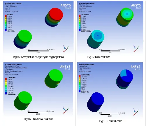
[image:8.612.62.551.370.720.2]Fig 13 shows the maximum von miss stress of stainless steel connecting rod. The maximum von miss stress value was 103.42 MPa.Fig.17.& 21 shows the total heat flux of stainless steel compressions and expansion pistons and cylinders. The total heat flux values were 3.57 and 21.14 w/mm2. Fig.24. shows the maximum von miss stress of stainless steel crankshaft under dynamic conditions. Thevalue of Von miss stress were 0.22MPa.
Table.2. Static structural analysis of split cycle engine connecting rod and piston assembly
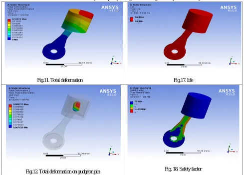
Fig.11. Total deformation Fig.17. life
Fig.13. Total deformation on connecting rod big end Fig.19. Biaxiality indication
Fig.14. Total deformation on connecting rod Fig.20. Equivalent alternating stress
Fig.12. Equivalent elastic strain on connecting rod Fig.14. Strain energy
Table .3.Thermal analysis of compression and expansion pistons
Fig.15. Temperature on split cycle engine pistons Fig.17.Total heat flux
Fig.16. Directional heat flux
Table.4. Steady State Thermal analysis of compression and expansion cylinders
Fig.19. Temperature distribution of compression and expansion cylinders
Fig.21.Total heat flux of compression and expansion cylinders
Fig.20..Directional heat flux of compression and expansion cylinders
Fig.22. Thermal error of compression and expansion cylinders
Table.6. Dynamic analysis of crankshaft
Fig.24. Equivalent stress of crankshaft Fig.27.Strain energy of crank shaft
Fig.25..Maximum principal stress of crankshaft
V. CONCLUSION
Modeling and FEA analysis of split cycle S.I. engine components was done by using SOLIDWORKS and ANSYS 15 software. Static structural analysis was carried out on piston and connecting rod assembly considered 1 MPa load. At 1 MPa load, the total deformation of each component, Von miss stress of connecting rod, strain energy and life values were noted. The study state thermal analysis was carried out on both compression and expansion pistons& cylinders at 700otemperature. The total heat flux values of both piston and cylinder values were noted. In this analysis observed structural steel material is best for all components. All the result values were within the acceptable limits.
REFERENCES
[1] Study on Performance Characteristics of Scuderi – Split Cycle Engine,sudeerGowd Patil1,Martin A.J.2,Ananthesha3, Scuderi Group LLC (2012). [2] The ScuderiRevolution:A Review Prince Bora1,Neeraj Joshi2,PriyankaHire3,Vol.No.3.SpecialIssue No.1,August 2015
[3] A novel split cycle internal combustion engine with integral waste heat recovery, Guangyu Dong, Robert Morgan, Morgan Heikal.
[4] Scuderi Split Cycle Engine: A Review Anshul Jangalwa1, AdityaKumarSingh1,AkshayJain1andAnkit Barua1 *Corresponding Author: AnshulJangalwa, ISSN 2278 – 0149, Vol. 2, No. 4, October 2013