http://dx.doi.org/10.4236/jpee.2014.24091
Research on Evaluating Index of Lightning
Protection Safety Performance of High
Voltage Overhead Transmission Line
Yi Luo
1, Jingzhou Jiang
1, Yu Nong
1, Shizuo Li
21Baise Power Supply Bureau Guangxi Power Grid Corporation, Nanning, China 2Institute of Electrical Engineering Guangxi University, Nanning, China Email: [email protected], [email protected]
Received February 2014
Abstract
In order to improve the lightning protection performance of transmission lines, lightning protec-tion management has been divided into every tower that lightning protecprotec-tion performance has been evaluated respectively. According to factors such as landform, span, tower type, grounding resistance, isolator type, and so on, relative ratio of tripping operation of every tower in the line has been calculated to evaluate its lightning protection safety performance, it is beneficial to op-eration maintenance and lightning reconstruction of transmission lines.
Keywords
Transmission Lines; Lightning Protection Safety Performance; Evaluating Index; Ratio of Lightning Tripping Operation
1. Introduction
The ratio of lightning tripping operation of high voltage overhead transmission line is very high at all time, it always exceeds 70% of total tripping operation, and lightning tripping operation becomes the main factor that may endanger the safety of power system [1] [2].
Usually, there are few indexes to evaluate the lightning protection performance of high voltage overhead transmission line, such as lightning withstand level and ratio of tripping operation, those indexes are rude and unitary, and cannot reflect the influence of height, landform, span, tower type, grounding resistance, isolator type, and so on, of every tower.
In order to improve the lightning protection performance of transmission lines, lightning protection manage-ment has been divided into every tower that lightning protection performance has been evaluated respectively according to different parameters of every tower [3].
Every tower of a transmission line has different parameters such as height above sea level, tower height, on-ward and backon-ward spans of conjoint towers, distance of two overhead ground wires, so lightning ratio of every tower is different when there is thundercloud above transmission line. To reflect those differences, relative lightning ratio k is introduced.
(
)
MAX ( Max Max) Max
W H D
S k
S W H D
+
= =
+ (1)
Here H is the height above sea level of overhead ground wires, W is the distance between two overhead ground wires, D is half of sum of onward and backward spans, HMAX, WMAX, DMAX are maximums of those pa-rameters of all towers in a transmission line. Obviously S is the area of an enlarged rectangle which length is half of sum of onward and backward spans, and which width has been extended on account of the effect of height above sea level of overhead ground wires. SMAX is the biggest area of those parameters of all towers. k equals to ratio of the equivalent area of one tower to the biggest area.
B. Probability of Sustained Arc Probability of sustained arc ν is:
0.75 2 [4.5 14] 3 U l
ν = − −
(2) Here U is the line voltage and l is the length of the isolator.
C. Withstand Level of Lightning Direct Stroke to Tower Withstand level when lightning is striking to tower directly is:
50% 2
d (1 )
2.6 2.6 U I h L R q β = + + − (3)
Here U50% is 50% impulse spark over voltage of isolator, β is the shunt coefficient of overhead ground wires, R is the grounding resistance of tower, L is the inductance of tower, hd is the height of conductor to ground, q is the coupling coefficient between conductor and overhead ground wire.
D.Withstand Level of Lightning Shielding Failure
Withstand level when lightning is striking to conductors directly is:
50% 2
100 U
I = (4)
E. Direct Stroke Rate and Shielding Failure Rate
There is a relationship between striking distance rS and lightning current magnitude I:
0.75 7.1
S
r = I (5)
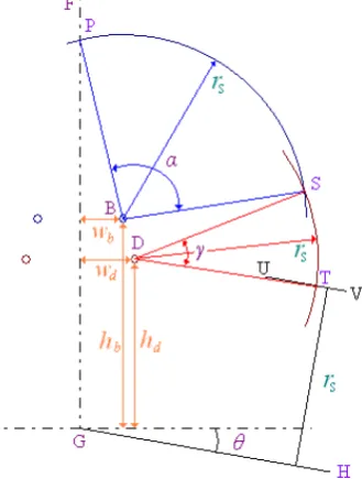
Geometrical model of direct stroke and shielding failure is illustrated in Figure 1, θ is the incline angle of ground shown as line GH, GF is the centric line of a tower, B and D are overhead ground wire and conductor respectively of one side.
Draw an arc PS which center is in the point B and radius is rS, and another arc ST which center is in the point
D and radius is rS, and a line UV which is paralleled to ground with a distance of rS.
Obviously, if imminent lightning leader gets to arc PS, lightning may hit to the overhead ground wire, on the other hand, lightning may hit to the conductor when imminent lightning leader comes to arc ST. Direct stroke rate and shielding failure rate can be calculated by angles α and γ corresponding to arc PS and ST.
Direct stroke rate η(rS) is:
( )
rSα η
α γ
=
+ (6)
Shielding failure rate ξ(rS) is:
( )
rSγ ξ
α γ
=
Figure 1. Direct stroke and shielding failure.
Angles α and γ have a relationship with tower parameters and striking distance rS, according to the
geometric-al model in Figure 1, they can be given as:
2 2 2 2
2
2 2
1 1
( ) ( ) ( )
( ) 4( )
4 ( ) ( )
sin sin ( )
2 2
d b b d S d b
d b b d
d b b d
b
S S
w w h h r w w
h h h h
w w h h
w
r r
π
α − −
− + − −
− + − − −
− + −
= + −
(8)
(
)
(
) (
)
(
)
(
) (
)
( )
(
( )
)
( )
2 2 2 2
2 2 2 1 2 2 1 2 4 4
sin ( )
2
sin sin(θ) 1 sin ( sin )
sin ( )
(1 sin ( ))
d b b d S d b
b d b d
d b b d
S
S d d S S d d
S
w w h h r w w
h h h h
w w h h
r
r h w r r h w
r
γ
θ θ θ
θ − − − + − − − + − − − − + − = − − − + − − − − + (9)
If γ < 0, then let η = 1 and ξ = 0, this indicates that shielding failure will not occur under that lightning current magnitude Iand its striking distance rS.
Middle phase will be neglected. Direct stroke rate and shielding failure rate of another side of tower can be computed by Formulas (6)-(9) in the same way, and will be added up.
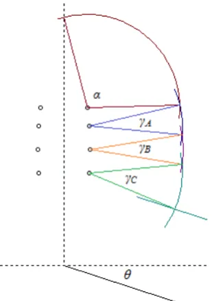
For double lines on the same tower, angles α, γA, γB, γC, as illustrated in Figure 2, must be calculated, then,
( )
SA B C
r α
η
α γ γ γ
=
+ + + (10)
( )
A B CS
A B C
r γ γ γ
ξ
α γ γ γ
+ +
=
+ + + (11)
F. Ratio of Direct Stroke Tripping Operation
Probability that lightning current magnitude exceeds I is:
( )
10 108I
Figure 2. Double lines on the same tower.
( )
0.02132 10108I
f I = × − (13) Ratio of direct stroke tripping operation is:
( ) ( )
1
1 I S
k =ν
∫
∞f I η r dI (14)G.Ratio of Shielding Failure Tripping Operation Ratio of shielding failure tripping operation is:
( ) ( )
2
2 I S
k =ν
∫
∞ f I ξ r dI (15)H.General Evaluating Index
After considering the effect of tower type, height over sea level, span, ground resistance, isolator, landform, general evaluating index of lightning protection safety performance of every tower is:
1 2
( )
J=k k +k (16)
By all appearances, the smaller general evaluating index of a tower is, the better lightning protection safety performance of that tower is, on the other hand, the bigger general evaluating index of a tower is, the worse lightning protection safety performance of that tower is.
Supposed that JMAX is the maximum of evaluating indexes of all towers in a transmission line, relative eva-luating index can be defined as:
Max
100 r
J J
J
= × (17)
Relative evaluating index expressed by percentage is very intuitionistic, and it is easy to give a taxis to all towers in a transmission line according to relative evaluating index.
3. Evaluating Software
Based on MS Visual Basic 6.0, evaluating software of lightning protection safety for high voltage overhead transmission lines is developed, it includes six component: lines edit, tower edit, isolator edit, evaluating analy-sis, graph show, and version information.
com-ponent manages tower type and its main parameter. Isolator edit comcom-ponent manages isolator type, save 50% impulse spark overvoltage and length of every isolator (Figure 3).
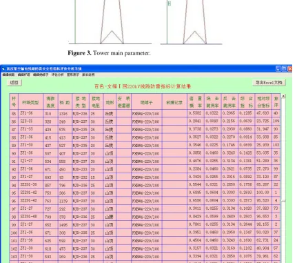
Figure 4 shows the interface of the evaluating result. Result includes relative lightning ratio, ratio of direct stroketripping operation, ratio of shielding failure tripping operation, general evaluating index, relative evaluat-ing index and taxis. All parameters of a transmission line and evaluatevaluat-ing result can be exported to an Excel document.
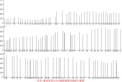
[image:5.595.199.420.183.379.2]Figure 5 shows height and span of atransmission line.
[image:5.595.101.533.309.690.2]Figure 3. Tower main parameter.
Figure 5. Height and span of a transmission line.
4. Conclusions
By introduction of relative lightning ratio, the effect of tower parameters, such as height above sea level, tower height, onward and backward spans of conjoint towers, distance of two overhead ground wires can be numerated, and that is easy to reflect the difference of every tower.
Tower type and incline angle of ground have a distinct influence to direct stroke rate and shielding failure rate, and are main parameters of the difference.
Relative evaluating index of of every tower is very intuitionistic and is beneficial to operation maintenance and lightning reconstruction of transmission lines.
References
[1] Zhu, S.Y., Deng, Y.R. and Li, M.G. (2010) Analysis and Countermeasure of Lightening Disturbance of Transmission Line in Guangxi Power Grid. Guangxi Electric Power, 33, 1-5.
[2] Gu, S.Q., Chen, J.H., Chen, W.J., Li, X.L., Tong, X.F. and Zhang, R. (2009) Evaluation Method of the Time-Space- Difference of Lightning Protection Performance of Transmission Lines. High Voltage Engineering, 35, 294-298. [3] Zhou, H.M. and Peng, X.Y. (2009) Operating Analysis of Lightning Protection for Power Transmission Lines in
Guangdong. Guangdong Electric Power, 22, 19-22.
[4] He, H.X., He, J.J., Qian, G.J., Xie, S.J., Dong, M.L., Yao, S. and Xie, Y.H. (2010) Lightning Shielding Analysis Model of UHVAC Overhead Transmission Line. High Voltage Engineering, 36, 198-203.
[5] Zhan, H.M., Lin, F.C., Wang, X.Y. and Qian, G.J. (2000) Lightning Shielding of Transmission Line and Lightning Stroke Simulation Model. Journal of Huazhong University of Science & Technology, 28, 43-55.
[6] Chen, G.Q., Zhang, Z.J., Sun, C.X. and Sima, W.X. (2003) Analyze the Present Status in the Calculation Methods of Lightning Protection Performance for Transmission Line. Journal of Chongqing University, 26, 137-142.
[7] Mo, F.J., Chen, Y.P. and Ruan, J.J. (2004) Study on Transmission Tower Models and Their Lightning Performance Calculation. Power System Technology, 28, 80-84.
Op-timization of Transmission Line. North China Electric Power, 2, 18-20.
[9] Sun, Y.H., Ren, J.Q., Yan, P., Cui, J.F., Liu, Y.X., Zhou, Y.X. and Li, Z.Y. (2004) Survey on Factors Influencing the Lightning Strike Trip out Rate of Transmission Lines. High Voltage Engineering, 30, 12-14.