International Journal of Computer Applications (0975 – 8887) Volume 94 – No 15, May 2014
Triple DVCC based Digitally Programmable Biquadratic
Filter
Mohd. Usama Ismail
Department of Electronics
Engineering
Aligarh Muslim University
Aligarh, India
Bilal Arif
Department of Electronics
Engineering
Aligarh Muslim University
Aligarh, India
Ale Imran
Department of Electronics
Engineering
Aligarh Muslim University
Aligarh, India
ABSTRACT
In this paper, a digitally programmable single input multi-output voltage mode multifunctional biquadratic filter has been presented. The circuit employs three differential voltage current conveyors (DVCC), two grounded capacitors, two grounded and two floating resistors. The digital re-configurability is obtained using a current-summing network (CSN). Cut-off frequency is controlled and varied with the help of a 3–bit digital control word. PSPICE simulations using TSMC 0.25μCMOS technology have been performed to validate the theoretically predicted results.
Keywords
Voltage-mode; Differential Voltage Current Conveyor (DVCC); multifunctional filter; digitally programmable circuits; cut off frequency
1.
INTRODUCTION
In this modern world and with the ever increasing technology and demands for betterment the current mode circuits came into attention. Although many types of signal processing applications have moved towards the digital domain but analog circuits still hold their importance and pave the path between real world and digital systems. They also play a fundamental role in many complex and high performance systems. [1-3] Current conveyors (CCs) came as a new and significant class of circuits in analog electronics field. The analog filters are used in a large variety of applications. These include signal separation and noise rejection in many industrial circuits, shaping of audio signal and enhancing the sound, providing a feedback for phase and amplitude control in case of servo loops, separating channels and enhancing the signal in communication are some of its significant examples. The increasing demand of these applications and with the advantages of current mode circuits led to a continuous development in this area.
From Current Conveyor Second Generation (CCII) to Differential Difference Current Conveyor (DDCC) and finally to Differential Voltage Current Conveyor (DVCC) proves it. [4-10] In this paper, the circuit proposed in [11] by Jiun-Wei Horng, Chun-Li Hou, Chun-Ming Chang, Hung-Pin Chou and Chun-Ta Lin has been used to design and implement a digitally programmable voltage-mode multifunctional biquadratic filter. Various filters like Low-pass, band-pass and high-pass can be realized together which further makes the circuit more
versatile. Using the grounded capacitor enhances the circuit suitability for integration as grounded capacitor in the circuit can compensate for the stray capacitances at their nodes. PSPICE simulations of the CMOS based programmable multifunctional filter are performed to demonstrate results.
2.
DVCC
As shown in Fig. 1, the DVCC is an active building block having five terminals. Matrix below shows the characteristics of these terminals: [12]
V
X= V
Y1─
V
Y2I
Z+= I
X= - I
Z-Fig.1. Symbolic representation of the dual output DVCC [12]
Ideally a DVCC exhibits very low or negligible input resistance at X terminal and both the Y terminals as well as the Z terminal have infinite resistance. The output current’s flow follows the direction of the input current. Either both the terminal currents flow into the block or out of the block. The CMOS implementation of DVCC is as shown in Fig. 2.
Fig.2. CMOS realization of the dual-output DVCC [12]
3.
IMPLEMENTATION
OF
THE
FILTER
The implemented voltage-mode multifunctional filter [11] is illustrated in Fig. 3. The analysis of the circuit yields the following equations (2), (3) and (4)
The resonant angular frequency ω˳, and the quality factor, Q, are given by:
ω˳
√
Q =
√
[image:2.595.320.546.456.575.2]
In simulations, using PSPICE the DVCC was realized by the CMOS implementation shown in Fig. 2 using TSMC 0.25-µm process parameters. The aspect ratios of the CMOS transistors of the DVCC are presented in Table 1
.
Fig. 3. Circuit diagram of the filter [11]
VDD =−VSS = 2 V which are the supply voltages and VB1 =−1.32 V and VB2 = +0.7 V which are two biasing voltages. The circuit was designed for fo = ωo/2π = 99.5 kHz and Q = 1 by choosing R1 = R2 =R3= R4=16 kΩ and C1 = C2 = 100 pf. Responses obtained are shown in Fig. 4(a), (b) are in conformity with the theoretical analysis.
(2) (Lowpass)
(3) (Bandpass)
(4) (Highpass)
(5) (Bandreject)
(6)
VDD
International Journal of Computer Applications (0975 – 8887) Volume 94 – No 15, May 2014
Fig. 4(a). Simulated Lowpass and Highpass responses
Fig. 4(b). Simulated Bandpass and Bandreject responses
Table 1. Aspect ratios of the CMOS transistors of the DVCC [1]
Transistors W (μm) L(μm)
M1-M4 1 0.8
M5-M6 24.2 0.8
M7-M8 6.8 0.8
M9-M11 , M17 18.6 0.6
M12-M14 25 0.8
M15 19.6 0.8
M16 18 0.8
M18 20 0.6
4.
DIGITALLY
PROGRAMMABLE
DVCC
To introduce the programmability in the multifunctional filter we have used a digitally controlled DVCC (DC-DVCC) shown in Fig.5. The modified terminal characteristics for the same are as follows:
k
For obtaining the digital control in the DVCC current summing networks (CSNs) are employed at the Z (Z+ and Z-) terminals for controlling the current transfer gain parameter k and it can be varied from 1 to (2n – 1). Here n is the number of transistor arrays. The modified circuit of DVCC with the transistors arrays is as shown in Fig. 5. The CSN consists of n transistor pairs, the aspect ratios of whose PMOS and NMOS transistors respectively are given by:
(
)
(
)
(
)
(
)
Further, the Z terminal current is assumed to be flowing out of the block and can be expressed as:
∑
Therefore, the proposed DC-DVCC provides a current transfer gain, k equal to:
k
∑
∑
Where di are the bits applied to the i-th branch in the CSN. Now the current flow in a particular branch is enabled or disabled depending upon whether di is a logic 1 or logic 0. [13]
Where:
(8)
(9)
(10)
(11)
[image:3.595.70.266.72.247.2] [image:3.595.334.541.148.261.2]Fig. 5. CMOS realization of the digitally programmable DVCC with gain k
5.
DIGITALLY PROGRAMMABLE
MULTIFUNCTIONAL FILTER
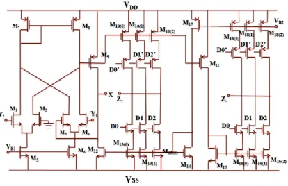
[image:4.595.74.284.492.584.2]In this section the proposed digitally programmable voltage-mode multifunctional biquadratic filter has been presented as shown in Fig. 6
Fig.6. Proposed Digitally controlled voltage-mode multi-function biquadratic filter
The introduction of the DC-DVCC comprising of CSN modifies the expression of pole-frequency ω0 of the multifunctional filter. The expressions for the digitally programmable filter responses can now be expressed as:
k
k
k
Resonant angular frequency ⍵o, and the quality factor Q are given as:
ω˳
k
⁄
√
Q =
√
6.
SIMULATION RESULTS
The proposed digitally controlled multifunctional biquadratic filter circuit in Figure 6 has been simulated and all the results are verified using PSPICE. Fig. 7(a) and 7(b) shows the simulated responses obtained for the low-pass, high pass, and
band-pass filters keeping the digital control word [d2 d1 d0] = [0 1 0] and [1 0 1].The 3-bit digital control word
is varied from [0 0 1] to [1 1 1] to obtain the variation in the cut off frequency of the multifunction filter. These simulated were recorded in Table 2 and were then plotted. Fig. 8(a), (b)
(13)
(16)
(17)
(14)
International Journal of Computer Applications (0975 – 8887) Volume 94 – No 15, May 2014
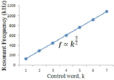
and (c) are the plots showing the variation in the cut off frequency with the control word. It is to be observed that the cut-off frequency showed a three by two variation with respect to the digital control word (k). Cut-off frequency varies from 128.03 kHz to 1.08 MHz for low-pass filter, 104.13 kHz to 1.36 MHz for high-pass filter, 112.62 kHz to 1.177 MHz for band-pass filter by varying the digital control word from [0 0 1] to [1 1 1], without changing the value of any of the passive components i.e. resistors and capacitors being used in the design.
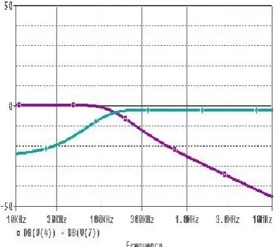
Fig. 7(a). Simulated magnitude responses (in dB) for control word [d2 d1 d0 = 0 1 0]
Fig. 7(b). Simulated magnitude responses (in dB) for control word [d2 d1 d0 = 1 0 1]
Fig. 8(a). Variation of Resonant Frequency of BPF with digital control word
Fig. 8(b). Variation of Cut-off Frequency of HPF with digital control word
[image:5.595.318.538.75.215.2]Fig. 8(c). Variation of cut-off Frequency of LPF with digital control word
Table 2. Simulated values of the variation in cut-off frequency with the control word
Control word, k
Cut-off frequency of
LPF (kHz)
Resonant frequency of
BPF (kHz)
Cut-off frequency of
HPF (kHz)
1 128.04 112.619 104.137
2 288.994 270.557 273.059
3 447.593 438.466 470.631
4 605.610 617.053 682.987
5 763.274 794.328 903.970
6 921.355 977.963 1130.79
[image:5.595.59.278.182.346.2] [image:5.595.319.538.274.424.2] [image:5.595.61.274.386.558.2] [image:5.595.321.536.519.710.2] [image:5.595.72.257.605.735.2]6
7.
CONCLUSION
In this paper, a digitally programmable voltage-mode multifunctional biquadratic filter based on three DVCCs was presented. Digital control has been achieved by the variation of 3-bit digital control word using a current summing network. Cut-off Frequency (ω˳) was digitally controlled by the 3-bit digital control word (k) and three by two variations with respect to the control word was observed. Standard low-pass, high-pass and band-pass filter responses were obtained simultaneously and their cut-off frequency was varied with digital control word. PSPICE simulations were carried out to verify the working of the digitally controlled multifunctional biquadratic filter. Thus as a result we obtained a multifunctional biquadratic filter giving low-pass, high-pass and band-pass filter responses of varying cut-off frequency at the same time without changing any of the circuit components or the topology. It is clear with the simulation figures shown that the filter responses have different cutoff frequencies for different k, Table 2 and plots 8 (a), (b) and (c), prove that the obtained results confirm the theoretical relations derived.
8.
REFERENCES
[1] H. Y. Wang, C. T. Lee. “Versatile insensitive current-mode universal biquad implementation using current conveyors.” Circuits and Systems II: Analog and Digital Signal Processing, IEEE Transactions, vol. 48, issue. 4, pp. 409-413, Apr. 2001.
[2] H. Hakan Kuntman. “New Advances and Possibilities in Active Circuit Design.” in Proc. 10th International Conference on Development and Application Systems, 2010, pp. 9-18.
[3] B. Wilson, “Recent developments in current conveyors and current-mode circuits.” Circuits, Devices and Systems, IEE Proceedings G, vol. 137, issue. 2, pp. 63-77, Apr.1990.
[4] A.S. Sedra, K.C. Smith. “A second generation current conveyor and its applications”. IEEE Transactions on circuit theory, vol. 17, pp.132-134, Feb. 1970.
[5] W. Chiu, S. I. Liu, H. W. Tsao, J. J. Chen. “CMOS differential difference current conveyors and their
applications.” IEE Proceedings-Circuits, Devices and Systems, vol. 143, issue. 2, pp. 91-96, Apr. 1996. [6] H.O. Elwan, A. M. Soliman. “Novel CMOS differential
voltage current conveyor and its applications.” IEE Proceedings-Circuits, Devices and Systems, vol. 144, issue. 3, pp. 195-200, Jun. 1997.
[7] H. Sedef, C. Acar. “A new floating inductor circuit using differential voltage current conveyors.” Frequenz , vol. 54, issue. .5-6, pp. 123-125, 2000.
[8] S. S. Gupta and R. Senani, ''Grounded-capacitor current-mode SRCO: novel application of DVCC'', Electronics Letters, vol. 36, issue. 3, pp. 195-196, 2000.
[9] T. Dostal, D. Biolek, K. Vrba. “Adjoint voltage-current mode transformation for circuits based on modern current conveyors.” Devices, Circuits and Systems, Proceedings of the Fourth IEEE International Caracas Conference, 2002, pp. T034-1.
[10]S. Minaei,Ç. Temizyürek. “Dual input all-pass filter using DVCC.” International Symposium on Signals, Circuits & Systems (SCS), vol. 2, pp. 477-480, Jul. 2003. [11]J. W. Horng, C. L. Kaewpoonsuk, C. M. Chang, H. P.
Chou, C. T. Lin. “High input impedance voltage-mode universal biquadratic filter with one input and five outputs using current conveyors.” Circuits, Systems and Signal Processing, vol. 25, issue. 6, pp. 767-777, Dec. 2006.
[12]W. Tangsrirat , O. Chaannumsin. “Voltage -mode multifunctional biquadratic filter using single DVCC and minimum number of passive elements”. Indian Journal of Pure and Applied Physics, vol. 49, pp.703-707, Oct. 2011.
![Fig.2. CMOS realization of the dual-output DVCC [12]](https://thumb-us.123doks.com/thumbv2/123dok_us/8045044.772438/2.595.100.523.77.344/fig-cmos-realization-of-the-dual-output-dvcc.webp)