REVISION RECORD
REVISION
DESCRIPTION
01 Preliminary manual released. 11J1/70
02 Latest technical information added.
5/1/71
A All textual corrections made and equipment sketches updated.
7/15/72
Publication No,
48430070
© 1971, 1972
by Control Data Corporation
Printed in the United States of America
o
. , . ...
. ,.: :
.'
" ~I
.i·:·i:'·;·
Address comments concerning this manual to:
Control Data Corporation
0
OCR Operations1455 Research Boulevard Rockville Maryland 20850
CONTENTS
C
1
GENERAL DESCRIPTION
1
Sort Pockets
8
System Operation
1
Optics System
8
Light Source
8
Operator Controls and Indicators
2Read Station
8
2
THEORY OF OPERA TION
5
Scanning System
8
Folded Optics
9
Document Transport System
5
Light Pipe Array
10
•
Feed- Up Table
5
Character Recognition System
10
Feeder
6Supporting Systems
10
Edger
6Vacuum System
10
Conveyor
6Cooling System
10
Document Sensor System
6Power Distribution System
11
Velocity Servo Drive System
7
Maintenance System
11
Takeaway Unit
8
APPENDIX
Sort Gate
8
13
FIGURES
1
955 Page and Document Reader
iv
5
Document Transport System
-2
Data Flow - Reader to Tape
1
955 Reader
5
3
955 Operator Control Panel
2
6Document Sensor Locations
-4
Document Adjustment Panel -
955 Reader
7
C
955 Reader
4
7
Optics System - 955 Reader
9
TABLES
1
Operator Control Panel
3
5
955 Reader Operational
2
Document Adjustment Panel
4
Specifications
15
3
955 Reader Options
13
6Reader Physical CharaFteristics
17
*'"
co*'"
w oo
-.::Jo
>
~
~~
OPERATOR CONTROL PANEL
[image:4.791.105.742.39.587.2]o
Figure
1.
955 Page and Document Reader
r'J
..
CONTROLLER MODULE
c
SECTION 1GENERAL DESCRIPTION
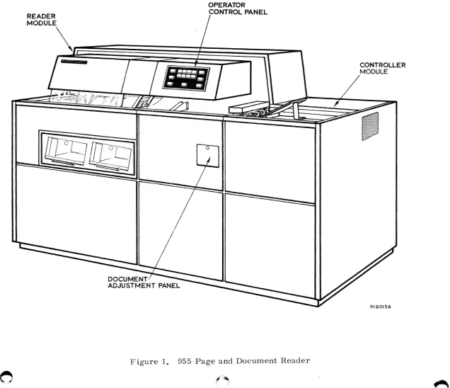
The CONTROL DATA® 955 Page and Document Reader is a peripheral device that optically reads printed pages and documents. recognizing the full American National Standards Institute (ANSI) OCR-A size I upper case character set. Data may be printed by typewriter. high speed printer. or embossed card imprinter. External controls and design features of the reader are shown in Figure 1.
Descriptions of system operations and operator controls and indicators are contained in this section. Section 2 contains the theory of operation of the reader and its sUbsystems. Optional fonts. a listing of reader-compatible software programs. operational specifications. and a physical description of the reader are contained in the appendix.
SYSTEM OPERATION
A block diagram showing data flow from reader to magnetic tape transport comprises Figure 2. Documents are loaded into a feed-up table on the reader. transported individually to the read area. and scanned line-by-line. The combination of the mirror movements in the lens system causes each character read to be broken into a series of light and dark elements. Photomulti-pliers convert these light and dark images into electrical impulses. A shift register receives these signals and "rebuilds!! the character electronically. After all characters in a line are read in this analytical fashion. the document is advanced and the next line is read. When all lines on a document are read. the document is sorted to the primary output hopper. If the document is rejected for any of a variety of reasons. it is routed to the secondary output hopper.
SENSE DATA SENSE DATA STATUS,
READER CONTROL CONTROLLER CONTROL
-
COMPUTER-
DATA TELETYPEWRITERCONTROL
1
MAGNETIC TAPE CONTROL MAGNETIC TAPE
TRANSPORT ~ONTROLLER
R!QOO!B
Figure 2. Data Flow - Reader to Tape
[image:5.612.51.578.368.766.2]Signals from the controller enable document movement. reading. and sorting. Data is routed to the controller from the reader. along with sense signals indicating reader status. The general purpose digital computer is programmed to control system operation and to provide output data in a format established by the user. Communication from the computer to the reader controller and the magnetic tape controller. and between the computer and the teletype-writer. is maintained over one-way or bi-directional data and status channels. as indicated. Teletypewriter communication with the computer enables effective program control and prompt diagnosis of malfunctions. A magnetic tape transport enables loading of the program into the computer and stores data from the optically scanned documents onto magnetic tape for further processing. The magnetic tape controller interfaces the computer with the magnetic tape transport.
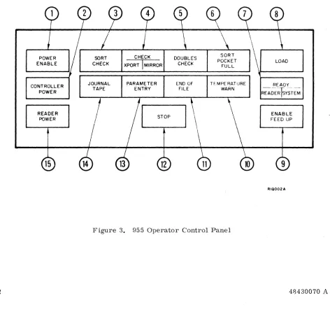
OPERA TOR CONTROLS AND INDICA TORS
The operator should be familiar with the operator control panel (Figure 3) on the reader. Controls and indicators on the operator control panel are described in Table 1; those on the document adjustment panel are described in Table 2. Location of the two panels is shown in Figure 1.
2
CONTROLLER POWER
READER POWER
15
JOURNAL TAPE
PARAMETER , ENTRY
STOP
12
END OF FILE
TEMPERATURE WARN
Figure 3. 955 Operator Control Panel
READY
~~~~Ts~S~EM
RIQ002A
48430070 A
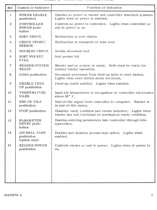
[image:6.612.63.535.292.748.2]TABLE 1. OPERATOR CONTROL PANEL
Ref Control or Indicator
1 POWER ENABLE
pushbutton 2 3 4 5 6 7 8 9 10 11 12 13 14 15 CONTROLLER POWER push-button
SORT CHECK
CHECK XPORT / MIRROR
DOUBLES CHECK
SORT POCKET FULL
READER/SYSTEM READY
LOAD pushbutton
ENABLE FEED UP pushbutton
TEMPERA TURE WARN
END OF FILE pushbutton
STOP pushbutton
PARAMETER ENTRY push-button
JOURNAL TAPE pushbutton (option only)
READER POWER pushbutton
Function or Indication
Enables ac power to reader and controller interlock systems. Lights when ac power is enabled.
Controls ac power to controller. Lights when controller ac and dc power is on.
Malfunction at sort station
Malfunction in transport or scan area
Double document feed
Sort pocket full
Reader and/ or system is ready. Both must be ready for normal reader operation.
Document movement from feed-up table to read station. Lights when read station needs document.
Feed-up clutch enabled. Lights when enabled.
Input air temperature to recognition or controller electronics above 80° F.
End-of-file signal from controller to computer. Reader is in end-of-file status.
Disables ready condition and resets indicator. Lights when reader has lost functional or mechanical ready condition.
Enables entering parameters into controller through tele-typewriter.
Enables and disables journal tape option. Lights when enabled.
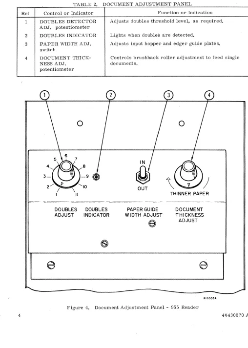
[image:7.612.47.549.81.751.2]TABLE 2
.
DOCUMENT ADJUSTMENT PANELo
Ref Control or Indicator Function or Indication
1 DOUBLES DETECTOR Adjusts doubles threshold level. as required. ADJ. potentiometer
2 DOUBLES INDICA TOR Lights when doubles are detected.
3 PAPER WIDTH ADJ. Adjusts input hopper and edger guide plates. switch
4 DOCUMENT THICK- Controls brushback roller adjustment to feed single
NESS ADJ. documents.
potentiometer
C
'.
;_9
)
OUT
THINNER PAPER
---_.
-DOUBLES DOUBLES PAPER GUIDE DOCUMENT
ADJUST INDICATOR WIDTH ADJUST THICKNESS
e
ADJUST~
e
e
RIQOOaA
c
Figure 4. Document Adjustment Panel - 955 Reader
[image:8.612.69.577.43.756.2]c\
•
I".:
~/
SECTION 2
THEORY OF OPERATION
The reader converts printed, typed, or handprinted data into digital information for computer processing. The major systems which accomplish reader functions are:
• document transport system • optics system
• character recognition system • supporting systems
The document transport system moves each document from the feed-up table to the read area, and advances it a line at a time until the entire document is scanned. It then moves each docu-ment from the read area through the takeaway unit and sorts it into one of two sort pockets.
The optics system scans each line of text on the document as it is advanced through the read area. Scanned characters are recognized by the character recognition system which then out-puts corresponding digital information to the controller. The controller also functions as an integral part of the reader timing and control logic.
The supporting systems cover vacuum-pressure, cooling, power distribution, and maintenance requirements.
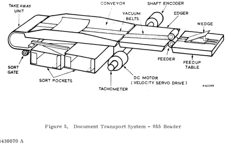
DOCUMENT TRANSPORT SYSTEM
The document transport system, Figure 5, consists of feed-up table, feeder, edger, conveyor, document sensor system, velocity servo drive system, takeaway unit, sort gate, and two sort pockets.
TAKEAWAY UNIT
1
SORT GATE
CONVEYOR SHAFT ENCODER
I
SORT POCKETS ( VELOCITY SERVO DRIVE) DC MOTOR
RIQOOaB
TACHOMETER
[image:9.612.86.539.427.762.2]I ,
FEED-UP TABLE
Documents, loaded face up into the feed-up table with leading edges toward the feeder, are fed from the top. A wedge, mounted on the feed-up table belt drive, positions the documents for proper feeding. The belt, driven by a clutch and constantly running motor, carhes the docu-ments to the feeder, where a sensor energizes the clutch as they near the feeder rollers. The ENABLE FEED UP pushbutton indicator deenergizes the clutch during loading. With the feed-up belt at rest, the wedge is pulled back to accommodate additional documents. The PAPER WIDTH ADJ. switch positions the guide plates to the paper width.
FEEDER
The feeder consists of three roller assemblies. The feed-in roller moves the document toward the feeder roller assembly, positioned over a brushback roller. When the paper contacts both rollers, the feeder roller's higher coefficient· of friction drives the paper forward. When mul-tiple documents are carried forward, the lower one contacts the brushback roller and is driven back toward the feed-up table, since the paper-to-paper friction is less than the friction of the brushback roller to paper. Thus only one document at a time is fed from the top of the stack to the edger.
Vertical positioning of the brushback roller, adjusted by the DOCUMENT THICKNESS ADJ. knob, is sometimes needed to compensate for variations in paper thickness.
The same motor drives the feeder roller assemblies, the document conveyor, and the edger. Inter-document gap develops because the linear speed of the feeder rollers is about seven
o
percent less than that of the edger and conveyor belts. ( "
EDGER
The edger centers and squares the document moving from the feeder into the conveyor. The edger vacuum belt, slightly inclined and driven at the same speed as the conveyor, carries the document to the left edging wall, parallel to the conveyor centerline. The document moves along the wall and is squared with the conveyor. A plastic cover at the edging wall inhibits buckling and facilitates the desired edging action. The PAPER WIDTH ADJ. switch moves the edging wall simultaneously with the feed-up table guide walls for precise document centering.
CONVEYOR
The document is conveyed by friction on a two-inch vacuum belt driven by the velocity servo drive system. Vacuum holds the document flat during transport, and mylar fingers maintain flat positioning at the read station, where the concave conveyor is accurately located for scanning. The conveyor system stops the document for each line scan, then steps it rapidly to the next line.
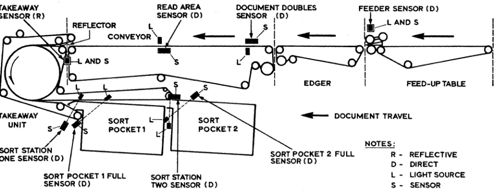
DOCUMENT SENSOR SYSTEM
The document sensor system signals document position and status to the controller. Location of the various photosensor-light units is shown in Figure 6.
6 48430070 A
TAKEAWAY SENSOR (R)
READ AREA DOCUMENT DOUBLES FEEDER SENSOR (D)
I SENSOR (D) SENSOR 1(0)
!
I
REFLECTOR L i s ,liJ-
L AND SI
_u..~~~n
CONVEYOR'. ... . . . . - - -J.(
I "
~
"s
~. I~I~
TAKEAWAY
S O : ' : A T I l . j - -_ _ _ _ .J
ONE SENSOR (D)
SORT POCKET 1 FULL SORT STATION
SENSOR (D) TWO SENSOR (D)
,
I
I
I EDGER I FEED-UP TABLE I
. . . . - - DOCUMENT TRAVEL
SORT POCKET 2 FULL SENSOR (D)
NOTES:
R - REFLECTIVE 0- DIRECT L - LIGHT SOURCE S - SENSOR
Figure 6. Document Sensor Locations - 955 Reader
The feed-up sensor uses a metal flag mounted on the yoke of the feeder pickup rollers between the photosensor and light source. As the stack of documents contacts the feeder roller
assembly. causing the assembly to rise. the metal plate moves out from between the photo-sensor and light source. Triggered by the light. the photophoto-sensor sends a document-at-feeder message to the reader logic. This deenergizes the feed-up clutch and stops the feed-up belt.
If more than one thickness of paper passes between the document doubles sensor and its light source. a signal is sent to the controller. The controller actuates the DOUBLES CHECK indi-cator to stop the conveyor drive system until correction is made. The DOUBLES DETECTOR ADJ. control adjusts the photosensor for different types of paper.
A document-ready sensor. one inch before the centerline of the read station, generates a document-ready signal to the controller. and actuates the TOTAL DOCUMENTS counter. Sort entry. sort station 1. sort pocket 1 full. sort station 2. and sort pocket 2 full photosensors signal the controller for sort control. sort pocket full. and paper jam detection.
VELOCITY SERVO DRIVE SYSTEM
This system drives the feeder. edger. and conveyor units through a series of timing belts, pulleys. and tensioners. The system operates under user software instructions from a pro-gram resident in the controller, subject to status signals from the sensors and the panel. The system is powered hy a dc servo motor. A tachometer generator fixed to the motor shaft pro-vides feed-back sigr,als. and a shaft encoder furnishes position signals to the controller for every O. 008-inch 01 ~elt travel.
The document transpurt system advances the conveyor belt for line-by-line document scan control. Controlle transport commands. directed by the computer. include forward speeds of 5, 12.5. 20. anc .0 inches per second. and a reverse speed of 5 inches per second.
[image:11.612.59.540.98.287.2]TAKEAWAY UNIT
This device. transporting documents from the conveyor to the sorter. consists of a pair of belts (one of which is a vacuum belt). drum. motor. and associated drive pulleys and bearings. The takeaway belts are driven at a constant 68 inches per second. As a document leaves the read station. the rollers and belts convey it into one of two sort pockets.
SORT GATE
Controller signals direct the solenoid-operated sorting gate to either carry a document to sort pocket 2 or to peel it off the takeaway vacuum belt and drop it into sort pocket 1.
SORT POCKETS
The two five-inch capacity sort pockets have adjustable side and end guides to align and stack the output documents without jamming. The end guides are mechanically converted. so
adjustment of one sets both to proper length. The pocket width guides must be set individually. I
OPTICS SYSTEM
The optics system enables scanning of each line and transmits scanned images to an array of photomultipliers for conversion to electrical signals and processing by the electronic recog-nition system. The optics system components and functions are illustrated in Figure 7.
LIGHT SOURCE
Illumination is provided by a single sun-gun type of lamp which normally operates at less than 80 percent of its rated 650 watts. This reduced power greatly increases lamp life while pro-viding adequate light. A variac adjusts the lamp supply voltage to compensate for variations in line voltage and aging of the lamp. The light is reflected by a mirror onto the document surface. This illuminating mirror is attached to the same shaft as the scanning mirror to provide a moving spot of light synchronized to the spot being scanned.
READ STATION
The document is scanned on the concave surface at the read area. The surface of the scanning mirror is located at the center of radius of the read area arc.
SCANNING SYSTEM
The scanning system is driven by a velocity dc motor servo system. A shaft encoder provides position signals to the controller for every 0.048 inch of scan travel at the paper. The tacho-meter provides voltage feedback information to the servo drive system. The servo system operates under control of user instructions from a program resident in the controller and status and control logic in the reader.
The system scans
a.
line of characters from left to right (facing direction of paper travel) at a constant velocity of 75 inches per second. In the reverse or flyback direction (right to left). the scanning mirror flies back at high speed and stops at the desired coordinate. This mode of operation enhances document throughput because the document advances during flyback time and the next line is in position for scanning when flyback is complete. Scanning can also be done right to left with flyback in the reverse direction.8 48430070 A
(l
t
FOLD MIRROR
\\
SHAFT
I
ENCODERFOLDED OPTICS
-_.
ILLUMINATING MIRROR- _._
---_.-SUN GUN
LAMP
SCANNING MIRROR
I
~
READ STATION
Figure 7. Optics System - 955 Reader
TACHOMETER
'''QQIOA
[image:13.612.60.539.67.597.2]LIGHT PIPE ARRAY
Each light pipe transmits a portion of the image to a photomultiplier tube that converts the
light and dark image elements into electrical signals for processing by the recognition system. . For reading ANSI size IV characters (optional), a second set of light pipes and a
program-controlled electromechanical shutter are added so the proper light pipes can be selected. Thus with the ANSI size IV option installed, either size I or size IV characters can be recognized by suitable programming.
CHARACTER RECOGNITION SYSTEM
The character recognition system analyzes scanned character images and outputs corres-ponding character codes to the controller. The light pipes transfer light and dark elements of the character from the scanning system to the photomultiplier assembly, which converts the light signals into electrical analog signals. Quantizer circuits convert the analog signals to digital signals corresponding to light or dark elements of the character. The digitized character image is then reconstructed in a shift register.
The quantized signals are applied to the shift register through load and accumulator registers. In effect. the shift register electronically reconstructs the scanned character by sampling the black and white characteristics of the character, one column at a time, and then storing 15 of these columns in the shift register. Each video information bit is shifted through every possible position in the shift register so that the character eventually is correctly positioned to determ:ine its identity.
The output of the shift register is applied to resistor-diode matrices, one for each character to be recognized. These matrices function as stored electronic images. When the character is fully loaded into the shift register, each matrix outputs a voltage proportional to the
similarity between its stored image and the scanned character. If the stored image and the scanned character are dissimilar, the voltage is very small. The greater the similarity, the closer the output voltage to the ideal. The matrix which most closely matches the character produces the most nearly ideal voltage. The matrix outputs are applied to the comparator circuits to determine the best match between the scanned image and the stored images. The character matrix output with the best match voltage "wins" and is therefore the character recognized. A 7-bit ASCII code representing the recognized character is generated by the encoder and transmitted to the controller.
SUPPORTING SYSTEMS
The supporting systems provide for vacuum, cooling, power distribution, and maintenance.
VACUUM SYSTEM
Vacuum provided to the transport system aids in document separation, holddown, and control. The 60 cfm nominal v!'lcuum flow rate serves the edger, stacker vacuum belts, conveyor dc drive motor (for cooling), and the conveyor vacuum belt.
COOLING SYSTEM
Cooling air is supplied to the reader to maintain an internal temperature below 1250 F. Fans
provide a high volume of cooling air flow over units to dissipate heat. A special system cools the read area and the conveyor servo drive motor. Two fans draw air from the read area and exhaust it at the top of the scan cover housing. The conveyor servo drive motor is cooled by
()
(
~.. - /
an air flow of 15 cfm, drawn through the motor by the vacuum system. .
C
c
POWER DISTRIBUTION SYSTEM
Power for the reader and controller is provided by separate ac and dc control and distribution systems.
MAINTENANCE SYSTEM
Built-in features aid in rapid system setup, testing. and identification. The system monitors voltages and signals within the reader and controller. Indicators provided for maintenance personnel reveal both software and hardware faults. Software and system diagnostics supple-ment the maintenance features.
o
#)
..
'-
....c
APPENDIX
READER OPTIONS
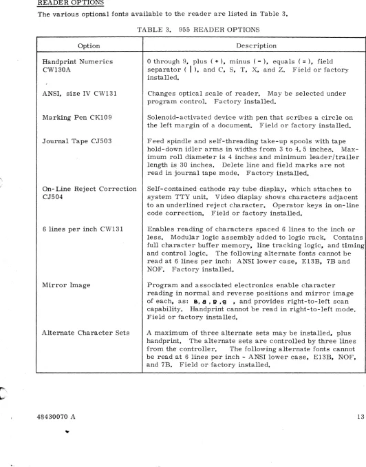
The various optional fonts available to the reader are listed in Table 3.
TABLE 3. 955 READER OPTIONS
Option Description
Handprint Numerics CW130A
ANSI, size IV CW131
Marking Pen CKI09
Journal Tape CJ503
On- Line Reject Correction CJ504
6 lines per inch CW131
Mirror Image
Alternate Character Sets
o
through 9, plus ( +), minus (-), equals (=), field separator (I ),
and C, S, T, X, and Z. Field or factory installed.Changes optical scale of reader. May be selected under program control. Factory installed.
Solenoid-activated device with pen that scribes a circle on the left margin of a document. Field or factory installed.
Feed spindle and self-threading take-up spools with tape hold-down idler arms in widths from 3 to 4. 5 inches. Max-imum roll diameter is 4 inches and minimum leader/trailer length is 30 inches. Delete line and field marks are not read in journal tape mode. Factory installed.
Self-contained cathode ray tube display, which attaches to system TTY unit. Video display shows characters adjacent to an underlined reject character. Operator keys in on-line code correction. Field or factory installed.
Enables reading of characters spaced 6 lines to the inch or less. Modular logic assembly added to logic rack. Contains full character buffer memory. line tracking logic. and timing and control logic. The following alternate fonts cannot be read at 6 lines per inch: ANSI lower case, EI3B, 7B and NOF. Factory installed.
Program and associated electronics enable character reading in normal and reverse positions and mirror image of each, as: 8, B , S
,ca •
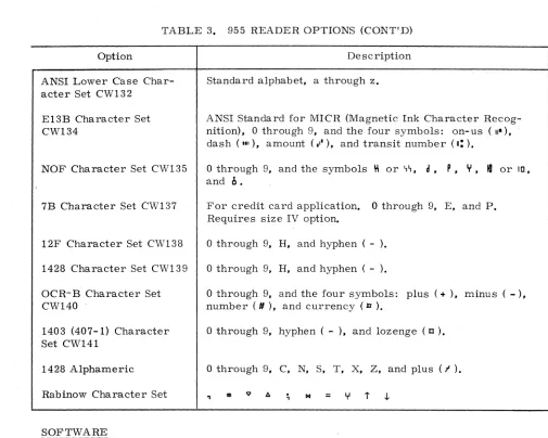
and provides right-to-left scan capability. Handprint cannot be read in right-to-left mode. Field or factory installed. [image:17.612.26.558.104.782.2]TABLE 3. 955 READER OPTIONS (CONT'D)
Option Description
ANSI Lower Case Char-acter Set CW132
E13B Character Set CW134
NOF Character Set CW135
7B Character Set CW137
12F Character Set CW138
1428 Character Set CW139
OCR-B Character Set CW140
1403 (407-1) Character SetCW141
1428 Alphameric
Rabinow Character Set
SOFTWARE
Standard alpbabet, a through z.
ANSI Standard for MICR (Magnetic Ink Cbaracter Recog-nition), 0 through 9, and the four symbols: on-us (II"), dash ('11), amount (,"), and transit number (I: ).
o
through 9, and the symbols ~ or ~~,d, P, Y, 10
or Ill,and
b.
For credit card application. 0 through 9, E, and p. Requires size IV option.
o
through 9, H, and hyphen ( - ).o
through 9, H, and hyphen ( - ).o
through 9, and the four symbols: plus (+ ), minus ( - ), number ( II), and currency (ti ).o
through 9, hyphen ( - ), and lozenge (Il ).o
through 9, C, N, S, T, X, Z, and plus (f )..,
... =Y
t ,j.The various software programs developed by Control Data Corporation for use with this reader are listed in Table 4. Reader specifications are shown in Table 5.
The reader controller (FF104) provides the interface between the 955 reader and the 1700 computer system. It is programmable, not hard wired, and controls the operation of the reader and communication with the user system.
14 48430070 A
()
[image:18.612.49.554.50.454.2]•
,C'·"
"TABLE 4. 955 READER SOFTWARE
Program Function
GRASP (Generalized Read
And Simulate Program)
DRAFT (Document Read
And Format Translator)
SETUP (Source Edit and Tape Update Program)
Tape SCOPE (Supervisory Control of Program Execution)
TABLE 5.
ITEM
Paper Weight
Paper length
18 to 24 pound paper 24 to 38 pound paper
Paper width
18 to 24 pound paper 24 to 38 pound paper
Enables user to specify reading of documents in multiple formats, and to insert headers or constants within output data records, as well as choose the desired magnetic tape output format.
Enables user to compile and execute an object program from optically read source statements and data, using a program that includes assembly language statements and such special features as pen marking, handprint. and reading of mirror image characters.
Enables user to write an assembly language or DRAFT source statement program onto magnetic tape as 80-char-acter records. Source programs previously written on tape may be added, updated, or deleted, control statements added for program maintenance, and new source statements added.
This system monitor provides full capability for source program editing, including assembling. loading, execution. and debugging, as well as modification to both system and user library tapes.
955 READER OPERA TIONAL SPECIFICA TIONS
SPECIFICA TIONS
18 to 38 pounds
3-1/4 to 12-5/8 inches 3-1/4 to 5-1/4. inches
4-7/8 to 11-1/8 inches 4-7/8 to 8-1/2 inches
Aspect (length/width) ratio 0.64 minimum except 3-1/4 by 7-3/8 inches standard tab cards or other sizes approved in advance by OCR Operations.
Double-feed prevention
Input hopper capacity Cards
Pages
Brushback roller on feeder. Photoelectric doubles detector at conveyor entry senses double-fed document and stops transport.
[image:19.612.42.568.75.740.2]TABLE 5. 955 READER OPERA TIONAL SPECIFICA TIONS (CONT'D)
ITEM SPECIFICA TIONS
Controller selected paper transport velocity
Forward Reverse
Type font standard
Space generation
Instantaneous reading rate
Scan rate
Power input voltage
955 reader input current (59 - 60. 6 Hz)
Operating Start-up Standby Operating power Ambient temperature range Operating Storage
Relative humidity Operating Storage
Heat dissipation
Altitude
16
5, 12.5, 20, and 40 inches per second 5 inches per second
ANSI alphameric set includes upper case A through Z,
o
through 9, and the symbols: comma ( .. ), period ( . ), doJlar sign ( $), ampersand ( &), 'slant (/), dash (- ),asterisk (* ), percent (% ), hook ( J'), up fork ( Y), chair (
n),
character delete ( 1:), field mark (
I ),
line delete ( ), colon ( : ), equals (=), plus ( +), left parenthesis ( {), right parenthesis (}), question mark ( ?), semicolon (; ), quota-tion mark ( "), and apostrophe ( ~ ).Spaces can be generated up to a maximum of twenty. Space generation can be selected for reading at seven, eight, or ten character spaces per inch.
750 characters per second at 10 characters per inch pitch.
75 inChes per second.
208 ±10%, 30 amps/phase with ac neutral and earth ground (5 WIRE).
12 amps per phase
200 amps per phase, single cycle 2 amps, single phase
4.1
kva
600 to 800 F.
300 to 1500 F.
30% to 60%
5% to 950/0 (no condensation)
14,000 BTU/hour
-1. 000 ft. to 6, 000 ft. above mean sea level.
48430070 A
o
[image:20.612.20.600.41.774.2]PHYSICAL DESCRIPTION
The reader is housed in a pair of welded-frame modules bolted together. Casters and adjust-able feet are provided. Physical characterist:ics are listed in Tadjust-able 6.
TABLE 6. READER PHYSICAL CHARACTERISTICS Weight
Reader module Controller module
Dimensions
Reader module height width depth
Controller module height width depth
Reader assembled height width depth
1400 lb. 400 lb.
57 inches 72 inches 34 inches
48-1/2 inches 26-1/4 inches 34 inches
[image:21.612.85.532.133.755.2]o
..
C
'"
Z ..I ellZ
0
....
c
....
:::t
U
·CD
COMMENT SHEET
MANUAL TITLE __
~9~5~5~P~a~g~e~a~n~d~D~o~c~u~rn~e~n~t~R~e~a~d~e~r~~T~h~e~o~r~y~o~f~O~p~e~ra=t~i~o~n~____ __
PU
aLi
C AT ION NO" _ _
4_84_3_0_0'_70
_ _ _ _ _
_
REV I S ION _ _
A _ _ _ _ _ _
_
FROM:
NAME~______________________________________________ __
BUSINESS
ADDRESS: ____________________________________________ __
COMMENTS:
This farm Is not Intended to be used as an order blank, Your evaluation of this manual will be welcomed by Control Data Corporation,. Any errors, suggested additions 01 deletions or general comments may be made below, Please Include page number references,
STAPLE
FOL 0 FO L 0
- - - -
- - - 1
FIRST CLASS
PERMIT NO. 8241
MINNEAPOLIS, MINN.
BUSINESS REPLY MAIL
NO POSTAGE STAMP NECESSARY IF MAILED IN U. S.A.
POSTAGE WILL BE PAID BY
CONTROL DATA CORPORATION
OCR OPERATIONS 1455 RESEARCH BLVD.
ROCKVILLE, MARYLAND 20850
I
I
I
I
I
ATTN: TECHNICAL PUBLICATIONS :
- -
- -
-~- - - -
- - ---4
:OLD FOL D
I
I
I
I
I
I
I
I
I
I
I
I
I
I
I
I
w
Z
-'
...
Z Q -'
C