N A N O E X P R E S S
Open Access
Stable Single-Mode Operation of
Distributed Feedback Quantum Cascade
Laser by Optimized Reflectivity Facet
Coatings
Dong-Bo Wang
1,2, Jin-Chuan Zhang
1*, Feng-Min Cheng
1,2, Yue Zhao
1,2, Ning Zhuo
1, Shen-Qiang Zhai
1,
Li-Jun Wang
1,2, Jun-Qi Liu
1,2, Shu-Man Liu
1,2, Feng-Qi Liu
1*and Zhan-Guo Wang
1Abstract
In this work, quantum cascade lasers (QCLs) based on strain compensation combined with two-phonon resonance design are presented. Distributed feedback (DFB) laser emitting at ~ 4.76μm was fabricated through a standard buried first-order grating and buried heterostructure (BH) processing. Stable single-mode emission is achieved under all injection currents and temperature conditions without any mode hop by the optimized antireflection (AR) coating on the front facet. The AR coating consists of a double layer dielectric of Al2O3and Ge. For a 2-mm laser cavity, the maximum output power of the AR-coated DFB-QCL was more than 170 mW at 20 °C with a high wall-plug efficiency (WPE) of 4.7% in a continuous-wave (CW) mode.
Keywords:Quantum cascade laser, Distributed feedback, Facet coating, Stable single mode
Background
Mid-infrared quantum cascade lasers (QCLs) [1] are one of the most promising light sources for many commercial ap-plications. These practical applications such as gas sensing, free-space communication, and high-resolution spectros-copy [2–5] would require QCL with high power, improved single-mode reliability, and low cost. As a result, since the first distributed feedback (DFB)-QCL was demonstrated in 1997 [6], the performance of these devices has been made strong improvements with the demonstration of room temperature continuous-wave (CW) operation with high power across the mid-infrared region [7–10]. However, most DFB-QCLs based on buried grating structure would have the problem of random cleaved facets that determine lasing frequency mode. Due to the same amount of loss in two band-edge modes, stable single-mode operation cannot be guaranteed [11]. Especially under high temperature
condition or large injection current, mode hopping always happens which is detrimental for the applications in these single-mode devices.
To get a stable single-mode operation, a quarter-wave phase shift (λ/4 PS) was introduced in grating period so that the laser can work in defect mode; thus, competition between the two band-edge modes can be avoided. But electron beam lithography must be used for the fabrication of λ/4 PS grating, which is time-consuming and expensive [12]. Gain-coupled DFB laser is a good choice to achieve stable single-mode operation for conventional semiconductor laser [13]. However, it is unrealistic for QCL to make the gain-coupled DFB lasers because of the great loss caused by etched active region. Another artful method is to use the cavity loss coupling mechanism for in-creasing the difference loss between two DFB modes. It is believed that appropriate reflectivity facet coating can achieve stable single-mode operation at even high temperatures and large currents. Although there are some researches devoted to facet coating, they al-ways focus on forming optimal equivalent cavity length Lopt to preserve wall-plug efficiency (WPE) for * Correspondence:[email protected];[email protected]
1Key Laboratory of Semiconductor Materials Science, Institute of
Semiconductors, Chinese Academy of Sciences; Beijing Key Laboratory of Low Dimensional Semiconductor Materials and Devices, Beijing 100083, China
Full list of author information is available at the end of the article
lasers rather than the single-mode reliability [14,15]. Also, the optimized reflectivity coating should be a promising way to solve the competitiveness between two DFB modes and interesting to be investigated systematically.
In this paper, stable single-mode operation of DFB-QCLs at λ~ 4.76 μm is presented after antireflection (AR)/high reflection (HR) coating. The AR coating con-sists of a double layer dielectric of Al2O3(380 nm) and Ge (33 nm). These devices display a very low threshold current density of 0.65 kA/cm2 at 20 °C. Single-mode emission with a side-mode suppression ratio (SMSR) above 26 dB is achieved up to a temperature of 90 °C in CW operation without any mode hopping. It is believed that anti-reflectivity coating on the front facet is very valuable for suppressing random phase of cavity facet.
Methods
Theory and Simulation
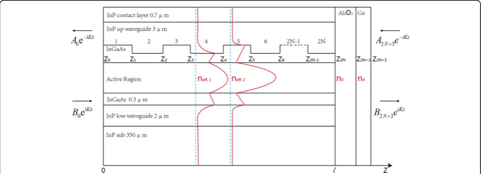
The core of simulation on antireflection coating effect in finite DFB cavity is the calculation of mode loss for two band-edge modes. Transfer matrix method would be an appropriate way to analyze the whole laser structure [16, 17]. We consider the application of this method to devices which have a longitudinal refractive index pro-file similar to that shown in Fig.1. This schematic drawing illustrates the effect of grating with small different effect-ive index perturbation (neff,1, neff,2) and coated films (n3, n4) on the guided mode. The complex refractive indexes of main materials used in calculation are listed as follows: InP (3.088 + i*2e−4), InGaAs (3.4 + i*2.9e−5), active region (3.298 + i*4e−5), high-doped InP (2.81 + i*1.4e−2), SiO2 (1.3603 + i*6.3e−4), Au (1.341 + i*32.582), Al2O3(1.5348 + i*3.2967e−3), and Ge (4.0165 + i*4e−2). Then, the different effective indexes neff,1= 3.1599 + i*5.17e−5 and neff,2= 3.1662 + i*5.6756e−5 were worked out with COMSOL through partial differential equation (PDE) function. The
laser is assumed to be operated in a single transverse mode so that propagation characteristics of light at each point along the laser cavity are described by a single scalar complex quantity, k, which is the wave vector of the medium. It is further considered that the laser is linearly polarized and its associated electric field has a sinusoidal time dependence eiωt. Following these assumptions given above, a one-dimensional plane electro-magnetic wave factorEz, which describes the part of special variation of wave function, satisfies the Helmholtz equation
∂2 Ez
∂z2 þK 2ð Þz
Ez ¼0 ð1Þ
K(z) is given by
Kð Þ ¼z ω
cnð Þ ¼z knð Þ ¼z ðkrþikiÞ nð Þz ð2Þ
where ω and c are respectively the angular frequency and light velocity and n(z) is the complex refractive index at each point along the laser cavity. The wave vector k which needs to be solved can be divided into two parts: kr and ki. The real part kr determines the wavelength of light in the laser cavity, while the imaginary part ki is originated from the mode loss of the finite cavity accounts for attenuation. From Fig. 1, it can be seen that the laser can be considered as a multi-section device with 2N+ 2 sections where N is the grating period. In each of these sections, the electric field En(z) is a linear combination of two counter propagating exponentially plane waves where one is decreasing with complex amplitude An and the other is increasing with Bn. The equation is de-scribed as follows:
[image:2.595.57.539.539.714.2]Enð Þ ¼z Anexpð−iKnzÞ þBnexpðiKnzÞ ð3Þ
In total, there are 2N + 3 interfaces. At each of these interfaces, both the electric field and its derivative with re-spect to the propagation direction must be equal on both sides of the interface. The equation is obtained as follows:
E2Nþ3ð Þz E02Nþ3ð Þz
¼2YNþ2 n¼0
M dð Þn EE00ð Þz
0ð Þz
¼ μ11 μ12 μ21 μ22
E0ð Þz E00ð Þz
ð4Þ
The transfer matrixM(dn) is given by
M dð Þ ¼n cosðknndnÞ
1
knn
sinðknndnÞ
−knn sinðknndnÞ cosðknndnÞ
2 4
3 5 ð5Þ
Considering that the electrically pumped laser is a self-oscillating device, there are no incoming waves from
outside the device. This results in the boundary condi-tionB0=A2N+ 3= 0, and the equation turns to
f ¼ikμ11þμ12k2−μ21þikμ22¼0 ð6Þ
Each value of the wave vectork can be obtained with the aid of Matlab through Eq. (6). The imaginary partski corresponding to losses of the cavity modes would help to analyze the AR coating effects.
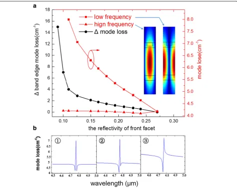
Figure2ademonstrates the calculated results based on transfer matrix simulation. As the two red curves have shown, the high-frequency mode loss changes very slowly with the decrease of reflectivity whereas the low-frequency mode increases sharply. The inset shows the mode profile calculated for the low- and high-frequency modes, for a sin-gle period of the grating. As plotted, the low-frequency mode has higher electric field magnitude in the grating peaks that is the higher index part of the grating, and also,
[image:3.595.65.290.167.272.2] [image:3.595.61.537.318.695.2]the high-frequency mode is more concentrated in the lower index part of the grating. For infinite cavity model without facet reflectivity, high-frequency mode always has lower mode loss than low-frequency mode. If the effect of end facet mirrors could be ignored, then the high-frequency mode with the smaller waveguide losses will always lase. However, the presence of end facet mirrors gives reflections that constructively or destructively interfere with the DFB modes in the laser cavity. This interference affects the finite grating-cavity loss of each mode and can determine which mode lases. We note that the effect of the mirrors is largest when the position of both mirrors coincide with a peak in electric field amplitude of one DFB mode, which is also when the mirrors are at a node for the other DFB mode. Here, the mirrors for the uncoated facet coincide with the peak of low-frequency mode, and then, the reflections from the end mirrors maximally constructively interfere with the mode present in the laser cavity. This results in a decreased total mode loss, due to the constructive contribution of the mirror. As the reflectivity decreases and additional phase shift influences by using the double layer AR coating, the loss of low-frequency mode gradually increased with the decrease of reflectivity due to the weakened interference effect and increased mirror loss. Meanwhile, the loss of high-frequency mode changed a little due to the enhanced interference effect. This results in that the Δ mode loss performs as similar as an exponential function especially when the front facet reflectivity is < 0.15. According to the simulation, there exits only one minimum point within whole spectrum when the reflectivity of front facet is < 0.11, which means that mode hop cannot hap-pen in theory because another band-edge mode loss is too high to lase.
Figure2bshows the three typical mode loss spectrums during simulation where the high- and low-frequency modes are 4.762 and 4.779 μm respectively. The first one is the DFB-QCL without AR coating. We can see the stopband originated from the grating feedback clearly, and the two band-edge modes are almost the same. The second one is specific AR coating with 200 nm Al2O3and 5 nm Ge with the reflectivity of 0.22. The differential between two band-edge modes begins to be obvious. The last one shows that with lower reflectiv-ity coating, the Δ mode loss is so big that the low-frequency mode submerged under the loss of stopband. Although the lower reflectivity, the greater Δmode loss in theory, we should also consider that the extremely low reflectivity causes huge mirror loss in devices which would make the WPE drop sharply. That is a trade-off to choose film thickness based on experiment.
Device Fabrication
The QCL wafer was grown on an n-doped (Si, 3 × 1017cm−3) InP substrate by solid-source molecular beam
epitaxy (MBE) based on a two-phonon resonance design. The active core includes 40 stages of strain-compensated In0.669Ga0.331As/In0.362Al0.638As quantum wells and bar-riers, which are similar to Ref. [18]. The layer sequence was as follows: 2-μm lower InP cladding layer (Si, 2.5 × 1016 cm−3), 0.3-μm-thick matched In0.47Ga0.53As layer (Si, 4 × 1016 cm−3), 40 active/injector stages, 0.3-μ m-thick In0.47Ga0.53As layer (Si, 4 × 1016cm−3), 3-μm upper InP cladding layer (Si, 2.5 × 1016 cm−3), and 0.7-μm highly doped InP cladding layer (Si, 5 × 1018cm−3). The average doping level of active region was empirically ad-justed to 2.4 × 1016cm−3. To fabricate the buried grating, the top cladding was removed down to the upper InGaAs layer. The first-order DFB grating with a period ofΛ= 0.755 μm (duty cycle σ= 20%) was defined on the 300-nm-thick upper InGaAs layer using holographic litho-graphic technique and subsequently etched to a depth of about 90 nm by wet chemical etching. Then, a 3-μm-thick low-doped (Si, 2.5 × 1016 cm−3) InP layer followed by a 0.2-μm gradually doped (changing from 1 × 1017 cm−3to 3 × 1017cm−3) InP layer and a 0.5-μm InP (5 × 1018cm−3) contact layer were accomplished in sequence as the upper cladding by metal organic vapor phase epitaxy (MOVPE).
Following implementation of the grating pattern and re-growth, the epi-wafer was etched into 10-μm-wide ridges, and then, the waveguides were reintroduced into the MOVPE system and buried in semi-insulating InP (Fe). A 450-nm-thick SiO2 layer was deposited by plasma-enhanced chemical vapor deposition (PECVD) for insulation around the ridge, and electrical contact was provided by a Ti/Au layer. An additional 5-μm-thick gold layer was subsequently electroplated to further im-prove heat dissipation. The waveguides were cleaved into 2-mm-long bars, and the testing was performed on devices with optimized reflectivity facet coatings. Both rear facet HR coating consisting of Al2O3/Ti/Au/Ti/ Al2O3 (400/5/100/10/200 nm) and the front facet AR coating consisting of Al2O3/Ge (380/33 nm) are depos-ited by e-beam evaporation. The calculated reflectivity of front facet is 3.4% for 4.76-μm wavelength, and the detailed relation between the fluctuation of coating thickness and reflectivity has been discussed in our previously published paper [19]. The lasers were mounted epilayer side down on SiC heat sinks with in-dium solder and then wire bonded to an external con-tact pad. For spectral and electrical characterization, the lasers are mounted on a Peltier element and the temperature was monitored on the heat sink with a thermistor.
Results and Discussion
the Bruker Vertex 70 FTIR and a nitrogen-cooled HgCdTe detector. The laser spectrum just above threshold indicates that the device operates on the fundamental mode and we can clearly get the stop-band of the fundamental mode when the current is 285 mA. From the stopband width Δν= 3.076 cm−1 and the effective index neff= 1/(2νΛ) = 3.153, we cal-culate a coupling coefficient κ=Δν·π·neff= 30.4 cm−1, resulting for our HR-coated 2-mm-long cavity in a coupling product κL of 12.1, which corresponds well with our device fabrication. The product of κL far
larger than the previous theoretical investigation κL≈ 1 [20] indicates that an overcoupled scheme is ob-tained, which is beneficial to secure single mode within the entire current and examined temperature range.
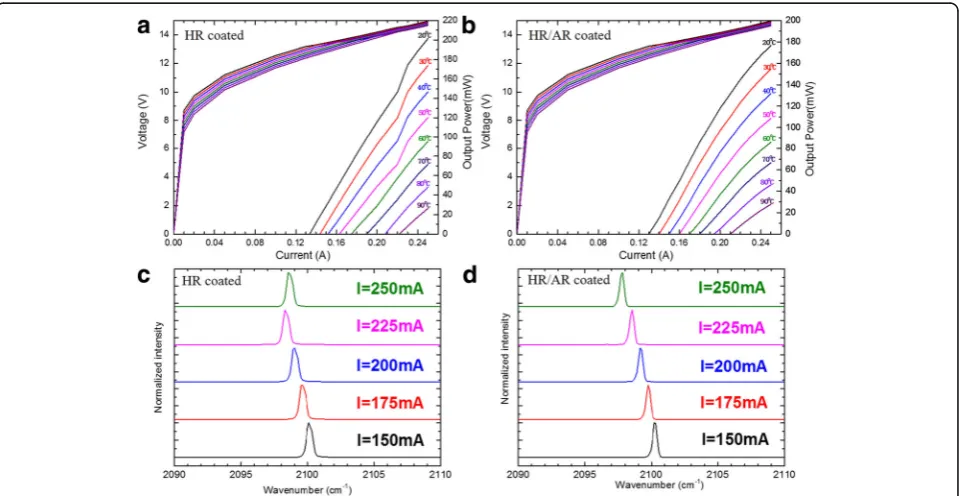
Figure 4a shows the typical CW power-current-voltage (P-I-V) curve of the DFB laser at different heat sink temperatures between 20 and 90 °C. The output power reaches 200 mW for the 2-mm-long device with a low threshold current density of 0.65 kA/cm2 at 20 °C. The threshold voltage (Vth) of 13.2–14.2 V was measured over the temperature range of 20–90 °C. It is worth noting that mode hop only exists in lower heat sink temperature below 60 °C which can be easily deduced from the P-I curve. High heat sink temperature would contribute more severe heat accumulation to the laser core so that thermal effect restrained another mode lasing and mode hop would not occur. Figure 4b shows the P-I-V curve of the DFB laser that an antireflection (AR) coating has been deposited on its front facet, and we choose an AR coating reflectivity of 3.4%. Every smooth P-I curves indicate that there is no mode hop existence all around the temperature we measured. Figure 4c, d shows the lasing spectral at different currents from 150 to 250 mA with a step of 25 mA. It is obvious from Fig. 4d that we achieve a stable single mode around different currents with optimized AR facet coating rather than mode hop in Fig. 3Subthreshold DC spectrum of device measured at 30 °C
[image:5.595.57.291.88.263.2] [image:5.595.59.539.455.703.2]Fig. 4c. The frequency always keeps a linear relation with injection current, and the current tuning coeffi-cient Δν/ΔI=−0.024 cm−1mA−1proves that AR coating is a simple and efficient method to solve the problem of mode hop in DFB-QCLs.
Figure 5 shows the emission spectra of the coating DFB laser at different heat sink temperatures from 20 to 90 °C. The measurements were performed using a NI-COLET 8700 FTIR spectrometer with 0.25 cm−1 reso-lution in a rapid scan mode. A single longitudinal mode emission is observed among the entire investigated temperature range with a side-mode suppression ratio (SMSR) 26 dB at high temperature of 90 °C. As is shown in the inset of Fig. 5, the peak emission spectrum was observed to shift from 2100.4 cm−1 at 20 °C to 2088.6 cm−1 at 90 °C, corresponding to a temperature tuning coefficient Δν/ΔT=−0.168 cm−1 K−1. The good linear tuning indicated that no mode hopping hap-pened during the change of heat sink temperature. In addition, all mentioned devices display a dominant single lateral far-field under CW operation on the fun-damental mode due to the accurate control of ridge width.
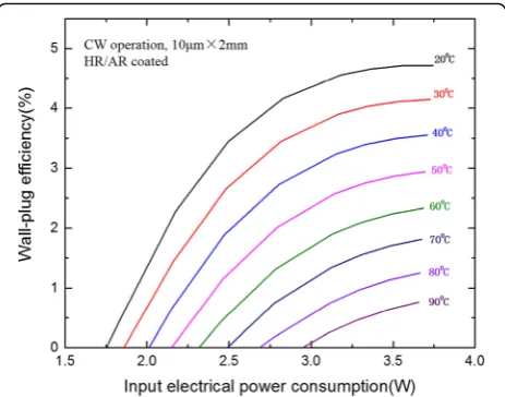
The CW WPE was calculated and plotted as a function of the input electrical power consumption in Fig. 6. At 20 °C, a maximum WPE of 4.7% was obtained around 240 mA with the output power of 170 mW. The maximum WPE were still 2.9 and 0.8% at 50 and 90 °C respectively. To date, these values were still very high for the low-threshold DFB-QCLs due to our high material quality and optimized reflectivity facet coating. It is believed that the WPE can be further improved by the optimized
selection of laser cavity lengths considering the coating effect.
Conclusions
We have demonstrated the room temperature CW operation of single-mode DFB-QCLs at λ~ 4.76 μm. By depositing AR coating consisting of double-layer dielectric Al2O3 and Ge on front facet, a stable single mode without any mode hop under all currents and temperature conditions has been realized successfully. At 20 °C, CW output power as high as 170 mW has observed with a very low threshold current density of 0.65 kA/cm2. Such devices represent an important step towards using stable single-mode operation of DFB-QCLs in mid-infrared spectral range for practical applications.
Abbreviations
AR:Antireflection; BH: Buried heterostructure; CW: Continuous wave; DFB: Distributed feedback; HR: High reflection; MBE: Molecular beam epitaxy; MOVPE: Metal organic vapor phase epitaxy; PDE: Partial differential equation; PECVD: Plasma-enhanced chemical vapor deposition;P-I-V: Power-current-voltage; QCL: Quantum cascade laser; SMSR: Side-mode suppression ratio; Vth: Threshold voltage; WPE: Wall-plug efficiency;λ/4 PS: A quarter-wave phase shift
Acknowledgements
We thank Ping Liang and Ying Hu for their help in device processing.
Funding
This work was supported by the National Basic Research Program of China (Grant No. 2017YFB0405303) and Beijing Natural Science Foundation (Grant No. 4172060).
Availability of Data and Materials All data are fully available without restriction.
Authors’Contributions
DBW designed the device structure, calculated the theoretical model, performed the testing, and wrote the paper. JCZ and FQL provided the concept, polished the paper, and supervised the project. FMC and YZ
Fig. 5Single-mode emission spectra of the DFB laser at a driving 1.1 threshold current for different heat sink temperatures of 20–90 °C. The insert shows the linearly fit tuning characteristics of the lasing frequency with temperature
[image:6.595.306.538.87.269.2] [image:6.595.58.290.505.683.2]fabricated the device. SQZ and SML improved the design. LJW and JQL completed the MOCVD growth. NZ modulated the active region structure and completed the MBE growth. ZGW supervised the project. All authors read and approved the final manuscript.
Authors’Information
FQL is a professor in Key Laboratory of Semiconductor Materials Science at the Institute of Semiconductors, Chinese Academy of Sciences. He earned his MSc degree in Solid State Physics at the University of Science and Technology of China in 1990 and obtained his PhD degree in the Department of Physics, Nanjing University, in 1996. He has studied quantum cascade laser since 1996 using a solid source MBE in Beijing and realized a laser emitting at 5.1μm in the end of 1999 and the room temperature operated quantum cascade laser emitting at ~ 3.54μm in 2000. Recently, he has demonstrated the quantum dot cascade laser by two-step strain com-pensation active region and material grown technique. He is a winner of the National Outstanding Youth Fund in China.
Competing Interests
The authors declare that they have no competing interests.
Publisher’s Note
Springer Nature remains neutral with regard to jurisdictional claims in published maps and institutional affiliations.
Author details
1Key Laboratory of Semiconductor Materials Science, Institute of
Semiconductors, Chinese Academy of Sciences; Beijing Key Laboratory of Low Dimensional Semiconductor Materials and Devices, Beijing 100083, China.2College of Materials Science and Opto-Electronic Technology,
University of Chinese Academy of Sciences, Beijing 101408, China.
Received: 24 November 2017 Accepted: 25 January 2018
References
1. Faist J, Capasso F, Sivco DL, Sirtori C, Hutchinson AL, Cho AY (1994) Quantum cascade laser. Science 264:553–556
2. Kosterev AA, Tittel FK (2002) Chemical sensors based on quantum cascade lasers. IEEE J Quantum Electron 38:582–591
3. Mukherjee A, Prasanna M, Lane M, Go R, Dunayevskiy I, Tsekoun A, Patel CKN (2008) Optically multiplexed multi-gas detection using quantum cascade laser photoacoustic spectroscopy. Appl Opt 47:4884–4887 4. Corrigan P, Martini R, Whittaker EA, Bethea C (2009) Quantum cascade
lasers and the Kruse model in free space optical communication. Opt Express 17:4355–4359
5. Liu C, Zhai S, Zhang J, Zhou Y, Jia Z, Liu F, Wang Z (2015) Free-space communication based on quantum cascade laser. J Semicond 36:094009 6. Faist J, Gmachl C, Capasso F, Sirtori C, Sivco DL, Baillargeon JN, Cho AY (1997)
Distributed feedback quantum cascade lasers. Appl Phys Lett 70:2670–2672 7. Blaser S, Yarekha DA, Hvozdara L, Bonetti Y, Muller A, Giovannini M, Faist J (2005) Room-temperature, continuous-wave, single-mode quantum-cascade lasers atλ≃5.4μm. Appl Phys Lett 86:041109
8. Yu JS, Slivken S, Darvish SR, Evans A, Gokden B, Razeghi M (2005) High-power, room-temperature, and continuous-wave operation of distributed-feedback quantum-cascade lasers atλ∼4.8μm. Appl Phys Lett 87:041104 9. Darvish SR, Zhang W, Evans A, Yu JS, Slivken S, Razeghi M (2006)
High-power, continuous-wave operation of distributed-feedback quantum-cascade lasers atλ∼7.8μm. Appl Phys Lett 89:251119
10. Xie F, Caneau CG, LeBlanc HP, Visovsky NJ, Coleman S, Hughes LC, Zah C-e (2009) High-temperature continuous-wave operation of low power consumption single-mode distributed-feedback quantum-cascade lasers at λ∼5.2μm. Appl Phys Lett 95:091110
11. Lee BG, Belkin MA, Pflugl C, Diehl L, Zhang HA, Audet RM, Macarthur J, Bour DP, Corzine SW, Hofler GE (2009) DFB quantum cascade laser arrays. IEEE J Quantum Electron 45:554–565
12. Suematsu Y, Iga K (2008) Semiconductor lasers in photonics. J Lightwave Technol 26:1132–1144
13. Luo Y, Nakano Y, Tada K, Inoue T, Hosomatsu H, Iwaoka H (1990) Purely gain-coupled distributed feedback semiconductor lasers. Appl Phys Lett 56: 1620–1622
14. Maulini R, Lyakh A, Tsekoun A, Go R, Pflügl C, Diehl L, Capasso F, Patel CKN (2009) High power thermoelectrically cooled and uncooled quantum cascade lasers with optimized reflectivity facet coatings. Appl Phys Lett 95:151112
15. Bai Y, Darvish SR, Bandyopadhyay N, Slivken S, Razeghi M (2011) Optimizing facet coating of quantum cascade lasers for low power consumption. J Appl Phys 109:053103
16. Patchell J, Jones D, Kelly B, O'Gorman J (2005) Specifying the wavelength and temperature tuning range of a Fabry-Perot laser containing refractive index perturbations, Opto-Ireland 2005: optoelectronics. Photonic Devices, and Optical Networks 5825:1–14
17. Jia X, Wang L, Zhuo N, Jia Z, Zhang J, Liu F, Liu J, Zhai S, Wang Z (2017) Single-mode quantum cascade laser at 5.1μm with slotted refractive index modulation. IEEE Photon Technol Lett 29:1959–1962
18. Liu F-Q, Li L, Wang L, Liu J, Zhang W, Zhang Q, Liu W, Lu Q, Wang Z (2009) Solid source MBE growth of quantum cascade lasers. Applied Physics A 97:527–532
19. Jia ZW, Wang LJ, Zhang JC, Liu FQ, Zhou YH, Wang DB, Jia XF, Zhuo N, Liu JQ, Zhai SQ, Wang ZG (2017) High efficiency, low power-consumption DFB quantum cascade lasers without lateral regrowth. Nanoscale Res Lett 12:281 20. Kogelnik H, Shank CV (1972) Coupled-wave theory of distributed feedback