N A N O E X P R E S S
Open Access
Mode manipulation and near-THz absorptions in
binary grating-graphene layer structures
Haiming Yuan
1,2, Hanning Yang
1,2, Pengzi Liu
1,2, Xiangqian Jiang
1,2and Xiudong Sun
1,2*Abstract
The excitation and absorption properties of grating coupled graphene surface plasmons were studied. It was found that whether a mode can be excited is mainly determined by the frequency of incident light and the duty ratio of gratings. In the structure consisting graphene bilayer, a blueshift of the excitation frequency existed when the distance between neighbor graphene layer were decreased gradually. In graphene-grating multilayer structures, a strong absorption (approximately 90% at maximum) was found in near-THz range.
Keywords:Graphene surface plasmons; Excitation condition; Multilayer structure absorption
Background
Recently, a lot of work has been done based on graphene due to its unique properties in electric, magnetic, ther-mal, etc. [1-3]. Graphene is carbon atoms arranged in a two-dimensional honeycomb lattice, in which the elec-trons behave like massless Dirac fermions with linear dispersion [4,5]. Graphene has strong plasmonic effects which can be modified by gating, by doping, and so on [2]. A controllable optical absorption was also found in structured graphene [6,7].
Up to date, the graphene is modeled usually to be an extremely thin film with a conductivityσ, which consists of both intraband and interband from Kubo formula [7-9]. The intraband conductivity with Drude type plays a leading role when ℏω/μc was small [10]. Both trans-verse electric (TE) and transtrans-verse magnetic (TM) have the dispersion relations at monolayer graphene with dielectric materials on two sides [10-12]. In other words, the charge carriers coupling to electromagnetic waves will produce a new surface wave, namely graphene surface plasmons (GSPs).
In the previous works, many numerical approaches were used to study the structured graphene, for example the finite element method (FEM) [13], finite difference time domain (FDTD) [14], and others [6,15]. A strong plasmonic response of graphene has been demonstrated
in a square-wave grating with a flat graphene on top [15]. In which, the graphene-based plasmon response lead to a 45% optical absorption. In a periodic array of graphene ribbons, remarkably large GSPs result in prominent optical absorption peaks [13]. In multilayer graphene, the absorption spectrum can be decomposed into subcomponents [6], which is helpful in understand-ing the behavior of GSP couplunderstand-ing.
In this paper, we studied the binary grating bounded by graphene on both sides. The rigorous coupled wave analysis (RCWA) [16,17] was used the first time as we know to characterize the graphene-containing periodic structures. The excitation condition and excitation in-tensity seemed to be influenced by the grating constant, duty ratio and the distance between the graphene layers. When introducing more graphene layers into the struc-ture periodically, a strong absorption band was found in the near-THz range.
Methods
Electromagnetic mode of binary grating-graphene Previous research has shown that the conductivity of graphene came from the contribution of intraband and interband [18-22]. The interband conductivity tends to
be ignorable when ℏω ≾ μc (see [10]). Then the
intra-band conductivity can be expressed as [23]
σ μð Þ ¼c i e
2k
BT πℏ2ðωþiτ−1Þ
μc
kBTþ2 ln e
−μ=kBTþ1
ð1Þ
* Correspondence:[email protected]
1Department of Physics, Harbin Institute of Technology, Harbin 150001,
China
2Key Lab of Micro-Optics and Photonic Technology of Heilongjiang Province,
Harbin 150001, China
where μc is the chemical potential, relating to the
electron density. Equation1 became a Drude type when
μc/kBT≫1, i.e.
σ μð Þ ¼c e
2μ
c
πℏ2ðωþiτ−1Þi ð2Þ First, we studied graphene layer positioned at the inter-face of two half planes with permittivityε1andε2, respect-ively. The electric induced current on graphene layer resulted in a magnetic field difference, which led to the coupled GSP on graphene layer. Using Maxwell equation and boundary condition, GSP modes were proved to existed for both TE and TM polarization [12,23-25]. For TE mode, the dispersion relation was as follows:
ffiffiffiffiffiffiffiffiffiffiffiffiffiffiffiffi
β2−k2 0ε2 q
þ ffiffiffiffiffiffiffiffiffiffiffiffiffiffiffiffiβ2−k2 0ε1 q
−iωμ0σ ¼0; ð3Þ
and for TM mode it became
ε1r
ffiffiffiffiffiffiffiffiffiffiffiffiffiffiffiffi
β2−k2 0ε1
q þ ffiffiffiffiffiffiffiffiffiffiffiffiffiffiffiffiε2r β2−k2
0ε2
q −iωεσ
0¼0: ð
4Þ
Because the imaginary part of conductivity (2) was positive, no solution of Equation 3 was found in real, which meant the TE mode GSP could not be excited.
For TM mode, put Equation 2 into Equation 4, we found
ωneff¼ e
2μ
c πℏ2ε
0c
ε1r
ffiffiffiffiffiffiffiffiffiffiffiffiffiffiffi n2
eff−ε1r
q þ ffiffiffiffiffiffiffiffiffiffiffiffiffiffiffiε2r
n2
eff−ε2r
q 0
B @
1 C
A: ð5Þ
Here, we definedneff=β/k0=βc/ω as the effective index of GSP. After making a transformation of (ω,neff)→(ω,β),
[image:2.595.305.538.88.338.2] [image:2.595.71.290.423.463.2] [image:2.595.58.293.517.693.2]the dispersion relations were obtained and plotted in Figure 1. The wave vector was normalized bykΛ0= 2π/ λ0, λ0= 1 μm. As a local mode, GSP modes were same as the surface plasmon polaritons (SPPs). They cannot be excited directly from the air. And in our work, grat-ings were used to provide an external wave vector to match the phase condition.
Figure 1Dispersion relations of graphene surface plasmons (GSPs) on monolayer graphene with different material on two sides. Here, we use the graphene parameters ofμc= 0.2 eV,τ−1= 1 meV.
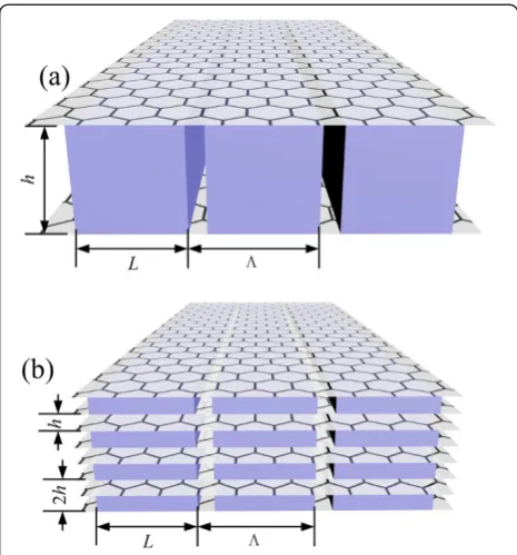
Figure 2Binary grating graphene structures. (a)The bilayer graphene structure.(b)The multilayer graphene structure.his the grating layer thickness.Λis the period of grating.L1is the width of
dielectric withε1.L(L2) is the width of dielectric withε2. The duty ratio
[image:2.595.304.541.519.694.2]isf2=L/Λ, andf1= 1−f2. In this paper, we simply setε1= 1 andε2= 4.
Rigorous coupled wave analysis in graphene-containing structures
In Figure 2a, we usedhto be the depth of grating (thick-ness of gratings). Thehwas also the distance between two graphene layers. In multilayer structures of Figure 2b, 2h was the longitudinal period. The structures were designed to only contain two kinds of interfaces.
In common, the conventional RCWA based on the Floquet's theorem [26] was unable to be used for the graphene-containing structures as the electric field will induce a current with current density J=σE, while gra-phene was included.
In RCWA, the field was expanded into the form of
Ex¼
X
n
Exð Þn eiðβnx−ωtÞ; Hy¼
X
n
Hyð Þn eiðβnx−ωtÞ:
ð6Þ
So the current density J can also be expended to the
sum of spatial harmonics with different wave vector components. To obtain the reflection, transmission, ab-sorption, field distribution, and other optical properties of such structures as shown in Figure 2, a nonzero item
must be included in the boundary condition of Hyfield
considering the induced current,
Hyþ−Hy−¼σEz: ð7Þ
According to the principle of superposition, Hy will
also be continuous at the interface if each spatial har-monics subcomponent satisfied the boundary conditions independently,
Hy n;x;y0þz
−Hyðn;x;y0−zÞ ¼σEzðn;x;y0zÞ; ð8Þ in whichnwas the order, ± in subscripts represented ap-proaching to y0from two different directions. After the modification on the RCWA program, we can utilize it to deal with the graphene-containing structures.
Results and discussion Phase matching condition
For a structure with a binary grating bounded by gra-phene layers on two sides shown in Figure 2a, the atten-uated total reflection spectrum is plotted in Figure 3 using the modified RCWA method when it was illumi-nated normally. A set of absorption peaks each corre-sponding to a GSP mode was shown in blue solid line. From left to right, each peak corresponding to a GSP
mode ordered with 1, 2…
[image:3.595.304.540.87.279.2]In the structure shown in Figure 2a, there exist two kinds of interfaces, i.e.,ε1-graphene-ε1andε1-graphene-ε2. When GSP is propagating along the interfaces, the phase shifts were φ1 and φ2 for the two kinds of interfaces,
Table 1 The resonant frequency of different orders
Order of GSP (N) 1 2 3 4 5 6 7 …
ω0(meV) (RCWA) 11.9 16.7 20.5 23.7 26.3 28.9 31.1 … ω1(meV)
(theoretical)
11.70 16.61 20.38 23.55 26.34 28.86 31.18 …
ω0was the numerical results obtained by RCWA.ω1was the theoretical results
from Equation10.
[image:3.595.57.291.96.149.2]Figure 5Absorption spectra for duty ratio vs the frequency fixing the light path of grating period.
[image:3.595.65.538.585.705.2]respectively. δ was the total phase loss considering two abrupt phase changes when GSP propagates across the joints between the two kinds of interfaces in a grating period. At the excitation frequency, the phase change in a grating period should satisfy the relation
φ1þφ2þδ¼2πN: ð9Þ
which was known to be the phase matching conditions
[27,28]. In Equation 9, N is the integer and can be
rewritten as
Nð Þ ¼ω k1
Λ β1ð Þω f1þβ2ð Þω f2þ δ Λ
; ð10Þ
wheref2=L/Λandf1= 1−f2,β1andβ2were the wave vec-tors of GSP on two kinds of interfaces, respectively. When
Nwas a nonnegative integer, the GSP mode could be
ex-cited, andNcan be defined as the order of surface modes. The resonant frequencies can be obtained both from
ab-sorption spectrum in Figure 3 and theoretically from
Equation10(δ= 0). They were given in Table1and agreed well for high order modes. But for low order modes, some deviations existed between numerical and theoretical caused by the coupling of GSPs on two graphene layers.
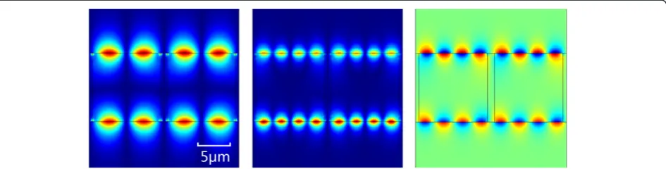
The field distributions of orders 1 and 2 of the struc-ture in Figure 2a were given in Figure 4. It was indicated that the GSP field distributions had nodes as standing wave because the GSP modes propagating in two direc-tions were excited simultaneously.
Duty ratio and stand wave interference
By using the modified RCWA, the absorption spectrum was obtained in Figure 5 when varying f, where f=φ1/ (φ1+φ2),φ1, φ2 had the same meaning as Equation 9. From the discussion above, when the phase match con-ditions were satisfied, GSPs could be coupled and ab-sorption peaks should appear. But some break points appeared as shown in Figure 5, which meant that GSPs cannot be excited at this frequency and this duty ratio and it was reasonable to believe that there must be other process related tofof controlling the excitation of GSP.
From the field distributions in Figure 4, each corner of the grating was a singular point of field and these scatting points became the sources of surface wave, as Figure 6 shown. In periodic, we only need to consider the scatting
in one period, i.e., A and B. Each scatting point will couple to two GSP modes propagating in two directions. So, the field can be expressed in four terms, which is [28,29]
F¼F0ei kð0x−ωtÞþF0eið−k0x−ωtÞþF0ei k½0ðx−x0Þ−ωtþπ
þF0ei½−k0ðx−x0Þ−ωtþπ
¼4F0sin k0x−k0x0 2
sink0x0
2 e
−iωt:
ð11Þ
First two terms were GSP excited by one set of points (A in Figure 6) with two propagating directions (blue and green) and the last two terms were that from
another set of points (B in Figure 6), where x0 is the
distance of A and B in the form of light path (k0x0=
L1β1=φ1= (φ1 +φ2)f= 2πNf). Because in real space, dif-ferent interfaces (ε1/ε1and ε1/ε2) had different propagat-ing constants, the expression might be complex. Here,
the light path of x was used. It is found that scatting
points A and B had a phase difference of π. This was
caused by the different geometric symmetries. From Equation 11, when sin(k0x0/2) = 0, i.e.,f = m/N(m= 0, 1,…,
N), field amplitude F would always be 0, which meant
[image:4.595.59.537.91.140.2]that the field cannot be excited. It was a cancelation process of two sets of standing waves that are coherent. Figure 6Corners of grating will become the scatting points of the incident light which was the source of GSPs.These scatting points can be divided into two kinds due to the geometric symmetry, which is A and B. Each scatting point will scatter into two GSP modes propagating in two directions (blue and green).
[image:4.595.305.540.532.713.2]So, for GSP mode ofN,N+ 1 of none absorption points appeared.
Coupling of GSPs on different graphene layers and resonant frequency shift
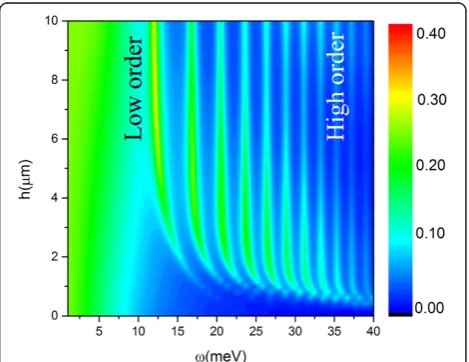
From Table 1, we can see that for higher order modes, the consistency between the theory and the numerical results from RCWA was better than that of the lower order modes. It was because the structure consists of bilayer of graphene and there could be interaction between GSP modes on neighbor graphene layers determined by the depth of the grating. In order to understand the behavior of GSPs coupling, in Figure 7, the absorption spectra
were given as a function of the grating deepness h. A
blueshift of absorption peaks was found when the grat-ing became thin. The oscillator model is used to de-scribe this phenomenon of spectrum blueshift [30,31].
€
xupperþγxupper_ ¼F0e−iðωt−φnÞ−ω20xupper−κðn;h;ΔθÞxlower
ð12Þ
In Equation 12, κ(n, h, Δθ) was the coupling coeffi-cient and n, h, and Δθ were order of GSP mode, thick-ness of grating, and phase difference of GSPs on two graphene layers, respectively. Essentially, the GSPs were surface waves so they interact with each other via evan-escent interactions, and the coupling intensity decayed exponentially with h increasing. For fixed h, the lower order modes had larger skin depth (stronger coupling in-tensity) than the higher orders; then, the stronger coupling resulted in a large spectra shift. The phase difference of Δθalso had affection to the absorption frequencies. How-ever, in our case, the wavelength (15 meV ~ 82.8μm) was
much larger than the thickness of grating layer (h=
10μm), it is reasonable to assumeΔθis approximately 0. This can also be obtained clearly from the field distribu-tion in Figure 4 that the electric fields on upper and lower graphene layers oscillated synchronously. This conclusion can still hold in multilayer graphene-grating structures. Finally, κ(n, h, Δθ) ∝ e−hq(n), where
q nð Þ ¼ β2ð Þn−ε 1;2k20
1=2
.
Suppose the solution of having the form ofxup=xdown=
x0e−iωt (no phase difference between GSP on neighbor layers), it is found that the resonant frequency became
ω2¼ω2
0þκðh;n;ΔθÞ−
γ2
2 : ð13Þ
Whenhwas small (h< 4μm), the largerκ(n,h,Δθ)∝e−h was the larger shift of resonant frequency would be. And obviously, κ(n, h, Δθ) was approaching 0 rapidly
when hwas large enough, which meant that the
reson-ant frequency became a stable value of ω2
0−γ2=2
1=2
. Otherwise, κ(n, h, Δθ) was also related to the order of GSP. The high order mode had a small skin deep with
weak coupling intensity and less blueshift. When h
[image:5.595.56.290.89.238.2]tends to be 0, the grating became too thin to excite the surface mode. This was why the absorption disappeared whenh= 0 in Figure 7.
Figure 8The absorption spectrums of grating-graphene periodic multilayer structure.‘Layers’, number of graphene layers, which is the odd number between 2 and 26. The frequency ranges from 0 to 60 meV (approximately 14.5 THz). The figure inset is the reflections.
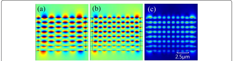
Figure 9Field distributions.The real part(a)and(b)and magnitude(c)ofEyin multilayer structure of different orders.(a)Excitation at the
[image:5.595.54.541.576.705.2]Strong absorption in grating-graphene multilayers Moreover, the behavior of multilayer structures shown in Figure 2b was also investigated using the modified RCWA and the absorption and reflection spectra were given in Figure 8. When increasing the number of gra-phene layers, it can be seen that the resonant frequen-cies do not change but for several lower order modes. Though the reflections were always weak within the res-onant range, it is obvious that the more graphene layers included, the stronger the absorption is (almost 90% when it contained 26 graphene layers).
The field distributions of Figure 9 also give the same conclusion that the stand waves on each graphene layer were almost oscillated synchronously. The energy was mainly located and absorbed by the graphene layer as we expected.
Conclusions
On conclusion, the rigorous coupled wave analysis was modified to compute the excitation of graphene surface plasmon in graphene-containing binary gratings struc-tures. Under the phase matching conditions, the excita-tion of the graphene surface plasmonics was determined by the distance between graphene layers and duty ratio of gratings, and the mode suppression can be realized by modifying the grating constant and duty ratio. A blue-shift of the excitation frequency was obtained for en-hanced coupling between GSP of neighbor graphene layers. Increasing the number of graphene layers had almost no effect on the excitation frequency of GSP but would lead to a high absorption with negligible reflec-tion in near-THz range. Finally, the resonant frequency and absorptions can be easily modified by manipulating the structure parameter, including grating constant, duty ratio, and distance between the graphene layers and number of grating, and graphene-containing grating might become potential applications of THz region, such as optical absorption devices, optical nonlinear, optical enhancement, and so on.
Competing interests
The authors declare that they have no competing interests.
Authors' contributions
HYU, XJ, and XS conceived the idea. HYU, PL, HYA, and XS wrote the codes, calculated the results, and made the conclusions. HYU, XS, and PL contributed to the preparation and revision of the manuscript. All the authors read and approved the final manuscript.
Acknowledgements
This project was supported by the National Basic Research Program of China (no. 2013CB328702) and by the National Natural Science Foundation of China (no. 11374074).
Received: 13 December 2013 Accepted: 28 January 2014 Published: 21 February 2014
References
1. Geim AK, Novoselov KS:The rise of graphene.Nat Mater2007,6:183–191.
2. Grigorenko A, Polini M, Novoselov K:Graphene plasmonics.Nat Photonics 2012,6:749–758.
3. Bonaccorso F, Sun Z, Hasan T, Ferrari A:Graphene photonics and optoelectronics.Nat Photonics2010,4:611–622.
4. Novoselov K, Geim AK, Morozov S, Jiang D, Grigorieva MKI, Dubonos S, Firsov A:Two-dimensional gas of massless Dirac fermions in graphene.
Nature2005,438:197–200.
5. Ju L, Geng B, Horng J, Girit C, Martin M, Hao Z, Bechtel HA, Liang X, Zettl A, Shen YR:Graphene plasmonics for tunable terahertz metamaterials.Nat Nanotechnol2011,6:630–634.
6. Koshino M, Ando T:Magneto-optical properties of multilayer graphene.
Phys Rev B2008,77:115313.
7. Gusynin V, Sharapov S, Carbotte J:Magneto-optical conductivity in graphene.J Phys Condens Matter2007,19:026222.
8. Dressel M:Electrodynamics of Solids: Optical Properties of Electrons in Matter. Cambridge: Cambridge University Press; 2002.
9. Falkovsky L, Pershoguba S:Optical far-infrared properties of a graphene monolayer and multilayer.Phys Rev B2007,76:153410.
10. Mikhailov SA, Ziegler K:New electromagnetic mode in graphene.Phys Rev Lett2007,99:016803.
11. Stern F:Polarizability of a two-dimensional electron gas.Phys Rev Lett 1967,18:546–548.
12. Jablan M, Buljan H, SoljačićM:Plasmonics in graphene at infrared frequencies.Phys Rev B2009,80:245435.
13. Nikitin AY, Guinea F, Garcia-Vidal FJ, Martin-Moreno L:Surface plasmon enhanced absorption and suppressed transmission in periodic arrays of graphene ribbons.Phys Rev B2012,85:081405.
14. Nayyeri V, Soleimani M, Ramahi OM:Modeling graphene in the finite-difference time-domain method using a surface boundary condition.InIEEE Transactions on Antennas and Propagation.Edited by. Piscataway: IEEE; 2013. 15. Peres N, Bludov YV, Ferreira A, Vasilevskiy MI:Exact solution for square-wave
grating covered with graphene: surface plasmon-polaritons in the THz range.J. Phys. Condens. Matter,25:125303. arXiv preprint arXiv:12116358 2012. 16. Moharam M, Grann EB, Pommet DA, Gaylord T:Formulation for stable and
efficient implementation of the rigorous coupled-wave analysis of binary gratings.JOSA A1995,12:1068–1076.
17. Moharam M, Pommet DA, Grann EB, Gaylord T:Stable implementation of the rigorous coupled-wave analysis for surface-relief gratings: enhanced transmittance matrix approach.JOSA A1995,12:1077–1086.
18. Neto AC, Guinea F, Peres N, Novoselov KS, Geim AK:The electronic properties of graphene.Rev Mod Phys2009,81:109.
19. Ziegler K:Robust transport properties in graphene.Phys Rev Lett2006,
97:266802.
20. Gusynin V, Sharapov S, Carbotte J:Unusual microwave response of Dirac quasiparticles in graphene.Phys Rev Lett2006,96:256802.
21. Falkovsky L, Varlamov A:Space-time dispersion of graphene conductivity.
Eur Phys J B2007,56:281–284.
22. Falkovsky L:Optical properties of graphene.Phys. Conf. Ser2008,129(1):012004. 23. Hanson GW:Quasi-transverse electromagnetic modes supported by a
graphene parallel-plate waveguide.J Appl Phys2008,104(8):084314–084314-5. 24. Mikhailov S, Ziegler K:A new electromagnetic mode in graphene.Phys.
Rev. Lett.2007,99:016803.
25. Economou EN:Surface plasmons in thin films.Phys Rev1969,182:539. 26. Petit R:Electromagnetic Theory of Gratings.Heidelberg: Springer Berlin; 1980. 27. Liu H, Lalanne P:Microscopic theory of the extraordinary optical
transmission.Nature2008,452:728–731.
28. van Beijnum F, Rétif C, Smiet CB, Liu H, Lalanne P, van Exter MP: Quasi-cylindrical wave contribution in experiments on extraordinary optical transmission.Nature2012,492:411–414.
29. Lalanne P, Hugonin J, Rodier J:Theory of surface plasmon generation at nanoslit apertures.Phys Rev Lett2005,95:263902.
30. Liu N, Langguth L, Weiss T, Kästel J, Fleischhauer M, Pfau T, Giessen H:
Plasmonic analogue of electromagnetically induced transparency at the Drude damping limit.Nat Mater2009,8:758–762.
31. Haus HA:Waves and Fields in Optoelectronics.Englewood Cliffs, NJ: Prentice-Hall; 1984.
doi:10.1186/1556-276X-9-90