An Array Partitioning Scheme of Airborne Phased-MIMO Radar
Based on STAP SINR
Wei Wang1, 2, *, Lin Zou1, and Xuegang Wang1
Abstract—An airborne phased-multiple-input-multiple-output (Phased-MIMO) radar with collocated antenna array is a tradeoff of phased array radar and MIMO radar. Its transmitting array is divided into multiple subarrays that are allowed to be overlapped. In this letter, we mainly study the array partitioning scheme of the airborne Phased-MIMO radar with equal uniform linear subarrays that are fully overlapped on the basis of space-time adaptive processing (STAP). A mathematical formula is derived to determine the number of subarrays and the elements in each subarray according to the principle of maximum STAP signal-to-interference-plus-noise ratio (SINR). The SINR performances corresponding to different partitioning schemes are simulated and discussed to demonstrate the effectiveness of the proposed mathematical formula for array partitioning in the sense of maximum STAP SINR.
1. INTRODUCTION
PHASED-MIMO radar is a novel system that combines the coherent processing gain of phased array radar with the waveform diversity advantage of MIMO radar [1]. The transmitting array of Phased-MIMO radar is divided into a number of subarrays. Each subarray is employed to coherently transmit an individual waveform. Those waveforms are set to be orthogonal with one another. Hence, those subarrays are mutually combined to be a MIMO system while the coherent processing gain can still be obtained by designing the beamforming weights of each subarray [1].
Space-time adaptive processing (STAP), a two-dimensional space-time adaptive filtering operation, is an effective and important technique that is widely used in airborne radar for clutter suppression and moving target detection in the strong clutter environment [2–4]. Since the Phased-MIMO radar is able to provide a tradeoff between the benefits of phased array radar and the advantages of MIMO radar [1], how to apply those traditional STAP methods to airborne Phased-MIMO radar for performance improvement of clutter suppression is valuable to be studied. An orthogonal projection technique on the clutter subspace and a deterministic direct data domain approach for the STAP of airborne Phased-MIMO radar in the nonhomogeneous clutter scenario are presented in [5]. An estimation rule for clutter degrees of freedom (DOFs) is proposed in [6] for further investigation of the STAP on airborne Phased-MIMO radar. Moreover, in [7], four typical classes of reduced-dimension STAP algorithms are extended to airborne Phased-MIMO radar, and the corresponding rules of clutter rank estimation are also presented. On account of the definition of Phased-MIMO radar, it is clear that one of the key points is how to divide the transmitting array into multiple subarrays. Through MATLAB program, the signal-to-interference-plus-noise ratio (SINR) performances of the spatial beamforming for the Phased-MIMO radar are analyzed in the situation of fully overlapped subarrays in [8]. Another partitioning scheme that is also allowed to be overlapped is proposed in [9] to improve the main-to-sidelobe levels and
Received 15 August 2018, Accepted 2 October 2018, Scheduled 22 October 2018 * Corresponding author: Wei Wang ([email protected]).
1 School of Information and Communication Engineering, University of Electronic Science and Technology of China, Chengdu 611731,
signal-to-noise ratio (SNR) without the reduction of beampattern directivity. The main concept of this new scheme is to place the transmitting beampattern nulls at the peak sidelobes of the waveform diversity beampattern and place the waveform diversity beampattern nulls at the peak sidelobes of the transmitting beampattern [9]. Additionally, a Phased-MIMO radar with unequal overlapped subarrays is proposed in [10]. The unequal size and greater length of the subarrays can not only provide the improvements of transmitting and receiving beampatterns but also enhance the output SINR of spatial beamforming.
Note that those partitioning schemes aforementioned are all discussed according to the performances of the spatial beamforming. However, we consider that the array partitioning scheme will also influence the STAP performance of airborne Phased-MIMO radar. Then, we further study the array partitioning scheme of the airborne phase-MIMO radar with collocated antenna array in the case of equal uniform linear subarrays that are fully overlapped in this letter. A mathematical formula is derived to determine the number of subarrays and the elements in each subarray according to the principle of maximum STAP SINR.
The paper is organized as follows. Section 2 is devoted to the STAP model of airborne Phased-MIMO radar with equal uniform linear subarrays that are fully overlapped. The mathematical formula for array partitioning scheme in the sense of maximum STAP SINR is derived in Section 3. In Section 4, simulations and discussions are given to demonstrate the effectiveness of the proposed mathematical formula. Conclusions are finally presented in Section 5.
2. STAP MODEL OF AIRBORNE PHASED-MIMO RADAR
Consider a side-looking airborne Phased-MIMO radar with collocated transmitting and receiving uniform linear arrays (ULAs), which consist ofN receiving antenna elements with spacingdR=λ/2 and
M transmitting antenna elements with spacing dT =γdR, where λ is the wavelength andγ =dT/dR is the sparse coefficient. The transmitting array is divided into K(1 ≤ K ≤ M) equal uniform linear subarrays that are fully overlapped. Then, each subarray is composed of MK = M −K + 1 omnidirectional antenna elements. It is assumed that the beams of all the transmitting subarrays have the same direction. The velocity of the radar platform isv. In addition, there are P pulses with pulse repetition interval (PRI) T in a coherent processing interval (CPI) for each range gate. Note that
M, N, K, P ∈N+, whereN+ denotes the set of positive integer.
Firstly, the receiving spatial steering vectorvR(fs) and temporal (Doppler) steering vector vD(fd) for the airborne Phased-MIMO radar are given as follows
vR(fs) =
1, ej2πfs, . . . , ej2π(N−1)fs T
(1)
vD(fd) =
1, ej2πfd, . . . , ej2π(P−1)fd T
(2)
where [·]T denotes the transpose operation, and fs and fd denote the spatial frequency and the normalized Doppler frequency, respectively. Supposing no antenna crabbing, they are given by
fs = dRcosθ/λ (3)
fd = 2vTcosθ/λ=βfs (4)
where θ indicates the angle-of-arrival (AOA) of the source and β = 2vT /dR. Moreover, different from phased array radar and MIMO radar, the transmitting spatial steering vector of the airborne Phased-MIMO radar vT(fs) is given by [1]
vT(fs) =b(fs)d(fs) (5)
where stands for Hadamard product, andb(fs) and d(fs) can be given by
b(fs) =
wH1 a1(fs), . . . ,wHKaK(fs)
T
, (6)
d(fs) =
e−jδ1(fs), . . . , e−jδK(fs)T (7)
where [·]H denotes the conjugate transpose operation;w
respectively. δk(fs) is a phase term that indicates the time required for the wave to travel across the spatial displacement between the first antenna of the transmit array and the first antenna of the kth subarray [1]. Finally, the space-time steering vector of the airborne Phased-MIMO radar can be given by
v=vD(fd)⊗vT(fs)⊗vR(fs) (8)
where ⊗ denotes the Kronecker product. For the equal uniform linear subarrays that are fully overlapped, we have
a1(fs) =. . .=aK(fs) =
1, ej2πγfs, . . . , ej2πγ(MK−1)fs T
. (9)
And we only consider non-adaptive beamforming for subarray here due to the space limitation. So the weight vectors of those subarrays are set as
w1=. . .=wK =aK(fs). (10)
Then,b(fs) can be particularly rewritten as
b(fs) =aHK(fs)aK(fs)[1, . . . ,1]T =MK[1, . . . ,1]T. (11)
We assume thatNcclutter patches are uniformly distributed in each iso-range ring and independent with one another. The spatial frequency and the normalized Doppler frequency of theith clutter patch are denoted as fs,i and fd,i, respectively. Ignoring the range ambiguities, the clutter echo c can be modeled as the summation of these independent clutter patches, which can be expressed as
c= Nc
i=1
σc,ivD(fd,i)⊗vT(fs,i)⊗vR(fs,i) = Nc
i=1
σc,ivc,i (12)
where σc,i and vc,i denote the complex amplitude and the space-time steering vector of theith clutter patch, respectively. The clutter covariance matrix (CCM)Rc can be given as [2]
Rc = Nc
i=1
σc,i2 vc,ivHc,i (13)
whereσ2c,iis the power of theith clutter patch. The noise covariance matrixRn can be described as
Rn=σ2nIN KP (14)
whereσ2n is the noise power, andIN KP is an identity matrix with size of N KP ×N KP.
In addition, supposing that the spatial frequency and normalized Doppler frequency of the target arefs,t and fd,t, respectively, the target signal can be written by
s=σtvD(fd,t)⊗vT(fs,t)⊗vR(fs,t) =σtvt (15)
where σt and vt denote the complex amplitude and space-time steering vector of target, respectively. Then, the output SINR can be expressed as
SINR = w Hs2
wHRuw (16)
where w is the N KP ×1 weight vector for STAP filter, and Ru = Rc+Rn is the clutter plus noise covariance.
3. DERIVATION OF PARTITIONING SCHEME
Note that when w = κR−u1s where κ is an arbitrary scalar that does not alter the output SINR, expression (16) can achieve its optimum that is denoted as SINRopt and given by [4]
Furthermore, according to the perspective of SINR-loss in the STAP application, SINR in the background of clutter plus noise is less than or equal to the one in the background of only noise [4]. Then, we can see that
SINRopt-n=sHR−n1s=
sHs σ2 n = σ 2 t σ2 n
N KP MK2 = σ
2
t
σ2
n
N KP(M −K+ 1)2≥SINRopt (18)
where SINRopt-n denotes the optimum SINR in the background of only noise. It is clear that expression (18) has a closed form with respect to the parameter K (i.e., the number of subarrays). Thus, it is possible to find an optimum value ofK that is able to make SINRopt-n achieve its maximum. That is to say, it is possible to find a deterministic partitioning scheme to achieve the maximum STAP SINR based on Eq. (18), which can be seen as an optimization problem as follows
max f(K) =N KP(M−K+ 1)2
s.t. K ∈N+, 1≤K≤M . (19)
In order to solve this optimization problem, we first define a continuous differentiable function f(K), which is given by
f(K) =N KP(M −K+ 1)2
K∈R+, 1≤K ≤M (20)
where R+ denotes the set of positive real number. Then, we can find the extreme points off(K) by
solving the equation
df(K)
dK =N P(M+ 1−3K
)(M+ 1−K) = 0 (21)
where dfdK(K) means taking the derivative of f(K) with respect toK. Obviously, the two solutions of Equation (21) are K1 = (M + 1)/3 andK2 =M + 1. But in view of the constraint in Equation (20),
the solution K2 > M should be discarded since it does not fall into the definition domain of K. In
contrast, the solutionK1 would be located in the definition domain of K as long as M >1. Moreover,
we can see that the second-order derivative of f(K) with respect to K is existent. We can further obtain the value of the second-order derivative at point K1, which is given by
d2f(K)
dK2
K=K1
=−2N P(M+ 1)<0. (22)
Based on Eq. (22), it is shown that the value of the second-order derivative at pointK1 is less than zero,
which illustrates that K1 is a local maximum point of f(K) in the continuous domain 1 < K < M.
Furthermore, it is noted that
f(K =K1)≥f(K = 1)> f(K =M) (23)
whenM >1. We can see that the function value atK1 is larger than or equal to the function values at
the boundary points of the definition domain. Hence, K1 can be seen as the global maximum point of f(K) in the whole domain 1 ≤K ≤M when M >1. Furthermore, when M = 1, K = 1 is actually the only point off(K), which is still reasonable to be seen as the global maximum point.
Note thatf(K) has the same formulation withf(K) except for the different definition domains of function variables. Hence, we can derive the global maximum point of f(K) through rounding K1 to
the nearest integer, since K1 may be a decimal number that is not included in the definition domain
of K. In other words, the optimum number of subarrays corresponding to the maximum SINR can be computed by
Kmax= round(K1) = round
M + 1
3 (24)
where round(·) denotes the rounding operation. In summary, for achieving a maximum STAP SINR, an effective array partitioning scheme of the airborne Phased-MIMO radar with collocated ULA is to divide the transmitting array intoKmax fully overlapped subarrays, each withM−Kmax+ 1 elements.
4. SIMULATIONS
In the simulations, we setγ = 1,λ= 0.23 m, v= 140 m/sT = 0.41 ms, thenβ = 1. There are Nc = 180 clutter patches uniformly distributed in the forward area of the antenna array. The noise power is normalized to 0 dB, and the clutter-to-noise ratio (CNR) is 30 dB. The spatial frequency, normalized Doppler frequency and power of target are supposed to befs,t= 0,fd,t=−0.25 and 10 dB, respectively. The number of pulses in a CPI is P = 8.
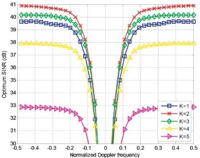
The optimum SINR performances versus the normalized Doppler frequencies for different numbers of subarrays withM =N = 5,M =N = 6 andM =N = 7, which are computed according to Eq. (17), are shown in Fig. 1, Fig. 2 and Fig. 3, respectively. From Fig. 1, we can observe that the best SINR performance is obtained atK = 2. Meanwhile, we can see that Kmax=K1 = 2 whenM = 5 according
to Eq. (24), which is coincident with the results in Fig. 1. Moreover, the highest SINR level in Fig. 2 is also reached at K = 2 while K1 = 2.33 and Kmax = 2 when M = 6. Note that the highest SINR
in Fig. 2 is just slightly higher than that at K = 3 while the best SINR in Fig. 1 is obviously larger than the others. It is because Kmax = 2 is not the true solution of Eq. (21) when M = 6 but just a
rounding approximation that is more close to the optimum value of K1 = 2.33 than K = 3. At last,
in Fig. 3, the partitioning scheme for maximum SINR is changed to K = 3 in the condition of M = 7 while K1 = 2.67 andKmax = 3, sinceK = 3 is more adjacent to K1 thanK = 2. The results in Fig. 3
are still identical with formula (24).
Figure 1. Optimum SINR performances versus the normalized Doppler frequencies for different numbers of subarrays with M =N = 5.
Figure 2. Optimum SINR performances versus the normalized Doppler frequencies for different numbers of subarrays with M =N = 6.
In addition, seen from Fig. 1 to Fig. 3, the worst SINR performances always appear atK=M. It is because Phased-MIMO radar would be transformed into MIMO radar when K=M, and the coherent gain of phased array radar is completely lost. Furthermore, though Phased-MIMO radar would be transformed into phased array radar and the coherent gain would reach the maximum at K = 1, the SINR levels do not reach the maximums in this case, as shown in these figures. It is because phased array radar is unable to combine the transmitting and receiving arrays into a larger virtual array for SINR improvement due to the lack of waveform diversity property of MIMO radar. Therefore, the Phased-MIMO radar with the proposed partitioning scheme can provide a significant tradeoff between the coherent gain and the waveform diversity to maximize the STAP SINR performance.
Figure 3. Optimum SINR performances versus the normalized Doppler frequencies for different numbers of subarrays with M =N = 7.
Figure 4. Pd performances versus SCR for different numbers of subarrays withM =N = 5.
Figure 5. Pd performances versus SCR for different numbers of subarrays withM =N = 6.
Figure 6. Pd performances versus SCR for different numbers of subarrays withM =N = 7.
depicted in Fig. 1 to Fig. 3, the descending order and spaces for the Pd performance degradation associated with different values of K are also coincident with the descending order and spaces for the SINR performance degradation associated with different values of K.
5. CONCLUSION
to achieve a maximum STAP SINR. In the future, we could further study the partitioning scheme using adaptive beamforming for subarrays. Additionally, except for SINR, research on the relationships between some other STAP performances and the partitioning scheme of airborne Phased-MIMO radar might be an interesting work too.
REFERENCES
1. Hassanien, A. and S. A. Vorobyov, “Phased-MIMO radar: A tradeoff between phased-array and MIMO radars,”IEEE Trans. Signal Process., Vol. 58, No. 6, 3137–3151, Jun. 2010.
2. Melvin, W. L., “A stap overview,” IEEE Aerospace and Electronic Systems Magazine, Vol. 19, No. 1, 19–35, Jan. 2004.
3. Klemm, R., “Principles of space-time adaptive processing,” The Institution of Engineering and Technology, London, UK, 2006.
4. Guerci, J. R.,Space-time Adaptive Processing for Radar, Artech House, Boston, USA, 2003. 5. Ahmadi, M. and K. Mohamed-pour, “Space-time adaptive processing for
phased-multiple-input-multiple-output radar in the non-homogeneous clutter environment,” IET Radar, Sonar and Navigation, Vol. 8, No. 6, 585–596, Jun. 2014.
6. Xie, W., X. Zhang, Y. Wang, and Y. Zhu, “Estimation of clutter degrees of freedom for airborne multiple-input multiple-output-phased array radar,” IET Radar, Sonar and Navigation, Vol. 7, No. 6, 652–657, Jun. 2013.
7. Feng, W., Y. Zhang, and X. He, “Complexity reduction and clutter rank estimation for MIMO-phased STAP radar with subarrays at transmission,” Digital Signal Processing, Vol. 60, 296–306, 2017.
8. Ismail, N. E., S. H. Mahmoud, A. S. Hafez, and T. Reda, “A new phased MIMO radar partitioning schemes,”2014 IEEE Aerospace Conference, 1–7, Big Sky, MT, USA, 2014.
9. Alieldin, A., Y. Huang, and W. M. Saad, “Optimum partitioning of a Phased-MIMO radar array antenna,” IEEE Antennas and Wireless Propagation Letters, Vol. 16, 2287–2290, 2017.