'iFflllWf 8
I'!
*fmEUR
■M
m
THE EUROPEAN COMMUNITIES
\Ψϊ
m
liití
m
il
ΨΜ'
THE SLUGFLOW EQUATION
■ βι ή.il
«Γ
m
W
m
'""UW
Bfcfa
Ä
w
HttPM IJl
EP
Til''M
a«..«
} ? j j i
.■i«
» *■'¿».•d
irfjÄ
( ■ ' ■ " Ï
'iSSWIfS
M
1972
»hl, j*it*»:Mimi
Ö
'« '•«HfliMQl
»AH
M
ml
Joint Nuclear Research Centre
·<
;'W+
:,i,
j^^HRirP^i
■ ■»
h*•Tie*'
Ispra EstablishmentItaly
lf
fh„..»g
ytø
na
\â
''USUr
Wfcr %ãr
Jgl§ .til
S É ^ L NOTICE | J f
This document was prepared under the sponsorship of the Commission of the European Communities.
Neither the Commission of the European Communities, its contractors nor any person acting on their behalf:
iíawBSiÉLr
make any warranty or representation, express or implied, with respect to the accuracy, completeness, or usefulness of the information contained in this document, or that the use of any information, apparatus, method, or process disclosed in this document may not infringe privately owned
rights;or
MrP*
1
WBGSÊÈÊ/fi
assume any liability with respect to the use of, or for damages resulting from the use of any information, apparatus, method or process disclosed in this document.
il
#m
aÊ&Êâ
JBÊÊ
This report is on sale at the addresses listed on cover
I at the price of B.Fr. 40
When ordering, please quote the EUR num indicated on the cover of each report.
Siiwiwir
mSÈsSSm
EUR 4811 e
THE SLUGFLOW EQUATION by L. NOBEL Commission of the European Communities
Joint Nuclear Research Centre — Ispra Establishment (Italy) Technology
Luxembourg, May 1972 — 26 Pages — 6 Figures — B.Fr. 40.—
In the report is discussed the validity of the slugflow equation given, amongst others, by Nicklin et al. It appears that other types of equation are also possible probably due to the fact that the coefficient of the total volume flow rate taken by Nicklin et al. as a constant, in fact would be a function of bubble length and total volume flow rate.
EUR 4811 e
THE SLUGFLOW EQUATION by L. NOBEL Commission of the European Communities
Joint Nuclear Research Centre — Ispra Establishment (Italy) Technology
Luxembourg, May 1972 — 26 Pages — 6 Figures — B. Fr. 40.—
This conclusion is based on the assumption that the displaced liquid flowrate pro unit of bubble cross-section at the rear-end of the bubble, caused by the relative motion of the bubble is invariant with this cross-section and also with the total volume flow rate.
If this theory holds good the consequences are that the bubble diameter decreases with increasing total volume flow, for constant remaining bubble lengths.
This conclusion is based on the assumption that the displaced liquid flowrate pro unit of bubble cross-section at the rear-end of the bubble, caused by the relative motion of the bubble is invariant with this cross-section and also with the total volume flow rate.
EUR 4811
e
COMMISSION OF THE EUROPEAN COMMUNITIES
THE SLUGFLOW EQUATION
by
L.NOBEL
1972
Joint Nuclear Research Centre Ispra Establishment-Italy
ABSTRACT
In the report is discussed the validity of the slugflow equation given, amongst others, by Nicklin et al. It appears that other types of equation are also possible probably due to the fact that the coefficient of the total volume flow rate taken by Nicklin et al. as a constant, in fact would be a function of bubble length and total volume flow rate.
This conclusion is based on the assumption that the displaced liquid flowrate pro unit of bubble cross-section at the rear-end of the bubble, caused by the relative motion of the bubble is invariant with this cross-section and also with the total volume flow rate.
If this theory holds good the consequences are that the bubble diameter decreases with increasing total volume flow, for constant remaining bubble lengths.
KEYWORDS
3
-Contents
Summary
The slug flow equation 5
5
THE SLUG FLOW EQUATION *)
If a cocurrent twophase flow, in a vertical tube which
commonly has a diameter greater than 10 mm, is charac
terised by bullet or piston shaped gas bubbles (also called
G.I. Taylor b u b b l e s ) , separated from each other by liquid
slugs with a length of at least six tube diameters (a flow
pattern known as fully developed slug f l o w ) , the velocity
of the bubbles may be expressed according to NICKLIN,
WILKES and DAVIDSON ' by the equation:
VG = C1VM + C2 ^ ¿ ^ ( D
In this equation the meaning of the symbols is
V = bubble velocity (m/sec)
G
V = volume flow density or throughput velocity
M
of the gasliquid fluiu combination (m/sec)
% QT
( V = V + ν = — + = )
kVM GA LA A A ;
D = diameter of tube (m)
A = T T A . D2U2)
Q and o = volume flow of gas and liquid respectively
For an airwater system C = 0,35, as has been theoretically (2)
determined by DUMITRESCU , and experimentally confirmed
( 3 )
by NICOLITSA a n d MURGATR0YDv ' among o t h e r s . A s s u m i n g C t o b e
6
-invariant with Vw l Nicklin et al obtained for C. the
va-il 1 lue 1,2. In their experiments single bubbles were
injec-ted at the base of the test section with such low fre-quency that during the rise of the bubble V = 0 could be maintained. The liquid volume flow density V
(superficial liquid velocity) was varied between 0,3 m/sec and 2,5 m/sec. The same technique for injecting single bubbles was employed by Nicolitsa and Murgatroyd.
These research teams obtained a value of 1,24 for C in the
range for V between 0 - 0,25 m/sec, with a spread of - 2%. LA
Both series of experiments, i.e. those of Nicklin et al and those of Nicolitsa and Murgatroyd, were carried out in tubes of about one inch diameter and their results could be considered to be congruent.
(4)
However, GRACE et al , performing slug flow experiments in stationary water with a steady state air flow in a one inch tube, and with a superficial gas velocity of up to about 0,2 m/sec, arrived at the following slug flow equa-t ion :
V
G
= 1'
11 VGA + 0,359 V T ^
( 2 )So we have already three different values for C , i.e 1,24, 1,2 and 1,11.
Still more diversity is caused by the results of work
performed by MARRUCCI et al ( 5 ).
This team obtained, in five tubes of diameters 1,6: 2,1: 2,8: 4,2: and 5,3 cm respectively, and with an air-water system, results which can be described by the equation:
7
-E q u a t i o n s 2 and 3 c o u l d be w r i t t e n i n a more g e n e r a l f o r m ,
i . e . ,
V
G -
VM
+ C3
VO A
+ 0«
3 5V ~ r D
(4)and for C we already have two values, i.e. 0,11 and 0,17.
These results are supported by observations made by
VAN HEUVEN and B E E K( 6 .
Although no information on the water velocity has been pro
vided, we can translate their results into our type of for
mula and express them as
Vr. = ▼„ + 0,216 V
i/4
M GA (5)
The experiments were performed in tubes with diameters of
0,48 cm and 0,238 cm, at superficial gas velocities of be
tween 0,1 and 0,7 m/sec, and are in a certain sense beyond
our scope. Equation 5 could be written in the form of e
quation 4, but because
E = £.g.D = 3,13
is beneath the critical value of 4, according to WHITE and (7)
BEARDM0RE v , C = 0.
1/. In the same context, C = 0,216 V
o GA
and is thus no
longer a constant. It is true, in spite of all these diver
gencies, C = 1 and C ^ 0.
θ
-For small values of V only bubbly flow exists. Using a GA (8)
criterion of STEWART and DAVIDSON , that in stationary water slugging starts if
GA
VW
> 0,2we may write for the boundary line indicating initial slug-flow for the 0,48 cm tube, based on equation 5,
V - 1,076 VM
D (6)
If we now go over our findings, we may conclude that there is obviously no uniform, and perhaps not even a generally valid interpretation of the results.
If we plot the results of the group with V as a function of
o
V , V and V g D according to equation 4, then we ob tain the situation that has been illustrated in Fig. 1. In this Figure we have taken V as being constant. At a
cer-L A
tain value of V , bullet.shaped bubbles will be formed, and o A they will move at the velocity V .
Following equation 6, then C„ = 0,076.
For higher air velocities, we follow curve V - V and 1 2
C„ increases.
This curve may be approximated by the straight line A-B.
In Fig. 1 the mutual relationships between the functions are pronouncedly out of scale, so as better to express the mean ing of the approximations. In Fig. 2 a more realistic pre sentation has been given.
9
-The line 0* - C is the "lowest" slug flow line.
The line O'-V is here the upper slug flow line. The
G2
triangle between these lines represents all possible
slug-flow situations.
For this sector an average inclination may be given,
cor-responding to the constant 1,2 in the equation of
Nicklin et al.
Successively we obtain the following variations and
modi-fications of the slug flow equation:
1. For V = const, the slug flow equation may be written
LA
i n t h e f o r m :
VG : VM + C2 V S D + C3 VraGA
(extension of eq. 5)
2. This relation may be sufficiently approximated by the
relation
M
V
G= V
M +C
2V g D + C 3 V
G A(see eq. 4)
3. For different V - values, the equation may be
LA
written as:
V
G
= Cl
VM
+ C? V 8
D<
s e e ecl· D
here, C is a variable.
4. For a rougher indication C
1may be taken as the
10
-Assumptions 3 and 4 may be checked by comparison with ( 9)
the work of STREET and TEK . In this work the spread in C, lies between C, » 1,1 and C,1 1 1 *a 1,4.
Before continuing, we should perhaps discuss the accuracy of the Nicklin equation.
In this connection we can say that a bullet-shaped bubble acts on the liquid flowing ahead of it as a displacement device, due to the difference in velocity between bubble and liquid. The flowrate of this displaced liquid may be found to apply the continuity equation over the rear-end cross-section of the bubble. If we express the void frac tion there by the symbol ζ , the "displacement" liquid flowrate V = V (1 - £c) follows from the equation
LDA LD (see Fig. 3 ) :
Vp ξ _ VT_ (1 - ξ ) = V (7)
G c LD c M
and, solving for V , we obtain: G
VG « XU VM + '/ζ VLDA (8)
c c V
The expression LDA represents the specific "displaced
liquid" flowrate due to the displacement action of the bubble. Now it can be imagined that this specific "displaced liquid" flowrate should be invariant with the rear-end cross-section of the bubble for a given tube diameter. Let us postulate that this would be the case.
The solution of equation 8 for V„ = 0 gives M
^ = C
2 V/ £ T (9)
11
Assuming that this solution is invariant for V also,
we obtain as the first equation
V
G
= 1 / ξο
VM
+°2\/^
(10)If our postulation is valid, comparison of equations 1 and
10 leads to
C 1 ( 1 1 )
Thus C. = 1,2 corresponds to
viously the average value of ξ
0,833, which is ob·
Nicklin et al explained the coefficient 1,2 by the maximum
value of the liquid velocity at the center line in relation
to the average liquid velocity equal to V .
For laminar flowing liquids, the velocity at the center line
is equal to 2 Vw.
M
This was the explanation of GRACE et al for their experi
mental findings with an airsugar solution system.
They obtained: C = 2,12 and C = 0,194.
C was in very close agreement with the correlation pre
sented by White and Beardmore and C was very close to the
factor 2.
However, COX has shown that for viscous liquids the
fractional amount of liquid left in the tube when a "bubble"
UT U
has expelled the other fraction, is a function of *■*
12
-For high values of ^LU , ξ tends to the asymptotical
c . 1
value of 0,4, hence the assumption ξ = — - — — = 0,471, as would follow from the worK of Grace et al., could be supported by the work of Cox.
The results of GOLDSMITH and M A S 0 N( 1 1 ) also show that
for a tube of diameter 0,8 cm, a film thickness of 1,08 mm will be obtained for an air-oil system with μ = 8,41 P. This corresponds to a ξ -value of 0,533.
(12) . .
From the work of K0UREMEN0S , a similar conclusion, though approximative in numerical value, may be drawn.
According to this work, the manometrical pressure height produced by a bubble is to be expressed by the relation
bm A s
h is the friction pressure height
V, is the volume of a bubble. b
Now we can write roughly £
ξοΑ
Assuming further that particularly for the longer bubbles h, *v» £, we obtain: bm '
h =s c I (1- ξ ) .
For a tube diameter of 4,5 cm, according to the relation given by Kouremenos,
l ì
bere μτ i s the v i s c o s i t y of any fluid other than water,
L
ut, i s the v i s c o s i t y of water.
W
With our approximations we obtain:
Ì 1 Ì £ 0,115 ( ^ ) ° ·2 2 2 + 0,0588 A 0 » 1 1 5
ξο VW WW
(13)
For y= 8,41 Ρ as in the case of (10), we obtain ξ = 0,60.
A calculation method is given for the liquid flow between
bubble and wall in (1).
For V = 0, the flow balance gives
(1 Ç
c)(/2gT
0 , 3 5 / 7 D T=ξ
c.
0,35
\fW
(14)This equation is to be considered valid for any cross
section of the bubble, if we imagine that any bubble is a
part of an ideal bubble. It now yields for the liquid hold
up around the bubble:
fA
£ = 1 | (lξ) ai = 0,495 (15)
This solution holds to — ^5 (see ( 1 ) , fig. 2 ) . To "fit" the
holdup curve for — >5, we write equation 14 as follows:
(1 ξ) C^y 2 g U + A ) 0,35/"gT = ξ0,35^/^0" (16)
In t h i s formula, for % - 0, and i= 0,
C£ / 2 g T = 0 , 3 5 / g T
14
-£ = 0,0612 D
Ρ (17)
being equal to h, - £
° ^ bm
The factor C is an adaptation factor, and from (16) follows :
0,35
1-ξ
ι / — 2 —
V
2(£+£ )
(18)
From this equation follows for £ <<£ , following formula (15)
C = 0 495 áüESp.
L£ u,Has d ( x / D ) (19)
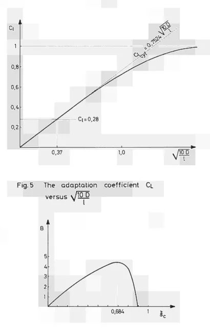
From fig. 2, ref. ( 1 ) , we derive our fig. 4; the relation between the liquid hold-up in multiples of tube diameter versus the square root of £/D. Graphic differentiation of this function finally gives the coefficient C, .
The coefficient C is plotted versus in fig. 5 .
£ F £
It may easily have been found by using equation ( 1 8 ) , in which, for a cylindrical bubble with a film thickness <S,
'cyl
^ 0,0198 D /lO D (20)
( 13 )
According to the work of STREET and TEK ζ and thus equation (18) becomes max
0,895
C = 0,7524 cyl /
10 D
(21)
For small values of
the bigger values of
10 D
10 D
equation 21 may be used. For
, i.e. for short bubbles, the real value of C is somewhat below C , as is demonstrated
15
For V > 0, equation (16) may be extended as follows:
(1ξ) C , / 2g( £+£p) ( VG VM> VM] = VGÇ VM (22)
in each crosssection of the bubble, equation (22) may be
applied. Now,
(V V )
v G M'
2g
For slugflow V.. = 2 m/sec, and for a tube of about
M max
2,5 3 cm, £ = 1 cm .
_E
Thus i n most c a s e s £ may be i g n o r e d . For ξ = ξ
Ρ c
e q u a t i o n ( 2 2 ) b e c o m e s :
( 1 ξ
ο)
Γθ
£νΛ2ΐΤ -
l/Ç
cV
M+
0 , 3 5 / I D J= ξ
α0 , 3 5 / Ι τ Γ
(23)
Writing now for
for slug flow:
NF R
Ν we obtain, as a general expression
r R
[ ι SJ2Í
' 0 Ρ IS η
C£ 2£ J c
1 ξ
• ξ. (24)
Also in this formula C is an adaptation coefficient equal
to:
0,35 J D ' NF R
c
i -
ι-ξ
ο\—
+ΤΓ
c c
(25)
Equation (25) may be compared with equation ( 1 8 ) . The latter
equation, with £ ignored, may be written as C and we ob
o tain, in general, writing for ξ at V = Ο,ξ
r i - Çc- i i - e .
C
£ =
C
£ L
1 +
Τ
oL c 'c
1 ± ^
J i-e
o16
-Here Β 0,3 5^g'De
Now the relation between ξ and ξ is unknown. There are o c
two possibilities for this relation, which are extremes of reality.
The first extreme is:
C„ = C. and the relation between ξ and ξ may be written £ £ o c J
o
ξ - ξ ?
t-^br-
irr '">
c o
If this relation is plotted for ξ = 0,895, we obtain at ξ =0,7 , Β = 4,30 , see fig. 6 . For a one-inch tube
o ' ' max ' '
this means V,. =0,75 m/sec. This is certainly too low. M
Another extreme is ξ = ξ c o This gives
1 - ζ(
C
£
=
C£
(1+o o"T"
Β) (28)The reality will probably lie between these two expressions,
and we may expect an expression, such as:
C£ (1+φΒ)
o (29)
In that case
Β =
ι-ξ.
(1-ξ ) - φξο c (30)
In equation (29), φ will be a variable; for low values of 10 D n Ί Ί„ , , 1-0.895 , _ . . .
— , φ ->0,117, because ψ= ■ *QC. , and for high values of — , φ-* 0, because C -> C
0,895
17
1ξ, It is thus clear that 0
However, φ is also a function of Β and for the moment
only fictitious models are available for study, due to
the lack of knowledge.
The extreme φ = 0, or C = C gives, for an increasing B,
X» X»
a decreasing ξα as follows from fig. 6. (The part left
from the max. for Β does not belong to the solution of
equation (27 ) ) .
This kind of tendency may generally be expected with more
realistic values for φ.
This can also be proved by means of equation ( 2 2 ) .
-Í2
Since C. = 1 and V V„ = \J2g £ , for short bubbles,
£ G Μ ρ ' '
1 ξ
V
JLL·£+£
Using the formula of Nicklin £ =
(0,2 VM + 0,35 y/g~D):
_
and for increasing V , £ is therefore increasing and ξ
accordingly decreasing.
Finally the following observations can be made.
Equation (21) suggests that for £>"», C = 0. It may be
imagined, however, that a limit value for £/D exists.
From wave theory we know
C
w» — =
V
2g h
or
C ^ 0,28
νΤΤϊς
18
-In this formula C„ = velocity of the wave over shallow
W J
water
h = wave length. W
In the case of slug flow, assuming the bubble is a wave, we obtain:
CW = VG + VLD
h
w
=*·
Thus :
W
=Τ"
VM
+°»
3 5V
rl^ + irf- 0,35VgD'
and applying equation (31), we obtainN FR
0,28
d - °.
|_
35
/ΣΤ 1
Χ
0,28(1-ζ )
V2£ J
(32)
Equations (24) and (32) are identical, if C = 0,28 . X»
Substituting the value C = 0,28 in equation (21). the result is £/D = 72 .
For this value, F(£) = 1 - £ x | | y _ i _ = 0,896 being the limit value for ξ .
c
No higher values can be found for £/D in the literature at present available.
19
-Conclusions
1. There is a strong indication that in the Formula of Nicklin et al^1^
VG = Cl + C2
C1 is not a constant value.
This follows from the work of other researchers ( M , (5),
( 6 ) , and (7).
2. The factor C is very probably equal to 1/ξ , ξ
being the local void fraction at the rear-end of the bubble. If this is true, then the "fixed" relation between C and the ratio max. liquid velocity at the center line to the mean mixture velocity must be con sidered to be accidental.
3. From this theory it follows that with increasing V M the bubble volume per unit length decreases, assuming the bubble length remains constant.
Notation
20
A
Β =
C =
C£ =
C£ c y l
C£
°W°
D 6 E o F(£)pipe cross section (m )
bm £ £ m Μι 0,351/gÏÏ"
c o n s t a n t or c o e f f i c i e n t a d a p t a t i o n f a c t o r of b u b b l e idem for c y l i n d r i c a l b u b b l e a d a p t a t i o n f a c t o r V„ = 0
w a v e v e l o c i t y over s h a l l o w w a t e r ( m / s )
tube diameter (m)
film thickness (m) Ρ E D Eo'tvos number = —*
σ
gravitational acceleration (m/s )
manometrical pressure height by bubble produced (m)
friction pressure height (m)
wave length (m)
local void fraction in crosssection of bubble
local void fraction at rearend of bubble
local void fraction in crosssection of idealized
bubble on length £ equal to local void fraction at
rearend of bubble with length £, under flow
conditions Vw = 0.
M
bubble length (m)
relative velocity head (m)
liquid holdup around the bubble expressed in
unit length of full tube
exponent
\c & s viscosity of liquid other than water (—*JL—,)
m viscosity of water ( "I )
21
-FR
Bubble Fround Number
/2~g"TX
G
Q L
P
σ
U
V,
GA
V
Gs
V
LA
V
LD
V
LDA
volume flow rate of gas (m /s)
3
volume flow rate of liquid (m /s)
3
liquid density (kg/m )
surface tension of liquid (kg/m)
velocity of interface (m/s)
3
bubble volume (m )
velocity of the gas phase (bubble) (m/s)
volume flow density of gas phase (m/s)
gas velocity at the point of slug formation (m/s)
volume flow density of liquid phase (m/s)
liquid downflow velocity between bubble and wall (m/s)
volume flow density of downflow liquid (m/s)
22
Bibliography
1. TwoPhase Flow in Vertical Tubes:
D.J. Nicklin, J.O. Wilkes, J.F. Davidson,
Trans. Instn. Chem. Engrs. Vol. 4 0 , 1962, pages 6168.
2. Strömung an einer Luft Blase in senkrechten Rohr,
D. T. Dumitrescu,
Ζ. Angew. Math. Mech. Vol, 2 3 , 1943, pages 139149.
3. Precise measurements of slug speeds in airwater flows,
A. J. Nicolitsa, and W. Murgatroyd,
Chem. Engn. Science, Vol. 2 3 , 1968, pages 934936.
4. Expansion of liquids and fluidised beds in slug flow.
J.R. Grace, L.S. Krochmalnek, R. Clift, E.J. Farkas ,
Chem. Engn. Science, Vol. 26, 1971, pages 617628.
5. Moto relativo di gas e liquido.
Nota IV Influenza della variabili operativo sul flusso
in equicorrente ascendente.
G. Marrucci, G. Astarita, L. Nicodemo.
La Chimica e l'Industria. Voi. 4 6 , N.12. 1964, pages 14581463
6. Gas absorption in narrow gas lifts.
J.W. van Heuven, W. J. Beek,
Chem. Engn. Science, Vol. 1 8 , 1963, pages 377390.
7. The velocity of rise of single cylindrical air bubbles
through liquids contained in vertical tubes.
E. T. White, R. H. Beardmore,
Chem. Engn. Science, Vol. 1 7 , 1962, pages 351361.
See Ref. 4.
P.S.B. Stewart, J. F. Davidson,
23
9. Unsteady State GasLiquid Slug Flow Through Vertical
Pipe.
J. R. Street, M. Rasin Tek.
A.I.Ch.E. Journal. Vol. 1 1 , N. 4, 1965. pages 601607.
10. On Driving a Viscous Fluid out of a Tube.
B. G. Cox.
Journal of Fluid Mechanics, Vol. 1 4 , N. 1, 1962.
Pages 8196.
11. The Movement of Single Large Bubbles in Closed Ver
tical Tubes.
H. L. Goldsmith, S. G. Mason.
Journal of Fluid Mechanics, Vol. 1 4 , N. 2, 1962,
Pages 4258.
12. Strömung einzelner Gasblasen in verticalen Rohren.
D. A. Kouremenos.
Chemie. Ing. Techn. Vol. 3 9 , Ν.15, 1967, pages 907909.
13. Dynamics of Bullet Shaped Bubbles Encountered in
Vertical GasLiquid Slug Flow.
J. R. Street, M. Rasin Tek.
A.I. Ch. E. Journal, Vol. 1 1 , N. 4, 1965,
* VL A = Cs t
VG=VM+C3VGA + C2VgD
B ^ ( IN THIS CASE C2 =0 )
Fig.1 Representation of diverse types of
slugflow-equations in a
VG-VMdiagram
(Representation out of proportions )
Fig. 2 Representation of diverse types
of slugflow-equations in a
VG-VMdiagram.
25
-Fig. 3 Continuity equation over cross-section
B-B for a slugflow twophase system
in A vertical tube.
- 26
Fig. 5
The adaptation coefficient CL
versus
\JWÕ.
Fig. 6 Function Β versus 5
Cwith parameter £
c=0,895
[image:30.595.94.493.54.383.2]NOTICE TO THE READER
, |J*tj| til ί t.* t 'I i'.i "MV J ¡Ι -rfc* · ' i l FflflülKH «ί ; * · » Λ Η * Μ · Ρ Í¿™4' "life f* * ύ ί ' Ι AU scientific and technical reports published by the Commission of the European Communities are announced in the monthly periodical "euro-abstracts". For subscription (1 year:B.Fr. 1025) or free specimen copies please write to:
L·! •■¡'T««.!,«. /"»«;„„ <·«_ #"»CR„:„i 0..1.1: Sales Office for Official Publications «.:
of the European Communities P.O. Box 1003
Luxembourg 1 Luxembourg 1 j g í ,
(Grand-Duchy of Luxembourg)
áí
¡sir
■
$08
VåM
W
iililiillllli
1V.'ï
9 V » É ' ^ ^ i f f l l ■ Îriïïl*
■■fe '
:
wliRŒAiiWP
INÌÌIÌÌA*
wl
To disseminate knowledge is to disseminate prosperity — I mean general prosperity and not individual riches — and with prosperity disappears the greater part of the evil which is our heritage from
ÊilfSl
iHW
listed below, at the prices given on the b a c k of the front cover. When o r d e r i n g , specify clearly E U R n u m b e r a n d the title of the r e p o r t which a r e s h o w n on the front cover.
O F F I C E F O R OFFICIAL P U B L I C A T I O N S O F T H E E U R O P E A N C O M M U N I T I E S
sii
P.O. Box 1003 - Luxembourg 1(Compte chèque postal N° 191-90)
LUXEMBOURG
OFFICE DES
PUBLICATIONS OFFICIELLES BELGIQUE — BELGIË
MONITEUR BELGE
Rue de Louvain, 40-42 - B-1000 Bruxelles BELGISCH STAATSBLAD
Leuvenseweg 40-42 - B-1000 Brussel
)EUTSCHLAN VERLAG Postfach 108
M;
FRANCE
SERVICE DE VENTE EN FRANCE DES PUBLICATIONS DES
COMMUNAUTÉS EUROPÉENNES rue Desaix, 26 - F-75 Paris 16e
D E S
1
COMMUNAUTÉS EUROPÉENNESCase Postale 1003 - Luxembourg
NEDERLAND
STAATSDRUKKERIJ en UITGEVERSBEDRIJF Christoffel Plantijnstraat - Den Haag
m
UNITED KINGDOM
H. M. STATIONERY OFF: P.O. Box 669 - London S.E