International Journal of Emerging Technology and Advanced Engineering
Website: www.ijetae.com (ISSN 2250-2459,ISO 9001:2008 Certified Journal, Volume 3, Issue 12, December 2013)
694
Constant Electricity Generation From Self-Charging Inverter
Abatan O.A.
1, Adewale A.O.
2, Alabi A.A
31,2Physics/Electronics Unit, SLT, Moshood Abiola Polytechnic, Abeokuta, Ogun State, Nigeria. 3 Physics Department, Federal University of Agriculture, Abeokuta, Nigeria.
Abstract-- Despite the continuous use of several energy
sources from both fast depleting non renewable conventional and renewable non conventional energy sources, interruptions of electrical power are still very rampant in virtually all electrical power installations most especially after a power surge, heavy rainfall or a severe storm. This paper focuses on a more economical, noiseless, emission free and uninterrupted alternate source of electricity named self-charging inverter. The estimated energy cost is comparable and competitive with the other inverters and renewable energy sources for both commercial power companies and technology suppliers.
Keywords-- electrical power installations, interruption of
electrical power, self-charging inverter, uninterrupted alternative source of electricity,
I. INTRODUCTION
Electrical power interruptions are quite common in every place especially after a power outage, heavy down pour or a severe storm. In response to this power outage, a more economical, noiseless and emission free, alternative source of electricity -surpassing the use of the generators, solar and more recently the inverters is both the self-charging inverter. Both the generators and inverters come with their adverse problems such as cost of fuelling, the noise, emissions and the need to recharge the inverter’s batteries after use.
A self-charging power inverter serves this purpose not only as a back-up for power failure but as an uninterrupted supply of electricity for 24/7 on daily basis. It is a device used to convert direct current (dc) to alternating current (ac) by converting 12 volt DC power source into 220 volt AC.
A few of most widely used applications of self-charging inverters includes television sets, microwaves, printers, radio sets, and other household appliances and charging of cell phones, laptops from a car cigarette lighter outlet and running power tools from a 12volt battery on jobsite where electricity isn’t available. Self-charging inverter can be built in modules of 5kVA up to the load capacity.
II. BACKGROUND OF INVERTER
Over the years, there had been epileptic power supply due to uncontrollable factors such as vandalization of electric cables, drop in volume of water flows in dams, heavy rainfall overloading of transformers, bridging of power cables.
Inverters do not suffer much from all these except that the batteries are consumed very fast as the load increases calling for constant recharging of the batteries after each use.
Self-charging inverter erases the problematic nature of other inverters in that there is no need to search for way of recharging the batteries when in use or after each use.
There are several types of power inverter available in two categories-the true sine wave power inverter produces utility grade power. These inverters are very expensive and can power almost anything including laser printers fax machines, fans, television set, computers etc. A sine wave inverter is recommended to operate higher electronic equipment.
Modified sine wave type of inverter can adequately power most household appliances and power tools. It is more economical, but may present certain compromises with some loads such as microwave ovens, laser printers, clocks and cordless tool chargers.
Simple inverters make use of oscillators driving a transistor to create a square wave, which in turn is fed through a transformer to produce the required output voltage, while advanced inverters have started using more advanced forms of transistors of similar devices such as thysistors. Inverters are used in a wide range of applications. From small power supplies form a computer large industrial applications to transport bulk power.
Therefore, the main objective is to design and construct self-charging inverter with relay switch, a noiseless, non-polluting, non-toxic source of energy that requires no cost of running.
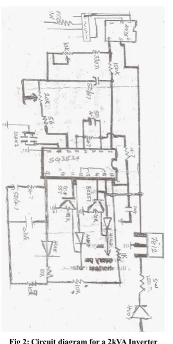
III. SELF-CHARGING INVERTER PROCESS The block diagram of a practical self-charging inverter [1] and circuit diagram for 2kVA [2] are presented below. The self-charging inverter is an electronic device that produces an alternating output from a direct current input or supply from 12V battery.
When inverter is connected to the power supply, the AC voltage is converted to DC by bridge rectifier circuit which is used to change the 12V battery.
International Journal of Emerging Technology and Advanced Engineering
Website: www.ijetae.com (ISSN 2250-2459,ISO 9001:2008 Certified Journal, Volume 3, Issue 12, December 2013)
[image:2.595.316.547.135.306.2]695
The converted voltage, 12V AC gets to the transformer via the switching stage, the signal will be stepped up from 12V AC to 220V AC before the output will be supplied to the load and small to a low input charger that converts the AC voltage to DC by bridge rectifier circuit that charges the 12V battery. The relay switches to the DC operators to power the load connected to the inverter.Fig 1. Block diagram of a practical self-charging inverter
Fig 2: Circuit diagram for a 2kVA Inverter
The circuit diagram [3] for 250 – 5000W inverter that could be made self-charging by connecting the charger to its batteries while drawing current from the output of the inverter.
This implies that any inverter could be connected to self-charging inverters by incorporating the new charger.
Fig 3 Circuit Diagram for 250 – 5000W Inverter that can be incorporated with charger to become self-charging inverter
IV. EXPLOITATION POSSIBILITIES
There exist numerous ways to exploit the energy from a self-charging inverter making it very useful and dependable source of electricity supply whenever there is no alternative source coming from national grid. Below are brief description of some of the applications.
A.In the homes: to operate electronic appliances such as television sets, cd player, lighting
B.In industries to power equipments requiring power less than 5kVA and provides continuous illumination
C.Offices: to operate office equipments and provide illumination
D.Business Enterprises: Most of the businesses require electricity supply for carrying out their day to day activities
E.In hospitals: self charging inverters can replace emergency back up generators that must be made available for any major medical health care facilities due to critical nature of work.
F.Behind Data Centres: self-charging inverters can be used to power computers, the heart of today’s industry. When servers and systems go down, communication can be lost, business stops, data is lost, workers sit idle and just about everything comes to a halt
V.SELF CHARGING INVERTER DEVELOPMENT The output capacity of the self charging inverters is determined mainly by Amp-Hours (AH) capacity of the battery as this determines how long one can run the battery. The 12V battery must be fully charged and the inverter must not be overloaded.
BATTERY CHARGER
BATTERY INVERTER
A C D C - +
[image:2.595.82.252.313.650.2]International Journal of Emerging Technology and Advanced Engineering
Website: www.ijetae.com (ISSN 2250-2459,ISO 9001:2008 Certified Journal, Volume 3, Issue 12, December 2013)
696
Many inverters of different types have been developed such as square wave modified sine wave, multilevel and pure sine wave inverters.The square wave inverters were the simplest, least expensive and early incarnation of inverter technology. They are seldom seen because of the low quality power. Modified sine wave inverters produce similar square wave output except that the output goes to zero volts for a time before switching positive or negative. They are simple low cost and suitable for many electronic devices except for sensitive or specialized equipment such as computers, laser printers, microwave, ovens, fluorescent lighting audio equipment. A pure sine wave inverter produces nearly perfect sine wave output (typically below 3% total harmonic distortion) that is essentially the same as utility supply grid power thus it is compatible with AC electronic devices.
All equipments sold in the market are designed for a sine wave hence sine wave inverter will guarantee that the equipment work to its full specification. Sine wave inverters are the most expensive but they also deliver the most consistent wave output. The multi level inverter is a power electronic system that synthesises a desired voltage from several levels of a desired voltage from several level of direct current voltage as inputs. The advantages of using multilevel topology include reduction of power rating of power devices and lower cost. There are three topologies: diode clamped inverter, flying capacitor inverter and cascaded inverter.
However, these different types of inverter require charging of the batteries after depletion (use) and this calls for a self-charging inverter that constantly recharges its battery when in use.
VI.
SELF-CHARGING INVERTER’S POTENTIAL The application of self-charging inverter to generate electricity is limited to the capacity of both the battery, in terms of Amp-Hour and output capacity of the inverter.The availability of numerous brand of deep cycle batteries of high Amp-Hour ratings up to 200AH gives the self charging inverter its potentials.
Researchers have shown that the potentials for self charging types is more than five times the potential of wind, solar, osmotic power due to its ability to deliver 24/7 daily in any part of the continent
VII. EARLY INVERTERS
From the late nineteenth century through the middle of the twentieth century, DC to AC power conversion was accomplished using rotary converters or motor generator sets (M-Gsets). In the early twentieth century, vacuum tubes and gas filled tubes began to be used as switch in inverter circuits. The most widely used tube was the thyratron.
The origin of electromechanical inverters explains the source of the term inverter. Early AC-to-DC converters used an induction or synchronous AC motor direct-connected to a generators commuter reversed its connections at exactly the right moments to produce DC – AC later development is the synchronous converter, in which the motor and generator windings ar combined into one armature, with slip rings at one end and a commutated at the other one field frame. The result with either is AC in, DC out. With an M-Gset, the DC can be considered to be separately generated from the AC; with a synchronous converted, in a certain sense it can be “mechanical rectified AC”. Given the right auxiliary and control equipment, an M-Gset or rotary converter can be “run backwards”, converting DC to AC.
Hence an inverter is an inverted converter. Since early transistors were not available with sufficient voltage and current readings for most inverter applications, it was the 1957 introduction of the thyristor or silicon-controlled rectifier (SCR) that initiated the transition to solid state inverter circuits.
VIII.
THE INNOVATIONThe self-charging inverter though costlier than any inverter is still the newest, most promising renewable energy technology cheaper than fuelless engine that produces the same capacity. The self-charging inverters could be in modules of 5kwatts with separate battery to power heavy duty equipments. It was noticed that the output remains constant irrespective of the number of the similar batteries connected in parallel and used with the self-charging inverter except that input current increases making the self-charging inverter to be more stable than when a single battery is used.
Also, using battery of high Amp-Hour ensure stability of the self-charging inverter output voltage. Once the rate of discharging the batteries is equal to the rate of charging the batteries when in use, the output voltage remains constant courtesy of the charger, the self-charging inverter could operate 365days without any interruption.
This is an ideal cheaper renewable energy source than fuelless engine that produces the same output power up to 5kwatts. This technique has been tested and proved reliably steady.
IX. FUTURE PROSPECTS
International Journal of Emerging Technology and Advanced Engineering
Website: www.ijetae.com (ISSN 2250-2459,ISO 9001:2008 Certified Journal, Volume 3, Issue 12, December 2013)
697
X.APPLICATIONS(i) DC power source utilization: inverter designed to provide 115V AC from the 12V DC source provide in an automobile. The unit shown provides up to 1.2 amperes of alternating current, or enough to power two sixty watt light bulbs.
An inverter converts the DC electricity from sources such as batteries, solar panels, or fuel cells to AC electricity. The electricity can be at any required voltage; in particular it can operate AC equipment designed for mains operation, or rectified to produce DC at any desired voltage. Micro-inverters convert direct current from individual solar panels into alternating current for the electric grid. They are grid tie designs by default.
(ii) Uninterruptible power supplies: an uninterruptible power supply (UPS) uses batteries and an inverter to supply AC power when main power is not available. When main power is restored, a rectifier supplies DC power to recharge the batteries.
(iii) Induction heating: Inverters convert low frequency main AC power to higher frequencies for use in induction heating. To do this, AC power is first rectified to provide DC power. The inverter then changes the DC power to high frequency AC power.
(iv) High Voltage Direct Current power transmission (HVDC): with HVDC power transmission, AC power is rectified and high voltage DC power is transmitted to another location. At the receiving location, an inverter in a static inverter plant converts the power back to AC.
(v) Variable-frequency drives: A variable-frequency drive controls the operating speed of an AC motor by controlling the frequency and voltage of the power supplied to the motor. An inverter provides the controlled power. In most cases, the variable-frequency drive includes a rectifier so that DC power from the inverter can be provided from main AC power. Since an inverter is the key component, variable-frequency drives are sometimes called inverter drives or just inverters.
(vi) Electric vehicle drives: Adjustable speed motor control inverters are currently used to power the traction motors in some electric and diesel-electric rail vehicles as well as some battery electric vehicles and hybrid electric highway vehicles such as the Toyota Prius, BYD e6 and Fisker Karma. Various improvements in inverter technology are being developed specifically for electric vehicle applications. In vehicles with regenerative braking, the inverter also takes power from the motor (now acting as a generator) and stores it in the batteries.
XI. ADVANTAGES OF INVERTERS
1. Outback inverters are designed to support a wide range of appliances including the residential, commercial appliances and for mobile use
2. Outback inverters are the best when it comes to power back up
3. The Nocria inverters have an inner drying function designed to prevent the growth of mould and fungus
4. Inverter are more portable and lighter weight, making them easier to manoeuvre around the job site
5. Inverters offer high-quality, multi process welding capacities so that one machine can handle stick, MIG, TIG, FC, AW are going and even pulsing 6. The energy produced is clean and non-polluting 7. There is no carbon dioxide or any other
by-products released, it produces no greenhouse gases or other waste
8. It is a renewable energy that will help reduce our reliance on the burning of fossil fuels.
9. The electricity supply is constant and efficient 10. Once you’ve constructed it, the energy is free
because it comes from batteries that are constantly recharged
11. It produced electricity reliably 12. Insignificant or low maintenance cost 13. No environmental impact
14. Deep cycle batteries last for 5 years 15. Isolated energy generation
16. No need to connect to the electricity grid 17. Possesses no threats to life and properties. 18. Occupies small area depending on its size 19. self -recharging when in use
XII. DISADVANTAGES OF INVERTERS
1. The disadvantage of using micro inverter is additional up-front cost
2. Not ideal for inductive AC and motor loads 3. Sensitive electronic devices can be damaged by
poor wave forms by low batteries.
4. Installing inverter at home may cause regulators of fans to go out of work
5. Waste of power when in use
6. On the flipside, portable inverter generators are more costly than the ordinary generators
7. Reduced efficiency, more complexity, increased cost.
XIII. CONCLUSION
International Journal of Emerging Technology and Advanced Engineering
Website: www.ijetae.com (ISSN 2250-2459,ISO 9001:2008 Certified Journal, Volume 3, Issue 12, December 2013)
698
However, the introduction of self-charging inverter can compete reasonably with those of either generators or any inverter that is already in use for similar purpose.Self-charging inverter potentials can be fully utilized by existing that the inbuilt charger recharges the batteries at the same rate that the DC discharges that the battery when drawing current from the battery.
REFERENCES
[1] Abraham, Keith Billing and Tylor More 2009. Switching power supply design, third edition McGraw Hill ISBN 0-07-148272-5 [2] Barry G. Woolard 1984. Practical Electroncis, United Kingdom
McGraw Hill Book Company UK Ltd. Pp 789 – 802
[3] Basford L. And Henry J. 1978. Electronics Made Simple, United Kingdom, W.H. Allen and Co. Limited pp. 500 – 503
[4] Bedford, B.D. and Hoft, R.G. 1964. Principle of Inverter Circuit, New York. Join Wiley and Sons pp 120 – 220
[5] Bedord B.D., Hoft R.G., et al 1964. Principle of Inverting. John Wiley and Son, New York, Pp 211 – 213.
[6] Benson F.A. Harrison D. 1995. Electric Circuit Theory, English Language Book Society, London.
[7] Berndt D and Taunton 1993. Maintenance-free batteries: lead-acid, nickel/cadmium, nickel/hydride: A handbook of battery technology Somerset England
[8] Bode H and Wiley 1995. Handbook of Batteries, D. Linden (2nd Ed), McGraw-Hill (2nd Ed), NY
[9] Chiang S.J. and Liaw C.M 2001. Single phase and three phase wires transformer inverter IEEE proc. Electric power application vol. 14
[10] Christopher Basso 2008. Switch mode power supplies, Spice I.J. modulation and practical design and Graw Hill ISBN 0071808587 [11] Edward Hughes 1995. Electrical Technology, Prentice Hall; 7
edition
[12] Fitzgbrald Higginbotham Gabriel 1982. Basic Electrical Engineering. McGraw Hill International Book Company
[13] Grafham D.R. and J.C. Hey 1994. SCR Manual editors, [14] Inverter FAQ Power Stream 2006. Inverter FAQ Retreived on 08
– 11 – 2006
[15] John C. Mons 1987 Electronic Practical Application and Design, Edward Arnold Company, Auckland. P. 105
[16] John Wesley & Son Chichester New York Brisbank Torinio [17] Levy S.C. and Bro P. 1994. Plenum, Battery hazards and accident
prevention
[18] Malcolm Plant 1990. Basic Electronics, Diodes and Transistor, Second Edition, Holder and Strong. Pp 121 – 123.
[19] Mazda, F.F. 1973. Thyristor control. New York: Halsted Press Div. of John Wiley and Sons pp 40 – 430
[20] Owen, Edward L. 1996. “Origins of the Inverter”. IEE Industry Applications Magazine: History Department
[21] Paule Gray, Campbell L. Scarle 1968. Electronic Principle Physics Model and Circuits
[22] Power Electroncis: Energy Manager for Hybrid Electric Vehicle. Oak Ridge National Library Review 33(3) U.S. Department of Energy. Retrieved 08 – 11 – 2006.
[23] Rodriguez, Jose et al August 2002. “Multilevel Inverters: A Survey of Topologies, Controls and Applications” IEEE Transaction on Industrial Electronics 49(4). Pp. 724 – 738 IEEE. [24] Shepherd J. Et al 1977. Higher Electrical Engineering, Pitman
Publishing Ltd, London.
[25] Theraja B.L. and Theraja A.K. 1959. Electrical Technology by Chand and Company Ltd 22nd Edition. Pp. 3360 – 3367, 2429 – 2431.
[26] Theraja B.L. and Theraja A.K. 1964. Principle of Electroncis. Pp. 453 – 467, 485 – 487, 504 – 511
[27] Theraja B.L., Theraja A.K. 2002. A Text book of Electrical Tehcnology, S. Chand and Company, India.
[28] Tom Duncan 1982. Physics, Textbook for Advanced Level Students formerly Senior Lecturer in Education, University of Liverpool. Pp. 498 – 499 & 509