International Journal of Emerging Technology and Advanced Engineering
Website: www.ijetae.com (ISSN 2250-2459,ISO 9001:2008 Certified Journal, Volume 5, Issue 6, June 2015)
194
Finite Element Analysis of Flexible Wedge Type (2”#150) Gate
Valve
Sonali Mantati
1, A. N. Surde
21
Department of Mechanical Engineering, Walchand Institute of Technology, Ashok Chowk, Solapur-413006, Maharashtra, India.
2Assistant Professor, Mechanical Engineering Department,Walchand Institute of Technology, Ashok Chowk, Solapur-413006,
Maharashtra, India.
Abstract—Gate valve sometimes called as sluice valve. As it’s name implies it is used to either stop or allow the flow of fluid from pipeline. A gate valve can be used for a wide variety of fluids and provides a tight seal when closed. Gate Valves are designed to suit a wide range of applications in Refineries, Petro-chemical Complexes, Fertilizer Plants, Power Generation Plants (Hydro - electric, Thermal and Nuclear) Steel Plants and Allied Industries. The main objective of this paper is to create the assembly of gate valve. After words to do the analysis of assembly using finite element method technique. Analysis of the assembly is done for following three position: when the valve is in fully closed condition, when valve is partially opened or closed condition, and when valve is in fully opened condition. Analysis to be done to find out the stresses and deformation developed.
Keywords— Valve body, Wedge, Finite Element Analysis.
I. INTRODUCTION
Valves are important mechanical devices/components of a piping system that control the flow and pressure in the process. The flow may consist of liquid, gas, vapour, or slurries. Depending on the phase of the flow material, different types of valves are available in practice, which are namely: Gate, Globe, Plug, Ball, Butterfly, Check, Diaphragm, Pinch, Pressure relief, and control Valves. In our studies, we will focus on the Gate valve. A Gate valve (also named as Sluice Valve) is a valve that opens by lifting a round or rectangular gate/wedge out of the path of the fluid. These valves are used for regulating flow, but many are not suited for this purpose, having been designed to be fully opened or closed. When fully open, the typical gate valve has no obstruction in the flow path, resulting in a very low frictional loss2. On the contrast, when the gate valve is fully closed, there are many obstructions in the flow path which in turn produces high frictional losses. To avoid or minimize the frictional losses, the impact of stress distribution on the parts of the gate valve is important to recognize in advance, before manufacturing of gate valve.
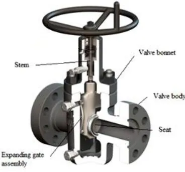
[image:1.612.349.533.302.473.2]Figure 1 show the schematic of a basic gate valve, where various parts of the valve are highlighted. Let us look at them in brief.
Fig. 1: Schematic illustration of a basic gate valve.
i) Valve Body:
The Valve body is the first boundary of a pressure valve. It acts as the main element of a valve assembly, as it holds all the parts together in the frame work. The ends of a valve body are designed in such a way that external piping or equipment nozzle can be connected to the valve body.1
ii) Valve Bonnet:
International Journal of Emerging Technology and Advanced Engineering
Website: www.ijetae.com (ISSN 2250-2459,ISO 9001:2008 Certified Journal, Volume 5, Issue 6, June 2015)
195 iii) Valve Trim (seat, gate, stem):
The internal elements of a valve are collectively referred to as a valve's trim. Typically, it includes a seat, disk/gate, stem, and sleeves (not shown in the schematic). For a valve having a bonnet, the disk is the third primary principal pressure boundary. The seat or seal rings provide the seating surface for the disk. The stem is responsible for positioning the disk. It is typically forged and connected to the disk by threaded or welded joints.
iv) Valve Packing:
Most valves use some form of packing to prevent leakage from the space between the stem and the bonnet. It is commonly a fibrous material (eg. flax) or other compound (eg. Teflon) that forms a seal between the internal parts of a valve and the outside, from where the stem extends through the body.1
Objective: The objective of the present work is to find out stress distribution and deformation pattern at three position of wedge i.e when wedge is at fully closed position, at partially opened/ closed position and fully opened position.
II. LITERATURE REVIEW
In the recent year, Dr. Gurudutt Sahni2 et al, focuses on the finite element analysis of wedge. In this paper each component of gate valve was developed in solid works and analyzed using Ansys software. The main purpose is to find out stresses developed on wedge due to different structural load and to see how structural load analysis helps in modification in design of wedge gate valve. Finally the results obtained from analytical theory and finite element analysis software was compared.
Dr. K. H. Jatkar3 et al, also focuses on the finite element of gate valve. The critical components of gate valve i.e valve body, stem and wedge were modelled using CATIA software and further analysis carried out on these components to find out the stresses and strains developed due to internal fluid pressure. Finally, the results obtained from finite element method software and classical analytical theory was compared.
As a case study, Narayan Dharashivakar4 et al, analyzed the stress pattern using 3 dimensional photo elasticity.
The experimental work has been carried out on the wedge which was failed working condition. In the experimental work model of wedge was made and using photo elasticity stress pattern was found out. After that, the experimental results were compared with the finite element results. It has been concluded that, the stress concentration factor at stress concentration region is observed to be more that theoretically required and the failure may be because of impact of T-Nut on surface of wedge.
The measurement of stress concentration in machine component is of considerable importance because mechanical failures of such pats are frequently due to fracture which is initiated through the sections having stress concentration. Mr. Pradip Patil5 et al, carried out design of gate valve body using cad technologies. The main purpose is to find out the stresses and strains developed due to internal pressure using finite element analysis.
In the present state of the art, K. Punitharani et al.6 [2010] established the temperature distortion and residual stress field developed during hard facing gate valve by finite element analysis. The work encompasses, a three dimensional solid model generation and simulations using ANSYS parametric design language (APDL) code. After simulations, residual stresses were compared and validated by x-ray diffraction technique.
III. MODELLING OF GATE VALVE ASSEMBLY
3D models are easier to interpret. Alternative designs can be investigated by using 3D models.3D models can be used to perform finite element analysis (stress, deflection, thermal, drop test….), to perform motion analysis. 3D models can be used directly in manufacturing, Computer Numerical Control (CNC).
There are basic three types of three dimensional computer geometric modelling methods7:s
Wireframe Modelling
Surface Modelling
Solid Modelling
International Journal of Emerging Technology and Advanced Engineering
Website: www.ijetae.com (ISSN 2250-2459,ISO 9001:2008 Certified Journal, Volume 5, Issue 6, June 2015)
196
Fig.2 Schematic illustration of Gate Valve Assembly
Meshed model of Gate Valve Assembly
Fig.3 Meshed model of Gate Valve Assembly
Boundary Condition:
To do analysis it necessary to give boundary condition, in our case body is fixed and fluid pressure of 2MPa is applied.
(A) On wedge when it is in fully closed condition as shown in fig.4
Fig.4 Boundary condition applied on Gate Valve
(B) And in second case i.e when wedge is in partially closed position then fluid pressure is applied partially on the wedge and partially on inner portion of body and seat rings as shown in fig.5
Fig.5 Boundary condition applied on Gate Valve
(C) When wedge is in fully open condition the bonnet is fixed and fluid pressure is applied on inner surface of body as show in fig6
International Journal of Emerging Technology and Advanced Engineering
Website: www.ijetae.com (ISSN 2250-2459,ISO 9001:2008 Certified Journal, Volume 5, Issue 6, June 2015)
197 IV. RESULTS &DISCUSSION
Stress and deformation is found out with the analysis software Ansys at three condition.
1. Stress and deformation when wedge is in fully closed condition:
(A) Deformation Diagram:
Fig.7 Schematic illustration of Deformation Diagram
(B) Stress Diagram:
Fig.8 Schematic illustration of Stress Diagram
2. Stress and deformation when wedge is partially opened:
(A) Deformation Diagram:
Fig.9 Schematic illustration of Deformation Diagram
(B) Stress Diagram:
Fig.10 Schematic illustration of Stress Diagram
3. Stress and deformation when wedge is fully opened condition:
(A) Deformation Diagram:
Fig.11 Schematic illustration of Deformation Diagram
(B) Stress Diagram:
International Journal of Emerging Technology and Advanced Engineering
Website: www.ijetae.com (ISSN 2250-2459,ISO 9001:2008 Certified Journal, Volume 5, Issue 6, June 2015)
198
V. CONCLUSION
In the conclusion, the emphasis on the analysis of the gate valve with 2” #150 type was made.
The analysis of mechanical component is done to find out the stress pattern or behaviour of the component. The stresses and deformation obtained from analysis are tabulated as below.
Gate Valve
Assembly
Stress
(N/mm2)
Deformation
(mm)
Min Max Min Max
When
wedge is at
fully closed
condition
4.2*
10-7
6751.5 0.9857 8.8665
When
wedge is at
partially
opened
condition
9.2*
10-19
1881.2 0.23399 2.1059
When
wedge is at
fully opened
condition
6.3321 56.989 0.0025426 0.0022884
REFERENCES
[1] www.seridium.com
[2] Dr. Gurudutt Sahni, Balpreet Singh, “To Perform the Structural Analysis on Wedge Type Gate Valve and it’s Optimization using F.E.A, IRJMST, Vol.5, Issue 5, 2014, pp.188-194
[3] Dr. K.H.Jatkar, Sunil S. Dhanwe, “Finite Element Analysis of Gate Valve”, International Journal of Engineerring and Innovative Technology, Vol-2, 10 April 2013, PP: 277-281
[4] Narayan Dharashivkar, Prashant Patil, Krishnakumar Joshi, “3-Dimensional Experimental and Finite Element Stress Analysis of C.I Wedge of Sluice Valve”, Machine Design, Vol-5, [2013], PP: 57-60 [5] Mr. Pradip Patil, Prof. V. R. Gabhire, “Structural Analysis of Gate
Valve Body using F.E.A”, International journal of Engineering Research and Techology, Vol.3, Issue 6, June2014, pp. 1815-1818 [6] K Punitharani, N Murugan, S.M. Shivagami, “Finite Element
Analysis of Residual Stresses and Distortion in Hard Faced Gate Valve”, Journal of Scientific and Industrial Research, Vol-69, Feb 2010, PP: 129-134
![INtegrateD Corporate [2012]](data:image/gif;base64,R0lGODlhAQABAIAAAP///wAAACH5BAEAAAAALAAAAAABAAEAAAICRAEAOw==)