2017 International Conference on Computer Science and Application Engineering (CSAE 2017) ISBN: 978-1-60595-505-6
IMU-assisted RSS Fingerprint-Based Localization
with Cylindrical Antennas Array
Jie Wu1, Minghua Zhu2*, Haibo Zhang1 and Lei Wang1
1
The Third Institute of the Ministry of Public Security, No. 339 N. Bisheng Rd., 200001 Shanghai, China
2
MOE Research Center for Software/Hardware Co-Design Engineering and Application, East China Normal University, 200062 Shanghai, China
ABSTRACT
The recent growing interest for RFID based localization has created a need for easier installation and more accurate for indoor positioning. The CAA (Cylindrical Antennas Array) that consists of twelve directional antennas has been developed in this paper. In the area covered by directional antennas, only one antennas array is needed to locate the tags with the proposed method. Based on the designed system, the paper proposed a fingerprint-based localization with the aid of IMU (Inertial Measurement Unit), which is used to assist the filtering of received RF data and get the knowledge of the efficiency of current fingerprint database (radio map). In addition, the received data vectors by CAA have twelve dimensions which could improve the fingerprint-based localization accuracy. The experiments were conducted with the proposed system to position the tags and make a comparison with other indoor localization methods. The result shows it could increase the positioning accuracy of tags and enhanced the performance of RSS-based fingerprint localization.1
INTRODUCTION
RFID (Radio Frequency Identification) technology is widely used in many applications such as logistics, health care, and goods retail for its low power consumption and high cost performance. Most of applications are dependent on the location based information, so the RFID based localization technology is increasingly drawing more attention.
relative tags preset in the location area. The positioning accuracy is decided by the density of relative tags. Ni et al. [7] presents a location sensing prototype system (LANDMARC)2 that uses RFID technology for locating objects inside buildings. Sun [8] put forward an indoor location algorithm based on reference tags. The positioning accuracy is decided by the density of relative tags. (3) RSS fingerprint-based localization [9-10] bases on the radio map composed of RSS vectors associated with corresponding tags locations. Park et al. [11] presents the development of a hybrid-tracking system that integrates BLE (Bluetooth Low Energy) technology, motion sensors, and building information model. Yinet al. [12] proposes a location estimation using model trees to reconstruct radio map using real-time signal-strength readings received at the reference points. The drawback of this method is that radio map needs to be rebuilt if the surrounding environment is changed.
In this work, we have designed a CAA (Cylindrical Antennas Array) reader which consists of twelve directional antennas. In the area covered by directional antennas, only one CAA is needed to locate the tags with the fingerprint-based matching method. Fingerprint-based matching is divided into offline stage and online stage. During the offline stage, the CAA received twelve dimensions of tags data and corresponding RSS from twelve directional antennas to generate the radio map. During the online stage, the RSS of tags is received by CAA and is filtered with the assisted of IMU (inertial measurement unit), and the RSS vector is compared with the vectors of radio map to get the most likely position of tags. Through the auxiliary of IMU, we can know whether radio map is outdate and needs to be updated.
This paper is organized as follows: the next section is the overview of the system. The proposed algorithm is described in section 3 and three experiments about the proposed method are conducted in section 4. Finally, the discussion and conclusion are made in section 5 and section 6.
SYSTEM OVERVIEW
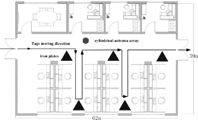
As shown in Figure 1, the system is constituted by three parts: cylindrical antennas array reader, tags and server terminal. The CAA reader consists of twelve directional antennas. The twelve directional antennas adopt twelve independent radio frequency receiving chips to receive the tag information simultaneously. Then received data are transmitted to the MCU (Micro Control Unit) in the reader. The MCU receives and summaries the data, and sends to the data to the server terminal, in which the arithmetic is processed. In order to guarantee the stability of the system, the CAA is mounted in the area where the radius is less than 100m. Within the scope, the only one CAA is needed to achieve the goal of localization.
fingerprint-based positioning. We could judge whether the radio map is outdate and need to be updated with credibility.
Figure 1. The distribution of cylindrical antennas array and the location area.
PROPOSED ALGORITHM
The paper proposed a method of using twelve dimensions RSS as fingerprint for indoor localization. We use IMU as RSS smooth filter for two reasons. (1) Suffered by the influence of multipath in the indoor environment, RSS is fluctuant even in the same position. A kind of filter method should be used to filter the RSS to get a relative stable value. (2) In the process of receiving the signal strength for an unknown tag, it is impossible for us to know whether the RSS is collected in the same place without the help of tag carrier. The displacement which is calculated by the IMU is assumed to take a sudden change. Based on this assumption, we use the IMU for to filter the received signal strength. When displacement is calculated to be a big change, the RSS in changed position may produce little influence for the original position. When displacement is calculated to be a little change, the RSS in changed position (or no change at all) may produce important influence for the original position.
[image:3.612.124.473.550.668.2]Fingerprint-based Localization
The fingerprint-based localization is divided into two phases: offline phase and online phase. In the offline phase, we collected the RSS vectors of twelve dimensions and corresponding position to build the radio map of the system. In the online phase, when the CAA received the RSS information, the vectors would be compared with radio map to find the K nearest positions, and then we got estimated location of the tags with the KNN algorithm.
OFFLINE PHASE
The radio map is generated in the offline phase. When the tag carrier stands still in the reference position, the signal strength of specific tag is collected by reader to generate fingerprint database. As shown in Figure 2, the CAA reader collects RSS data of 12 dimensions in a fixed time interval when the person carrying tag in one position. The data is filtered by smooth filter, and then the filtered data is summarized to get corresponding relations between RSS vectors and tag position. The radio map would be created when the RSS of all corresponding reference points are measured.
Every RSS collected in each antenna in CCA is mapped to one dimension, and there are 12 dimensions in total. The RSS value is -130 dbm to -40 dbm. If one of antennas didn't receive the data, we take the RSS by the antenna as -130 dbm. In order to simplify the dimensions of data, we use the 16 of RSS level, and the RSS from -130 dbm to -40 dbm is compressed to level 0-15, and the compression equation is given by:
(| | 40*16) 130 40
X X floor
(1) Where X′ is the compressed vector, the floor function is used for rounding down the data.
ONLINE PHASE
In the online phase, the tags signal strength is received by CAA and the information is denoted as Y which has twelve dimensions. After filtered by IMU assisted smooth filter, the online RSS is denoted as Y′. The Y′ is compared with the RSS vector in radio map. We use the cosine similarity to measure the distance between two vectors. The similarity equation is given by:
cos
| | | |
t t
t
X Y
X Y
(2) Where the Xt is the vector in the radio map, Y′ is the filtered online RSS. With equation
IMU Assisted Weighted Smooth Filter
In the offline stage, the RSS of tags is collected when the tags keep still in the location area. In the online stage, however, the moving speed and direction of the person carrying tags are not regular. When the person takes a sudden move, it would result into big deviation for RSS measurement. In this paper, we adopt IMU assisted weighted smooth filter for the RSS, and use the IMU to measure the relative displacement of person movement, because the IMU is insensitive to the environment change. For IMU inertial navigation calculation, we adopt IMU-Alone IEZ+ Method proposed in [13-14]. Several methods for heading drift reduction: ZARU (Zero angular rate update), HDR (Heuristic Heading Reduction) and electronic compass, have been implemented and integrated into the Kalman-based IEZ framework to estimate the position and attitude of a person while walking. The algorithm performs well and the accumulated errors of approximately 1% of the total traveled distance. The different weights are used in the function for different relative displacement. The weighted smooth filter is given by:
( ) ( )
s i i
X n
X i (3)Where X refers to the received RSS vector by CAA, the X (i) = {x1i, x2i … x12i}. The xji
is the RSS, which is received by jth directional antenna in ith time, where j = {1, 2 … 12}.
The parameter s refers to the number of received times in a fixed time interval. The parameter α is the weight of filter and is given by:
( | 1) / ( | 1)
s i
j
S i i S j j
(4)The expression S (i| i-1) is relative displacement from previous time (i-1) to ith time of
received data by CAA.
We track the position of tags when the tag is moving. In this situation, the IMU is used to get a relative accurate RSS. We assume that when the tag point is leaving the location area, the far it leaves, the large bias of RSS is. The explanation of the proposed smooth filter is that for the received signal strength in a fixed time interval, the less tag moves, the greater the weight of the position is.
Fingerprint Effectiveness Judgment
THE CREDIBILITY OF THE RESULTS
The credibility of the positioning results is determined by the two factors. (1) Taking the last estimated location of the tag as a reference position, we compared the relative displacement obtained by the RSS fingerprint-based method with the relative displacement given by IMU. If the deviation between the two relative displacements is big, credibility is low. If the deviation between the two relative displacements is small, it means that the credibility is high. In this way, the deviation between the two relative displacements is inversely proportional to the credibility of the positioning results. (2) The credibility of the positioning results should be a positive number and no greater than 1. So the experience equation is given by:
1
1 (| |)
i P P
Where γi is the credibility of the ith positioning results,0<γi<1. The positive parameter
β is introduced to control the range of γi and its experience value is 0.9. The ΔP is the
relative displacement given by IMU, and ΔP′ is the relative displacement obtained by the RSS fingerprint-based method. In general, it is thought that the calculated positioning location is reliable when the γi is higher than 0.6 in practice.
FINGERPRINT EFFECTIVENESS ACCORDING CREDIBILITY
The fingerprint-based localization is sensitive to the surrounding environment, so it is important to get the knowledge of environment change and whether the radio map is still effective. If the fingerprint database is outdate and not timely rebuilt, it would cause the location estimation deviation. With the credibility of the positioning results, we can get whether the radio map is outdate and need to be updated when the credibility is below a certain threshold. The experience value of the threshold is 0.4.
EXPERIMENTS
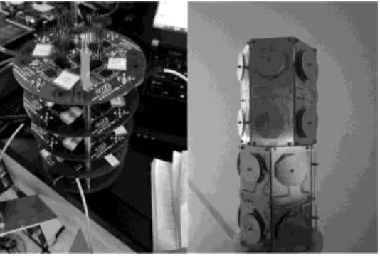
[image:6.612.140.452.480.582.2]We conducted three experiments with the following system. We adopted 2.4 GHz RFID chip Nordic NRF52832 and used NRF24LE1 chip as active RFID tags chip. As shown in Figure 3, twelve directional antennas are installed at two layers, and each layer includes six antennas. In the same layer, the angle between every two antennas is 120 degrees. The angle between two adjacent antennas is 30 degrees in different layers. Thus twelve antennas are distributed in the direction of 360 degrees, which improves the resolution of angle of arrival. The send power of tags is 4 dbm and the IMU chip which is integrated into the tags is ADXL355. The size of the directional antenna is 10 cm x 4 cm rectangular antenna, and twelve directional antennas are integrated into the CAA. In CAA, the main control chip is STM32F407. The server terminal configuration is Quad - Core Intel Core i5, and 8 GB RAM.
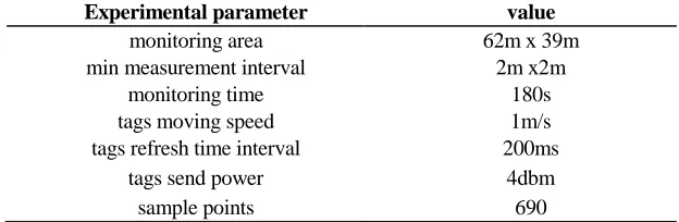
TABLE I. EXPERIMENTAL ENVIRONMENT PARAMETER SETTINGS.
Experimental parameter value
monitoring area 62m x 39m
min measurement interval 2m x2m
monitoring time 180s
tags moving speed 1m/s
tags refresh time interval 200ms
tags send power 4dbm
Figure 3. The hardware of system and the CAA.
Experimental environment setup is shown in TABLE I. We conducted three experiments: the first experiment showed the comparison of credibility before the environment changed and after the environment changed. The second experiment showed the influence of different grid size to the positioning accuracy. The third experiment showed the comparison of three different localization methods.
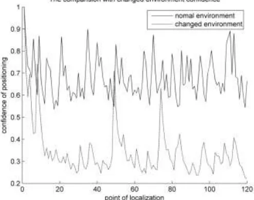
The Comparison of Credibility in Different Environment
Figure 4. The comparison of credibility in different environment.
The Influence of Different Grid Size to the Positioning Accuracy
In the proposed system, we adopted the grid size of 1m x 1m. However, different grid size would cause different positioning accuracy. In order to show the influence of different grid size to the positioning accuracy, we made the following experiment. Three kinds of grid size of 1m x 1m, 2m x 2m and 4m x 4m are adopted in this experiment and experimental environment setup is the same as experiment 1. Under this condition, we calculated the positioning deviation for three different grid sizes. As is shown in Figure 5, the positioning deviation for the grid size of 1m x 1m, 2m x 2m are basically the same, and the deviation for the grid size of 4m x 4m is bigger.
Figure 5. The influence of different grid size to the positioning accuracy.
The paper [15](omnidirectional antennas array based method) receives the valid data using total 17 SR (sensor reader) and makes the training and online matching by means of ANN training. The paper uses the combination of the directional antennas and omnidirectional antennas for positioning. In this experiment, we adopt the six directional antennas deployed in different corners to receive the data, and used Matlab Neural Network Toolbox for ANN training and online matching. Experimental environment setup is the same as experiment 1. We use trilateral positioning method proposed in [4] with the classic model between RSS and distance. We adopt the six directional antennas deployed in different corners and selected 3 effective antennas. We compared positioning accuracy of three methods, and the result is shown in TABLE II.
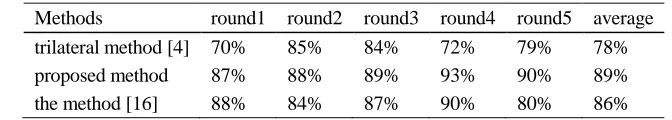
TABLE II. THE COMPARISON OF THREE DIFFERENT LOCALIZATION METHODS.
Methods round1 round2 round3 round4 round5 average
trilateral method [4] 70% 85% 84% 72% 79% 78%
proposed method 87% 88% 89% 93% 90% 89%
the method [16] 88% 84% 87% 90% 80% 86%
As shown in the table, the accuracy of trilateral positioning method is lowest, which could have relationship with the current test environment because the environment is complex. Because the density and quality of the directional antennas, the accuracy of the algorithm is not as high as depicted in the omnidirectional antennas array based method and the average position accuracy is 86%. The proposed algorithm in the paper reaches 89% which is basically as equal as the omnidirectional antennas array based method. However, the proposed algorithm needs only one point layout, so it is more convenient than omnidirectional antennas array based method.
DISCUSSION
The paper presents a novel RSS based indoor localization with the fusion technology of CAA readers and IMU. The proposed structure was compared with two previous indoor location algorithms in order to show the benefits achievable by the proposed approach. It is shown that the proposed solution has better cost performance and higher positioning accuracy. The data collected in the experiment and the method to calculate the credibility for the positioning method can be used to further develop credibility systems. In the end, the three experiments also show the effective of proposed localization method and system.
CONCLUSIONS
The paper designed a cylindrical antennas array reader and implemented IMU-assisted fingerprint based indoor positioning system. This CAA is easy to be mounted and could receive twelve dimensions data at the same time to achieved high positioning accuracy. In the process of received signal strength, the paper put forward an IMU based filtering method to smooth the received information and get the more stable signal strength. In addition, the credibility of the localization and fingerprint database effectiveness was proposed as positioning quality metrics and fingerprint effectiveness judgment.
The proposed system includes two benefits for the IMU-assisted fingerprint based indoor localization. Firstly, the paper designed a reader which integrated twelve directional antennas. In this way, only one reader is used to conduct the fingerprint based indoor localization within the scope of the covered by RF signal. The reader receives twelve dimensions signal data for one tag at the same time, which increased the tags positioning precision and decreased the setting cost. Secondly, with the aid of IMU, the relative displacement of the tag movement is measured. The gathered RSS which are not always in the same position are filtered by weighted smooth filter with IMU. Then a stable and reliable RSS value are calculated and put into the database to be compared with fingerprint to get a more accurate tag position.
Future works will focus on quantitative investigations on CAA characters. Though the RF simulation of antenna arrays will be researched to find better solution for the CAA based localization. Also, different techniques in CAA and IMU integration will be researched to get a more accurate and robustness positioning result.
ACKNOWLEDGEMENT
The study was supported by Shanghai Technology & Science Administration Project (No.16511104800).
REFERENCES
1. Shi, X., and Ji, Z. 2015. “Indoor positioning system algorithm based on RFID,” Univ Psychol, 12(3): 779-796.
2. Xu, H., Ding, Y., Wang, R., Shen, W., and Li, P. 2016. “A novel radio frequency identification three-dimensional indoor positioning system based on trilateral positioning algorithm,” Journal of Algorithms and Computational Technology, pp.158-168.
3. He, T., Huang, C., Blum, B. M., Stankovic, J. A., and Abdelzaher, T. 2003. “Range-free localization schemes for large scale sensor networks,” International Conference on Mobile Computing and NETWORKING ACM, 2003:81-95.
4. Nowak, T., Hartmann, M., Zech, T., and Thielecke, J. 2016. “A path loss and fading model for RSSI-based localization in forested areas,” IEEE-APS Topical Conference on Antennas and Propagation in Wireless Communications, pp.110-113. IEEE.
5. Shi, W., Han, X., Du, K., and Li, J. 2016. “A Novel Solution for the Optimal Deployment of Readers in Passive RFID Location System,” Proceedings of the 2015 International Conference on Communications, Signal Processing, and Systems, pp.386-391. IEEE
7. Ni, L. M., Liu, Y., Lau, Y. C., and Patil, A. P. 2004. “Landmarc: indoor location sensing using active rfid,” J. Wireless Networks, 10(6): 701-710.
8. Sun, Y., Wang, H., and Bo, L. I. 2015. “Research of rfid indoor location algorithm based on reference tags,” Video Engineering.
9. Saab, S. S., and Msheik, H. 2016. “Novel RFID-based pose estimation using single stationary antenna,” IEEE Transactions on Industrial Electronics, 63(3): 1842-1852.
10. Koch, A., and Zell, A. 2016. “RFID-enabled location fingerprinting based on similarity models from probabilistic similarity measures,” IEEE International Conference on Robotics and Automation, pp.4557-4563, IEEE.
11. Park, J. W., Chen, J., and Yong, K. C. 2017. “Self-corrective knowledge-based hybrid tracking system using bim and multimodal sensors,” Advanced Engineering Informatics, 32, pp.126-138. 12. Yin, J., Yang, Q., and Ni, L. M. 2008. “Learning adaptive temporal radio maps for
signal-strength-based location estimation,” IEEE Transactions on Mobile Computing, 7(7): 869-883. 13. Foxlin, E. 2005. “Pedestrian tracking with shoe-mounted inertial sensors,” Computer Graphics &
Applications IEEE, 25(6): 38-46.
14. Jiménez, A. R., Seco, F., Prieto, J. C., and Guevara, J. 2010. “Indoor pedestrian navigation using an INS/EKF framework for yaw drift reduction and a foot-mounted IMU,” Positioning Navigation and Communication, pp.135-143. IEEE.