Systems
GC20-1859-4 File No. S370-01
A Guide to the IBM 3033
Processor Complex,
Attached Processor
Complex, and
Multiprocessor Complex
of System/370
This guide presents hardware, programming systems, and other pertinent information describing the significant new features and advantages of the IBM 3033 Processor Complex, Attached Processor Complex, and Multiprocessor Complex. Knowledge of a System/370 processor that has EC mode and dynamic address translation capabilities is assumed. This guide is intended to acquaint the reader with the com-ponents of 3033 configurations and to be of benefit in installation planning.
Associated with this guide are three optional supplements describing programming systems for the 3033 Processor Complex that support a virtual storage environment. Each supplement has its own form number and must be ordered individually, if desired. The optional supplements are: • as/Virtual Storage 1 Features Supplement (GC20-1752) • as/Virtual Storage 2 Single Virtual Storage (SVS)
Features Supplement (GC20-1753)
• Virtual Machine Facility/370 Features Supplement (GC20-1757)
--..-
--.-,-
-
-
---
--
-
----
--
-~-.-Fifth Edition (April 1979)
This edition is a major revision obsoleting GC20-1859-3. A discussion of the 3033 Attached Processor Complex configuration has been added and the new processor storage sizes have been included. Various other changes have been made as well.
This guide is intended for planning purposes only. It will be updated from time to time; however, the reader should remember that the authoritative sources of system information are the system library publications for the 3033, its associated components and its pro-gramming support. These publications will first reflect any changes.
Requests for copies of IBM publications should be made to your IBM representative or to the IBM branch office serving your locality.
A form has been provided at the back of this publication for readers' comments. If this form has been removed, address comments to: IBM Corporation, Technical Publications, Dept. 824, 1133 Westchester Avenue, White Plains, New York 10604. IBM may use or distribute any of the information you supply in any way it believes appropriate without incurring any obligation whatever. You may, of course, continue to use the information you supply.
PREFACE
It is assumed that the reader of this publication is familiar with System/310 architecture, features, and I/O devices that are common among System/310 processors in which EC mode is implemented. Knowledge of virtual storage and virtual machine concepts and advantages is also assumed. Such information can be found in other guide series
publications, such as ~ Guide to the IBM System/310 Model 168 for System/360 Users (GC20-1181), and system library publications.
This guide identifies the major facilities of the 3033 Processor Complex in Sections 05 through 20 but detailed explanations and advantages are given only for features or implementations that are different from those of most other System/310 processors with dynamic address translation capability. Additional, more detailed information regarding 3033 Processor Complex hardware and programming systems support can be found in system library publications.
The 3033 Multiprocessor Complex and 3033 Attached Processor Complex, which are tightly coupled multiprocessing configurations, are also discussed. This guide does not assume knowledge of multiprocessing concepts, hardware, or advantages, all of which are covered.
The total guide for the 3033 Processor Complex consists of this base publication (Sections 01 through 10), which covers 3033 Processor, 3036 Console, and 3031 Power and Coolant Distribution Unit hardware, and from one to three optional supplements (Sections 90, 100, and 110). The optional supplements describe the facilities of three of the IBM
programming systems that support a virtual storage environment using the dynamic address translation hardware of the 3033 Processor.. Each
optional supplement has its own unique form number and each supplement desired must be ordered separately and inserted in this base
publication, which is distributed without the automatic inclusion of any optional supplements.
The following optional supplements can be inserted in this base publication:
• OS/Virtual Storage 1 knowledge of OS MFT
(GC201752)
-• OS/Virtual Storage 2 Single Virtual Storage (SVS) Features Supplement (GC20-1153) - assumes knowledge of OS MVT
• Virtual Machine Facility/310 Features Supplement (GC20-1151) - does not assume knowledge of CP-61/CMS
All optional supplements also assume knowledge of virtual storage, dynamic address translation, and other new 3033 Processor and 3036 Console features as described in this base publication or appropriate system library documentS.. However, no optional supplement requires knowledge of the contents of any other optional supplement.
This base publication, as well as each optional supplement, begins with page 1 and includes its own table of contents and index,. The base publication or supplement title is printed at the bottom of each page as a means of identification .•
The optional programming systems supplements contain System/310 processor-independent information, unless otherwise noted, and are deSigned to be included in the guides for the 3031, 3032, and 3033
Base Publications DOS/VS Features Supplement (GC20-1756) A Guide to the IBM
System/370 Model 135 (GC20-1738)
A Guide to the IBM System/370 Model 138
(GC20-1785)
A Guide to the IBM System/370 Model 145
(GC20-1734)
A Guide to the IBM System/370 Model 148
(GC20-1784)
A Guide to the IBM System/370 Model 158 for System/310
Model 155 Users (GC20-1154)
A Guide to the IBM System/370 Model 158 for System/360 Users
(GC20-1781)
A Guide to the IBM System/370 Model 168 for System/310
Model 165 Users (GC20-1755)
A Guide to the IBM System/370 Model 168 for System/360 Users
(GC20-1781)
A Guide to the IBM 3031 Processor Complex and Attached Processor Complex of System/370
(GC20-1854)
I
A Guide to the IBM 3032 Processor Complex of System/310
(GC20-1858)
A Guide to the IBM 3033 Processor Complex, Attached Processor I
Complex, and Multiprocessor
Complex of System/370
(GC20-1859)
I
x x x
x
x x x SupplementsOS/VS1 OS/VS2 SVS Features Supplement (GC20-1752) x x x x x x x x x x x Features Supplement (Gc20-1753) x x x x
x
x x x VM/370 Features Supplement (GC20-1757) xx
x x x x xx
x x xCONTENTS
~ Publication Sections (Sections 01 through 70)
Section 01: Highlights of the 3033 Processor Complex, Attached
Processor Complex, and Multiprocessor Complex ,.
Section 05: 3033 Processor Complex Physical Components and
Technology . . . .
Physical Components ,.
Motor Generator Set , . .
Cooling • . ~ ~ ~ ~ . . . • .
Technology ,. . ,. .
Section 10: 3033 Processor Architecture Design and Functional
Components .. . ,. • . '. ,. . 'e • ,. ,. .• ,. • • ,. • • • ,e •
10: 05 Architecture Design and Processor Elements .. . ,. .
Architecture Design . . . , . . . ,. • ,. . . ,. ,. .. ,. '. .
Processor Elements and Features . ,. .. . . ,. .. .. . .. .
10: 10 Instruction preprocessing and Execution Functions ,. ,.
Instruction preprocessing Function
Execution Function . . . .
I.
.. ,. ,. ,.
10:15 Processor Storage and the Processor Storage Control
Function • . , . . ' ,e
I. ,. • • . • I. • ,.
• ."
Processor (Main) storage . . . ,. . .
Processor storage Control Function
10:20 Channels • _ • . . .
Channels and Directors Channel Bus Controller I/O Error Handling
10:25 Maintenance and Retry Function
Trace Unit • _ . . . . _ • •
Section 20: The 3036 Console for the 3033 Processor Complex ..
20:05 20:10 20:15 20:20 20:25 20:30 20:35
Components, Functions, and General Operation
Components .. . .. . ,. . .. . ,. . '.
Functions and General operation
Control Panel • . ,.
I. ,. ,.. ,. ..
CRT Display and Keyboard Diskette Drive and Diskettes
Display Frames . . . ,. .
Operator Frames . • ,. .
Service Frames . ,. ,. . ,.
Indicator/Logout Frames .
I. ,. ,. ,.
Console Configuration. . . Types of Configurations Normal Console Configuration
Maintenance Mode Console Configurations
Console Recovery Facilities .. . ,. ,.
serviceability Features . _ • • •
Voltage Monitoring
Fault Locating Tests . . '. ,.
1 6 6 7 7 8 9 9 9 10 14 14 16 24 24 27 36 36 44 44 46 46 49 49 49 51 52 56 57 59 60 66 68 68 68 70 72 75 76 76 76
Section 30: The 3033 Multiprocessor Complex . • • • . . • . 78
30: 05 General Description ,. ,. . . • . . . .. . . .. . 78
Introduction . . • • • . e • • • e • e • • • e • 78
General Definition of Multiprocessing . ,e • ,. e •• • , . . • 78
The 3033 Multiprocessor Complex Configuration . 80
Advantages of Tightly Coupled Multiprocessing
30:10
Advantages of Loosely Coupled Multiprocessing Configurations • • • • • ~ • • 4 • ~ • ~ • •
3033 Multiprocessing Architecture and Hardware 3033 Processor Complex and Multiprocessor Complex
96 98
Hardware Differences ~ • • ~ '. ,. .. • 98
prefixing • • '. '. ,. .• • '. '. • ,., .. .. .. ,. • • • ,. • 99
Processor Addressing , •.• ,. , • • 100
Time-of-Day Clock ~ • • ~ • ~ ~ ~
Interprocessor Programmed Communication .• ,. Interprocessor Hardware Communication ,. .• .,
• 100 • 101 • 103 30:15
30:20
Recording and Diagnostic programs. ,. ,. ,. .• Planning Considerations • ' . . .• • .• .• ,. .• ,.
• .. .• .• • 104
Planning for Maximum System Availability
Section 40: The 3033 Attached Processor Complex ~
40:05 General Description.. • • • ~
Components ,. • •
I.
3033 Model A Processor 3042 Attached Processor •3038 Multiprocessor Communication unit 3036 Consoles I . •• , . • • ,0 I . , . 4 , . I . . . . . I .
40:10 3033 Processor Complex and Attached Processor COmplex
• 105 • 105
• 108 • 108 • 108 • 110 • 113 • 113 113
Hardware Differences • • ~ ~ .. • .. • • • • • 118
40: 15 Advantages of a 3033 Attached processor Configuration • .• .• 121 Less Complex Operational Requirements I . •• I . • •• •• I . • 121
Improved Resource utilization ,. ,. ,. ,. • 121
Section 50: programming Systems Support
50: 05 General Description ,. '. ,. • .• • • ,. ,. ,.
50: 10 MVS/System Extensions program product ,. • • •
I.
50:15 VM/System Extensions and VM/Basic System Extensions Program Products • • ,. ,. • .. ,. ,. ,.
I. ,. • • '. ,. ,.
Section 60: Highlights of the 3033 Processor Complex for
Model 168 Users ,. • • ,. ,. • • .. • • '. .. ,. Price Performance Improvements , . . , ... ,.
Channel Enhancements
I. ,.. ,. . ... ,. I..
Availability and Serviceability Features
New Technology • • ,. . • • ,. ,.
I. . . . ,. ,.
Section 70: Comparison Tables
I. •• I. ,.
,. ,. .. ,.
70:05 Comparison Table of Hardware Features of Systernl370 Models 165, 165 II, and 168 (Models 1 and 3), and the
3033 Processor Complex '. • ,. • ,. .. ,. .. .. ,. .• ,. • •
70:10 OS/VS Support of the 3033 Processor Complex.
Index (Sections 01 through 70) • •
• 123 • 123 123
.• 124
• 126 • 126 • 128 • 128 • 129
• 130
• 131 • 140
• 145
Optional Sections (See each supplement for detailed contents and index)
Section 90: OS/Virtual storage 1 Features . . . 151
Section 100: OS/Virtual storage 2 Single Virtual Storage (SVS)
Features '. • • • ,. '. • ,. '. • .. • .. ,. '. • .. .. '. • 153
Section 110: Virtual Machine Facility/370 Features
Note: This guide does not have a Section 80.. DOS/Virtual Storage
Features are discussed in the section 80 supplement and 3033 Processors are not supported by DOS/VS .•
• 155
FIGURES (Sections 01 through 10) 05.1 05.2 10.05.1 10,.10.1 10.10.2 10.15.1 10.15.2 10 .• 15.3 10.15.4 20 .• 05.1 20,.10 .• 1 20 .• 25.1 20.25.2 20 .. 25 .• 3 20,.. 25.4 20 .. 25.5 20 .• 25 .• 6 20,.30.1 20,.30 .. 2 20,.30 .. 3
30.05.1 30 .• 05 .. 2
40,.05,.1 40.05.2
Major components of the 3033 Processor Complex Conceptual flow of the water cooling system in the
3033 Processor ~ • ~ • ~ ~ • • ~ ~ • • • • Major elements in the 3033 Processor
processor-dependent fixed storage locations
3033 Processor machine check code • • .• • •
Processor storage control function components and interface with other processor elements. • •.•.•.•
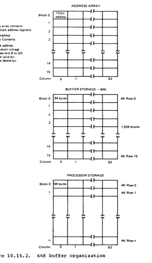
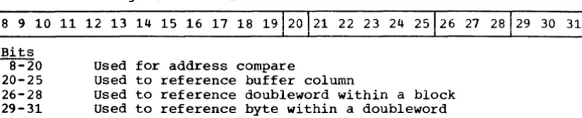
64K buffer organization • • • .•• .• .•• .• • .. • .• • Processor storage address format for buffer reference • • TLB format .•.• • .• .• • • .• .• • •
The 3036 Console .. ~ .. ~ • ~ ~ • ~ ~ .. .. ~
Control panel on the 3036 Console The operator frame • ,. .• • The program frame • • • •
The alter/display frame .• The configuration frame .• .• The system activity frame The TP link frame '. .• •
The normal 3036 Console configuration • .. • • • A maintenance mode 3036 Console configuration .• .• .• .• .• .. Director servicing using a maintenance mode console configuration • ,. • • • .• .• .• • .• it .. .. •• •
The 3033 Multiprocessor Complex .• , . . . .• ,. The normal console configuration for a 3033
6 8 11 19 20 28 30 31 33 50 53 61 62 63 63 65 61 70 73 14 81
Multiprocessor Complex .• .• .••• • • .• .• • .• ,. .• .• Components of the 3033 Attached Processor Complex .. The normal console configuration for the 3033
Attached Processor Complex • ,. • .•• .• • • • .••
86
• 109
• 115
TABLES (Sections 01 through 10)
... n. 4 1'\ 4
.LV, • .LV .• .L 10.15,.1 10,.20.1
40.10.1
3033 Processor machine check ~n'terrup't~ons • ,. .• .• • . • .22
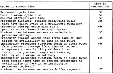
3033 Processor cycle and access times .• ,. . .• .• ,. ,. • .• • 26
Channel attachment and
uew
mode for the more frequentlyused I/O devices that attach to the 3033 Processor 40
Comparison of hardware features in the Model U
3033 Processor, Model A 3033 Processor, and
SECTION 01: HIGHLIGHTS OF THE 3033 PROCESSOR COMPLEX, ATTACHED PROCESSOR COMPLEX, AND MULTIPROCESSOR COMPLEX
The 3033 Processor Complex consists of the 3033 Processor, 3036 Console, and 3037 Power and Coolant Distribution Unit. The 3033
Processor is a high-speed, large-scale, advanced function processor of System/370. It has a significantly higher internal performance than System/370 Models 165 and 168. It offers these users new levels of price performance, new function, and improvements in availability and serviceability without the necessity of reprogramming. All but a few of the features for the 3033 Processor are standard.
The 3033 Processor is a general purpose processor and offers high performance for both commercial and scientific applications.. The 3033 Processor has hardware features and programming systems support, such as that for virtual storage and virtual machines, that are deSigned to facilitate application development and maintenance. In addition, a 3033 Processor Complex, its I/O devices, and its programming support can ease the expansion of data base and online data processing operations.
The 3033 Multiprocessor Complex is a tightly coupled multiprocessing configuration that consists of two 3033 Processors with multiprocessing hardware interconnected via the 3038 Multiprocessor Communication Unit, two 3036 Consoles, and two 3037 Power and Coolant Distribution Units.
The 3033 Attached Processor Complex is a tightly coupled
multiprocessing configuration that consists of a 3033 Processor with multiprocessing hardware interconnected to a 3042 Attached Processor via the 3038 Multiprocessor Communication Unit, two 3036 Consoles, and two 3037 Power and Coolant Distribution Units.. Like a 3033 Multiprocessor Complex, the attached processor configuration can execute two
instruction streams (tasks) simultaneously, one in each processor.
Highlights of the 3033 Processor Complex are as follows.
• The 3033 Processor is capable of an instruction rate generally in the range of 1.6 to 1.8 times the System/370 Model 168 Model 3 with identical programs and configurations running under OS/VS2 Release 3. The upper end of the range is identified by jobs generally of the commercial and interactive mix. The lower end of the range
represents an environment generally associated with scientific jobs, such as FORTRAN Compile and Go.
• The cycle time of the 3033 Processor is 57 nanoseconds.
• Basic control (BC) mode, for compatibility with System/360, and the System/370 extended control (EC) mode of processor operation are standard..
• The standard instruction set provides binary, decimal, and floating-point (including extended precision) arithmetic operations. It includes all the new System/370 instructions, that is, those
provided for System/370 but not System/360 (see section 10:05), as well as additional instructions that are part of the standard System/370 Extended Facility .•
• The System/370 Extended Facility is standard. It provides new function. When supported by the MVS/System Extensions program product, this facility provides the means to (1) help reduce the time needed to execute certain frequently used supervisor functions of MVS, (2) increase the efficiency of dynamic address translation, and (3) improve processor availability through additional protection of certain processor storage locations that are vital to operating system availability.
• separate instruction preprocessing and execution functions are implemented that provide overlap of instruction fetching,
instruction decoding, operand fetching, and instruction execution to
increase internal performance. A portion of the increased internal
performance of the 3033 Processor versus the 3168 Processing Unit is the result of several improvements in instruction preprocessing and execution function design.
• Dynamic address translation (OAT) is a standard facility that can be
made operative only when the 3033 Processor is operating in EC mode.
It provides hardware translation of addresses during program
execution. One virtual storage of up to 16 million bytes or
multiple virtual storages of up to 16 million bytes each can be
supported using DAT hardware. (The amount of virtual storage that
can be efficiently supported by a 3033 Processor depends on the
hardware configuration and job stream characteristics~)
• Channel indirect data addressing is a standard feature.. Channel
indirect data addressing enables the channels to access an I/O
buffer that is contained in noncontiguous processor storage areas
and is used when DAT mode is operative.
• An interval timer of 3.33 ms resolution and a time-of-day clock with a one-microsecond resolution are standard.
• A CPU timer and clock comparator are standard. The CPU timer
provides an interval timing capability similar to that of the interval timer but it is updated every microsecond, as is the
time-of-day clock. The clock comparator can be used to cause an
interruption when the time-of-day clock passes a specified value. These items provide higher resolution timing facilities than the interval timer and enable more efficient timing services routines to be written.
• Program event recording (PER) is standard and can be made operative
when the 3033 Processor is operating in EC mode. It is designed to
be used as a problem determination aid.. This feature includes
hardware that can monitor the following during program execution: successful branches, the alteration of general registers, and instruction fetches from, and alterations of, specified areas of processor storage.
• A monitoring feature is standard and can be used to trace user-defined program events for the purpose of debugging or statistics
gathering~
• The standard byte-oriented operands facility permits byte boundary alignment of the operands of nonprivileged instructions, making it unnecessary to add padding bytes within records or to blocked records for the purpose of aligning fixed- or floating-point data. Performance degradation for instructions that use unaligned data is greatly reduced in the 3033 Processor, when compared with the
degradation that occurs in a Model 168, as a result of instruction
preprocessing and execution function design changes. Only minimal
degradation occurs in the 3033 Processor.
• Reloadable control storage is included in the 3033 Processor to contain the microcode for the instruction set and, during servicing
operations, to contain fault locating microdiagnostics. Separate
reloadable control storage is provided for the microcode for the channels.
• storage features of the 3033 Processor are as follows:
A two-level storage system, consisting of fast, large-size processor (main) 5~orage used as backing storage for a smaller, high-speed buffer storage, is implemented .•
64K bytes of monolithic buffer storage with a 57-nanosecond cycle time are provided. The instruction processor function can fetch eight bytes from the buffer in 114 nanoseconds.
Processor storage sizes of 4M-, 8M-, 12M-, and 16M-bytes (M=1,048,516) are available. Processor storage is eight-way, doubleword interleaved and has a read/write cycle time of 285 nanoseconds for a doubleword. It is implemented using monolithic technology. store and fetch protection are standard .•
Error checking and correction (ECC) hardware that automatically corrects all single-bit processor storage errors and detects all double-bit and many multiple-bit errors is standard. More multiple-bit errors are detected in the 3033 Processor than in the Model 168 as a result of the implementation of a new ECC code.
• Channel features and I/O devices for the 3033 Processor are as follows:
Channels are packaged in groups and each group is controlled by a microprogrammed director. Channels are contained within the 3033 Processor but each channel group and its director has its own control storage, microprogram, and arithmetic logic unit so that channel operations interfere with instruction processing operations only when a channel and the instruction processor need access the same logical storage element simultaneously. A channel group can be serviced concurrently with normal processing and can be powered on and off separately from other channel groups and processor components.
Two channel groups, each of which consists of one byte multiplexer and five block multiplexer channels, are standard. Optionally, one additional channel group consisting of four block multiplexer
channels or one byte and three block multiplexer channels can be installed for a total of 16 channels in the processor. A block multiplexer channel can operate at a data rate of UP to 1.5
megabytes per sec (MB/sec). The five block multiplexer channels in a group are capable of achieving an aggregate data rate of 6.1 MB/sec when certain configuring rules are observed.
The optional TWo-Byte Interface feature can be installed on the first block multiplexer channel in each channel group to increase its maximum data rate to up to 3 MB/sec.. Optionally, one or two Channel-to-Channel Adapters can be installed in a 3033 Processor, one in each standard channel group.
Channel retry data is provided after channel errors so that error recovery routines can retry I/O operations. Significantly more logout data is provided after certain channel errors than for most other System/370 processors.
Most I/O devices that attach to the channels for a 3168 Processing Unit can be attached to the channels in a 3033 Processor.
• Space requirements for a 3033 configuration are significantly less than for a Model 168 configuration, since channels are contained within the 3033 Processor. In addition, the 3033 Processor requires less power, air cooling, and water cooling than a 3168 processing Unit with its standalone channels because of the new channel design and new technology for logic and processor storage.
• The console for the 3033 Processor is the standalone 3036 Console, which provides significant new operational and servicing
capabilities.
The 3036 Console provides the means for manually controlling 3033 Processor operations, controlling power on and off operations for processor complex components and subcomponents, loading microcode and microdiagnostics, configuring certain 3033 and 3036 components, and performing many diagnostic procedures,.
The 3036 Console contains two physically and functionally separate, individually addressable operating stations. Each station contains a CRT display and keyboard, diskette drive for loading microcode and microdiagnostics, and microprogram-controlled console processor that controls the operation of the station. Either station can be used to control normal processing operations while the other is used for service support operations. Alternatively, both stations can be used for normal processing operations or service operations.
The dual station design permits one of several types of maintenance operations, including one remote diagnostic procedure, to be
performed concurrently with normal processing operations. This dual station design also provides console backup.
Highlights of the 3033 Multiprocessor Complex are as follows:
• The IBM 3033 Multiprocessor Complex is capable of an instruction execution rate generally in the range of 1,.6 to 1.8 times that of the 3033 uniprocessor with similar configurations and identical programs running under OS/VS2 MVS,.
• All standard and optional features that are available for the 3033 Processor Complex are available for the 3033 Multiprocessor Complex.
• The features of the 3033 Multiprocessor Complex provide the
advantages normally provided by a tightly coupled multiprocessing as compared with two uncoupled uniprocessor configurations: improved availability, less complex operational requirements, improved resource utilization, operational flexibility, improved growth options, and improved throughput possibilities.
• The design of the multiprocessing capability for a 3033 Multiprocessor Complex provides advantages over a Model 168
Multiprocessing System, such as enhanced channel recovery hardware for use after an unrecoverable processor failure, a more convenient configuration capability via elimination of a configuration control panel, and serviceability improvements (as for a uniprocessor
configuration) provided by the 3036 Console.
Highlights of the 3033 Attached Processor Complex are as follows:
• The 3033 attached processor configuration contains two tightly coupled processors that are equivalent in function to the 3033 Processor for uniprocessor 3033 configurations except for the absence of ariy processor storage and channels in the 3042 Attached Processor. The 3033 and 3042, operating under the control of a single multiprocessing operating system, share all processor storage in the 3033 Processor and all I/O operations are performed by the 3033,.
• The 3033 Attached Processor Complex offers increased internal performance over a 3033 Processor Complex and provides advantages over two uniprocessor 3033 configurations, such as a single system image and improved resource utilization,.
Basic support of the 3033 Processor Complex is provided by the following system control programs: OS/VS1, OS/VS2 MVS and SVS, and VM/310.. The increased internal performance achieved when using these programming systems on a 3033 Processor versus a Model 168 can be of particular aid in expanding data base and online applications.
Support of the new function of the 3033 Processor, the System/370 Extended Facility, is provided by the MVS/System Extensions program product, which also offers several other performance enhancements for MVS users. The faster internal performance of the 3033 Processor and its large processor storage sizes combined with the support provided by MVS/System Extensions enables a 3033 installation to better utilize the benefits of MVS,.
The VM/System Extensions program product is designed to improve the performance of VM/370 through the utilization of a resource manager, increase the performance of virtual machines in which a virtual storage programming system is executing, support an MVS operating system with the MVS/System Extensions program product installed executing in a virtual machine, and provide other new functions. The ViM/Basic system Extensions program product provides a subset of the new functions offered by VM/System Extensions.
Tightly coupled multiprocessing support for the 3033 Multiprocessor Complex is provided by OS/VS2 MVS. The System/370 Extended Facility can be utilized in both processors during multiprocessor mode operations when the MVS/System Extensions' program product is installed.
Tightly coupled multiprocessing support for the 3033 Attached
Processor Complex is provided by OS/VS2 MVS and VM/370. The MVS/System Extensions program product supports the use of the System/370 Extended Facility in both the 3033 and 3042 during multiprocessing operations,. VM/370 with the VM/System Extensions program product installed supports operation of MVS/System Extensions during multiprocessing operations.
SECTION 05: 3033 PROCESSOR COMPLEX PHYSICAL COMPONENTS AND TECHNOLOGY
PHYSICAL COMPONENTS
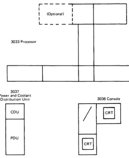
The major physical components of a 3033 Processor Complex are shown in Figure 05,.1. This uniprocessor configuration consists of a (1) 3033
Processor that contains monolithic processor storage and the channel groups, (2) standalone 3036 Console, and (3) standalone 3037 Power and Coolant Distribution Unit. A static converter or motor generator set is required to supply power for the components of the 3033 Processor
Complex.. A motor generator set is recommended .•
3033 Processor
3037 Power and Coolant
Distribution Unit
CDU
PDU
r -I
I (Optional)
I
L _ _ _ _
I
I
I I
3036 Console
/
I
CRTI
[image:13.615.41.294.251.560.2]ICRTI
Figure 05 .• 1.. Major components of the 3033 processor Complex
The size of uniprocessor models of the 3033 Processor is the same regardless of the amount of processor storage installed. A 3033
Processor that contains twelve channels does not contain the frame drawn wi th dotted lines in Figure 05.1,. The additional frame is required when the optional third channel group is installed. The size of the 3033
Processor without the optional channel group and director installed is only one frame larger than the 3168 Processing Unit, which does not contain any channels~
same as for the 3066 System Console and 3067 Power and Coolant
Distribution Unit for the 3168 processing Unit. Thus, space
requirements for a 3033 Processor Complex are significantly less than those for a Model 168 configuration with its standalone channels.
MOTOR GENERATOR SET
A motor generator (MG) set is the converter unit that provides the
power required by the components of the 3033 Processor Complex. It
takes 60 Hz (cycle) power from the building electrical distribution system, converts it to 415 Hz power, and supplies it to the PDU, from which it is distributed to the other components under control of the 3036 Console.
The MG set should be ordered at the same time as the 3033 Processor
Complex, with delivery up to two months prior to installation. While
IBM does not manufacture MG sets, a procedure is established for
ordering the required MG set through IBM. The same types of MG sets
that are used for a Model 168 system and 3032 Processor Complex can be
used for a 3033 Processor Complex. Note however, that the 3033
Processor requires approximately 33% less power than the 3168 processing
Unit.. (See IBM System/370 Installation Manual - Physical Planning,
GC22-7004, for more details concerning MG set size and installation requirements.)
COOLING
The heat generated by the logic boards in the 3033 Processor is
removed by forced air and a closed-loop water circulation system. A
liquid coolant is used in addition to air because of the amount of heat
generated by the densely packed circuits in the 3033 Processor. The
combined air and water cooling requirement for a 3033 Processor is approximately 201 less than for the 3168 processing Unit.
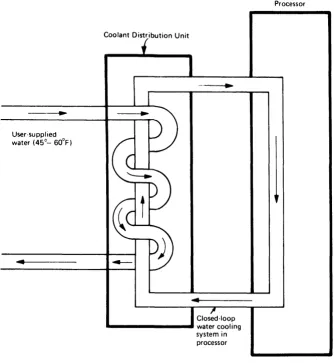
The installation must supply 28 gallons of cooled water per minute
(450 to 600 F .• ) to the coolant distribution unit (CDU), which is housed
in the standalone 3037 Power and Coolant Distribution Unit that also
contains power and the power distribution unit. Water is supplied to
the CDU in pipes under the raised floor. The chilled water entering the
CDU is used to control the temperature of the internal water that passes
through the 3033 Processor. That is, the user-supplied water does not
enter the closed-loop system of the 3033 Processor (see Figure 05 .• 2). The CDU houses the necessary controls to maintain the proper temperature
in the closed-loop system. An automatic valve adjusts the flow of
chilled water supplied to the CDU.
The use of water as the cooling liquid offers several advantages.
First, i t is readily available. The chilled water normally supplied for
air conditioning is acceptable. Second, water offers safety features.
Low pressure is required and the cooling system can operate at room
temperature, thereby eliminating problems with condensation. Last, a
simplified circulation system suffices, with relatively few moving parts
and less exposure to leaks. Pipe components within the 3033 Processor
are separated easily, and the valved connections close off automatically to prevent water from escaping.
Physical planning for 3033 Processor installation should ensure that
arrangements are made to provide the required water. (See IBM
System/370 Installation Manual - Physical Planning, GC22-7004-5, for more details .• ) Note that the water cooling system used and physical requirements for installation-supplied cooled water for the 3033
Processor are the same as those for a 3032 Processor and 3168 Processing
unit except for a slight difference in the amount of -cooled water that must be supplied.
User-supplied
water (45°- 60°F)
Coolant Distribution Unit
Closed-loop ... - - - -.... water cooling
system in processor
Processor
Figure 05,.2,. Conceptual flow of the water cooling system in the 3033 Processor
TECHNOLOGY
Monolithic technology is used to implement nearly all logic and all storage (processor, local, reloadable control, and buffer) in the 3033 Processor. Certain components of the 3033 Processor are implemented in a type of technology not used in the Model 168 Model 3 or other
System/370 processors. Specifically, technology that is not used in other System/370 processors is used for all logic in the instruction processor function (but not channel g~oups) in the 3033 Processor. This logic technology is faster and three times more dense than the MST used for logic in the Model 168 Model 3. It accounts for the faster cycle time of the 3033 Processor and also results in reduced space
requirements,.
[image:15.613.30.364.114.476.2]Different technology from that used in the Model 168 Model 3 is also used for the high-speed buffer and control storage of the 3033
Processor,. This technology is faster and denser than that used in the Model 168 Model 3 high-speed buffer and control storage and enables the 64K buffer in the 3033 Processor to be implemented in the same amount of space as the 32K buffer for the Model 168 Model 3. In addition, the TLB, high-speed buffer index array, and trace buffer in the 3033
Processor are implemented in a technology that is the same density but three times faster than that used in the same components in the Model 168 Model 3,.
The storage chip used for processor storage in 3033 Processors with 12M- or 16M-bytes contains twice the number of bits, 4K instead of 2K, as the storage chip used in most other System/370 processors and in 3033 Processors with 6M-bytes. (A 3033 Processor with 4M- or 8M-bytes may contain 2K or 4K chips in its processor storage, depending on its
shipment date.) This double density enables a 3033 Processor to contain 16M-bytes of processor storage in the same amount of space as would be required for 8M-bytes using the 2K-pit chip.
SECTION 10: 3033 PROCESSOR COMPLEX ARCHITECTURE DESIGN AND FUNCTIONAL COMPONENTS
10~05 ARCHITECTURE DESIGN AND PROCESSOR ELEMENTS
ARCHITECTURE DESIGN
Both basic control (BC) mode and extended control (EC) mode are
standard in the 3033 Processor. Thus, like other System/370 processors, the 3033 Processor is upward compatible with System/360 when BC mode is used.. The 3033 Processor is also upward compatible with other
System/370 processors for both BC and EC mode operations .•
As a result of the architecture design of the 3033 processor, BC or
Be mode programs written for other System/370 processors will run without modification on a 3033 Processor with a comparable hardware configuration, with the following exceptions:
1. Time-dependent programs. (They mayor may not execute correctly .• )
2. Programs that depend on the validity of storage data after system power has been turned off and then on .•
3. programs that use processor-dependent data such as that which is logged in the processor-dependent logout area.
4. Programs that depend on the nonusable lower processor storage area being smaller than 1928 bytes. This area can be reduced to 512 bytes by moving the 1416-byte machine check extended logout area .•
5.. programs deliberately written to cause certain program checks .•
6.. programs that depend on devices or facilities not implemented in the 3033 Processor .•
7. Programs that use processor-dependent operations of the 3033 Processor that are not necessarily compatible with the same operations on other System/370 processors~
8. programs operating in a virtual storage environment using READ DIRECT or WRITE DIRECT instructions that specify a virtual
storage address that does not translate to the same real storage address,. These programs must execute in virtual=real mode or be modified to specify a virtual=real address in READ DIRECT and WRITE DIRECT instructions.. This restriction exists because in a processor with the System/370 Extended Facility installed, the addresses in READ DIRECT and WRITE DIRECT instructions are assumed to be real instead of virtual as in processors without the System/370 Extended Facility installed .•
User-written processing programs that operate in a System/360 model or Model 168 under OS MFT or MVT control and do not violate a
restriction can operate in a 3033 Processor under OS/VS1 or OS/VS2 SVS control with little or no modification, as discussed in the optional programming system supplements (Sections 90 and 100). Similarly, user-written processing programs operating under OS MVT can operate under OS/vS2 MVS with little or no modification.
User-written processing programs that operate under one of the
system/370 operating systems that support the 3033 Processor and do not violate a restriction can operate on the 3033 Processor without
modification using a release of the operating system that supports the 3033 Processor.
PROCESSOR ELEMENTS AND FEATURES
Processor Elements
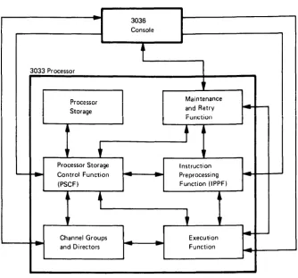
The major elements in the 3033 Processor and their interrelationships are shown in Figure 10,.05,.1,. Interaction of processor elements with the standalone console is also shown,. The major elements are:
• The instruction preprocessing function and execution function, which form the instruction processor function that executes the
instruction set for the 3033 Processor
• Processor storage
• The processor storage control function, which controls all access to processor storage by the other processor elements and the console and performs virtual-to-real address translation
• Two or three channel groups and their directors
• Maintenance and retry function
-
3036 Consolet
3033 Processor
•
I
ProcessorI
I
MaintenanceI I
I
StorageI
and Retry-
-
I I
l
Funciion~
t
r
Processor Storage I nstructi on
Control Function
--
-
-
Preprocessi ng-(PSCF) Function (lPPF)
.1'
,.
•
-Channel Groups Execution
--
-
and Directors-
..
-
Function-Figure 10,.05.1,. Major elements in the 3033 Processor
Processor Features
The standard and optional features for the 3033 Processor are listed
below,. The items not generally available for other System/370
processors or those whose implementation in the 3033 Processor differs
from that in the 3168 processing unit are identified by an asterisk and
discussed in this publication.. Items not identified by an asterisk
operate in the 3033 processor in the same manner as in other System/370 processors (see! Guide to the IBM system/370 Model 168 for System/360
~ (GC20-1787) or other appropriate guide series publications).
Standard features for the 3033 Processor are:
• BC and EC mode of operation and control registers
• Instruction set that includes binary, decimal, floating-point, and
extended precision floating-point arithmetic. Standard System/370
instructions for the 3033 Processor not provided for System/360 are:
CLEAR CHANNEL* CLEAR I/O
COMPARE AND SWAP
COMPARE DOUBLE AND SWAP
COMPARE LOGICAL CHARACTERS UNDER MASK COMPARE LOGICAL LONG
INSERT CHARACTERS UNDER MASK INSERT PSW KEY
[image:19.615.150.484.103.414.2]LOAD CONTROL LOAD REAL ADDRESS MONITOR CALL MOVE LONG PURGE TLB
RESET REFERENCE BIT SET CLOCK
SET CLOCK COMPARATOR SET CPU TIMER
SET PSW KEY FROM ADDRESS SHIFT AND ROUND DECIMAL START I/O FAST RELEASE STORE CHANNEL ID
STORE CHARACTERS UNDER MASK STORE CLOCK
STORE CLOCK COMPARATOR STORE CONTROL
STORE CPU ID STORE CPU TIMER
STORE THEN AND SYSTEM MASK STORE THEN OR SYSTEM MASK TEST PROTECTION.
MVS-dependent instructions.
• Dynamic Address Translation (includes translator, TLB., and STo-stack.) • Reference and Change Recording
• System/370 Extended Facility. • Instruction retry.
• Interval timer (3.3 ms resolution) • Time-of-day clock
• Clock comparator and CPU timer • Monitoring feature
• Program Event Recording
• Program interruption for SSM instruction • Expanded machine check interruption class. • ECC on processor storage.
• Byte-oriented operands • Store and fetch protection
• High-speed buffer storage - 64K bytes.
• Two channel groups, each with six channels (one byte and five block multiplexer).
• Channel Indirect Data Addressing
• Limited channel logout area with I/O retry data and an extended channel logout.
• Reloadable control storage for the execution function and channel groups
• Store status function • Direct Control
Optional features for the 3033 processor, which can be field installed, are:
• Channel-to-Channel Adapter (one in the first group and one in the second channel group)
• Extended Channels (third channel group and director with channels 12 through 15).
• TWO-Byte Interface (for block multiplexer channels 1, 7, and 12 or 13 only)
System/370 Extended Facility
The System/370 Extended Facility provides several extensions to
System/370 architecture: (1) low address protection, (2) the TEST
PROTECTION (TSPT) instruction, (3) the INVALIDATE PAGE TABLE ENTRY
(IPTE) instruction, (4) the common segment facility, (5) MVS-dependent instructions, and (6) virtual machine extended facility assist~
The IPTE instruction and COmmon segment facility are designed to increase the efficiency of dynamic address translation. They are discussed in section 10:15.
Low-Address Protection. The low address protection facility is enabled and disabled using bit 3 in control register o~ When enabled, this facility prevents all instructions from storing using addresses in the range of 0 through 511. Checking for the 0 through 511 range is performed before dynamic address translation is performed (if DAT is enabled). A protection program interruption occurs if a store attempt is made in the 0 through 511 address range and execution of the
instruction is terminated.
-Low-address protection can be used to provide protection against the destruction of data in low processor storage by programs that operate with storage protect key zero,. Thus, failures that occur because of inadvertent modifications to locations 0 to 511 are prevented.
Low address protection is applied to the store accesses made by all instructions to addresses 0 to 511 plus the store accesses to the oper ands of INVALIDATE PAGE TABLE ENTRY and READ DIRECT instructions,. Note that when enabled, low-address protection is not applied to store accesses made by the instruction processor or a channel during the following: interruption processing, interval timer updating, machine check and channel logouts, CSW storing during an I/O interruption or after I/O instruction execution, STORE CHANNEL ID instruction
processing, IPL processing, Or store status processing. It also is not applied to the data stores made by a channel during read I/O operations.
TEST PROTECTION Instruction.. The TEST PROTECTION privileged
instruction provides a programmed means of testing for the protection exceptions that will occur if a given real storage location is
referenced using the specified storage protect Key. The condition code is set to indicate that both fetching from' and storing in the location are permitted, only fetching is permitted, or neither fetching nor storing operations are permitted.
This instruction is designed to improve processor performance by eliminating the initialization and termination procedures normally required before a control program tests for potential protection violations before performing service for a processing program,.
The TEST PROTECTION instruction specifies the storage location to be tested (a virtual or real address) and the four-bit storage protect key to be used to determine whether storing is allowed. The store protect key in the instruction is compared with the protect key associated with the specified storage location. If they match, storing is permitted unless disallowed by the low address protection facility (that is, low address protection is enabled and the specified address is less than 512, before translation if it is a virtual address). The fetch protect bit in the key associated with the specified address is inspected to determine whether fetching is permitted.
MVS-Dependent Instructions,. Twelve privileged instructions that depend upon the conventions, fields, and control block formats of MVS for proper execution are provided to increase MVS performance. These instructions are the following:
• TRACE SVC INTERRUPTION • TRACE PROGRAM INTERRUPTION • TRACE INITIAL SRB DISPATCH • TRACE I/O INTERRUPTION • TRACE TASK DISPATCH • TRACE SVC RETURN • FIX PAGE
• SVC ASSIST
Virtual Machine Extended Facility Assist. This assist is designed to improve the performance of virtual machines in which MVS is being used by enabling the system/370 Extended Facility to be utilized in the virtual machine also. This assist enables the twelve MVS-dependent
instructions to be executed directly by a virtual machine without an interruption and simulation by CP. This assist is enabled when bit 1 in control register 6 is zero and bit 29 in this register is one. The virtual machine assist and virtual machine extended facility assist can be enabled simultaneously,.
10:10 INS!RUCTION PREPROCESSING AND EXECUTION FUNCTIONS
The 3033 Processor has a 57-nanosecond cycle time and an eight-byte-wide data path. Extensive parity checking is performed in the 3033 Processor to ensure the validity of the data being used. All data transfer, logical, and arithmetic operations are parity checked,.
Automatic hardware retry of most failing instruction operations, without programming assistance, is provided as an availability feature,.
INSTRUCTION PREPROCESSING FUNCTION
The 3033 Processor contains an instruction preprocessing function and an execution function that overlap instruction fetching and preparation with instruction execution to improve performance. The instruction preprocessing function is totally controlled by logic circuits and, therefore, can process several instructions concurrently while the execution function is executing a single instruction. Imprecise interruptions do not occur in a 3033 Processor.
The instruction preprocessing function (IPPF) prefetches instructions (maintaining them in sequence), decodes instructions, calculates
addresses, prefetches instruction operands, makes estimates of the success of conditional branches, and maintains three instruction streams,.
When a conditional branch is encountered, the instructions
immediately following the branch and those located at the branch address are prefetched and placed in separate instruction buffers within the instruction preprocessing function. This ensures the availability of prefetched instructions whether the branch is taken or not.
The IPPF contains three sets of instruction buffers each with four doublewords to hold prefetched non-decoded instructions, one instruction register to hold one instruction during its decoding, four instruction queuing registers to hold four decoded instructions until they are transferred to the execution function, a 24-bit adder that can accept three inputs and perform address calculation while decoding occurs, six operand address registers to retain calculated operand addresses for the execution unit, three instruction address registers (one for each
instruction stream), an address incrementer for incrementing and
decrementing addresses, and a length incrementer for computing the end-address of storage operands,. Assuming an average instruction size of four bytes, 24 instructions can be prefetched and held in the IPPF, of which up to four can be decoded,.
While the design of the instruction preprocessing function in the 3033 Processor is similar to that used in the instruction unit of the Model 168 processor, the instruction preprocessinq function in the 3033 Processor contains the following major enhancements that provide
increased internal performance over the Model 168:
• Three instruction streams of four doublewords are maintained instead of two instruction streams of two doublewords. This allows up to two branch instructions (instead of one as in the Model 168) to be processed concurrently.
• A copy of general registers 1 to 15 (contained in local storage) is maintained in the instruction preprocessing function to use for address calculations that are performed by the instruction preprocessing function. This enables instruction decoding and operand address generation for an instruction to be done in one cycle in the 3033 Processor while two are required in the Model 168.
• The 3033 Processor has six operand address registers and six
corresponding doubleword buffers, instead of two of each as in the Model 168. This substantially improves the ability of the IPPF to prefetch operands.
• The processing of CVD, CLC, MC, LM, STM, STNSM, STOSM, ICM, CLCM, STCM, STCTL, STIDP, SCK, SCKC, STCKC, SPT, STPT, STPX, and STAP instructions is overlapped with the processing of subsequent instructions in the 3033 Processor. Overlap of the following is disabled for only two cycles unless a word-overlap condition exists: MVN, MVC, MVZ, NC, OC, and
xc.
Overlap is disabled for all these instructions in the Model 168~• The execution of store type instructions is speeded up by the addition of certain registers. In the Model 168, there are two F-registers (for data storage) and each is associated with a specific operand address register. Only one register set can be used for an instruction. In the 3033 Processor, there are four F-registers and six operand address registers. There is no fixed relationship between a given F-register and address register and an instruction can utilize more than one register set. Thus, for example, an MVC instruction can store every other cycle and its execution improves by a factor of two to one. Execution of an STM instruction improves by a factor of four to one,.
• The IPPF obtains data not contained in the buffer faster than the instruction. unit in a Model 168. In the 3033 Processor, as each of the eight doublewords required to fill a buffer block are sent to the buffer, the IPPF can obtain the required doubleword(s) after the first without waiting for the entire buffer block to be loaded and then fetching the required doubleword(s), as is done in the Model 168. This particularly improves instruction fetching and the execution of an instruction that accesses more than one doubleword
eLM,
for example) .•• Significantly less performance degradation occurs in the 3033 Processor when byte-oriented operands are utilized because of changes in the way these operands are aligned (IPPF does aligning instead of a microprogammed routine in the execution function, for example) •
the index or base register in a successive instruction about to be decoded.
• Execution time for various instructions is reduced by one or more
cycles through various other setup changes in the IPPF.
The instruction preprocessing function in the 3033 Processor also contains an instruction pretest function like that in the instruction unit in a Model 168 for use in instruction nullification operations when
dynamic address translation is operative. In the 3033 Processor,
pretesting is performed by IPPF hardware and/or additional microcode
routines that are executed before normal instruction execution. However, for some instructions, prefetching of data accomplishes
pretesting so that no additional pretesting cycles are required.. A LOAD
instruction that addresses a word on a fullword boundary is an example of such an instruction.
EXECUTION FUNCTION
The execution function is predominantly microprogram controlled and
can execute one instruction at a time. It has the capability of
processing a new instruction every processor cycle and many instructions
(approximately half) can be executed in one cycle.. Emphasis is placed
on optimizing binary and floating-point arithmetic operations,. A 64-bit
parallel adder is used to perform binary and floating-point arithmetic, while an 8-bit serial adder is used in the execution of packed decimal arithmetic, as in the execution unit of the 3168 Processing Unit,.
The execution function in the 3033 Processor differs from the
execution unit in the 3168 Processing Unit in the following major areas:
• High-speed multiply, an optional feature for the Model 168 that provides faster execution of binary and floating-point arithmetic operations, is basic to the implementation of the execution
function.
• Storage-to-storage instruction overlap and general register manipulation is speeded up by the use of six doubleword operand buffers, instead of two as in the Model 168 execution unit,.
• More instructions require only a single execution cycle than in the Model 168 .•
• The processing of certain storage-to-storage format instructions, such as CLC, NC, OC, and XC, when the possibility of destructive
overlap does not exist, is faster,. In the 3033, the IPPF aligns
operands and the execution function uses the parallel adder to
process eight bytes at a time (in two cycles),. In the Model 168,
processing is done one byte per cycle.
• MVCL and CLCL instructions execute faster by processing eight bytes
per cycle, instead of eight bytes in four cycles. This enables more
data to be processed before execution of the instruction must be stopped to take an interruption and thereby reduces the amount of instruction stop and start-up processing.
• Execution time for ED and EDMK instructions is significantly
improved through the implementation of a new algorithm that requires more control storage.
• Execution time for other instructions, such as AP, SP, CP, and MVO is reduced through microprogram changes that require additional <70ntrol storage.
• Local storage is modified to permit an odd/even or even/odd general register pair to be read at a time, instead of one register at a time.
• Execution time for various other instructions is reduced by one or more cycles as a result of the improved setup implemented in the IPPF and/or changes in processing the instruction in the execution function.
Local storage contains the general and floating-point registers and has a read/write cycle time of 57 nanoseconds. It can be accessed by four sources and written into from one source in the same processor cycle,.
Control storage for the execution function consists of 4K words of monolithic reloadable control storage (RCS), with a 57-nanosecond cycle time. RCS can contain the entire instruction set for the 3033
Processor.
During a processor power-on or a processor initial microprogram load (IMPL) sequence, execution function RCS is automatically loaded with microcode from a removable diskette contained on a diskette drive in the 3036 Console,. See Section 20: 10 for a further discussion of
microprogram loading.
Instruction Retry
Detected hardware errors in the processor, except those that occur during execution of certain instructions that have passed beyond a threshold pOint, can be retried automatically by the instruction retry capabili ty of the execution function,. A mask bit (9) in control
register 14 (which controls the logging of retry data to the fixed
logout area) determines whether the processor is enabled or disabled for the instruction retry function.
If the processor is enabled for instruction retry, retry occurs after instruction errors, after failures that occur during interruption time when status information is being saved, after errors that occur during status saving for I/O instructions, etc. An I/O instruction, such as START I/O or TEST I/O, can be retried automatically by the hardware without an intervening I/O interruption if the instruction has not proceeded beyond an established threshold point,.
Instruction retry also occurs when an instruction error results from a buffer malfunction, if the instruction is a retryable type,. The buffer is bypassed while the instruction is retried so that processor storage is referenced directly,. If the retry is successful, operations continue as usual,.
xnstruction retry is accomplished by additional microprogram routines in the execution function and hardware included in the maintenance and retry function.. The failing processor operation is retried by the
microprogram up to seven times before it is determined that the error is uncorrectable. Most instructions must be completely reexecuted,.
Therefore, all data required for a retry is saved by the microprogram,. However, certain SS-format instructions are retried from the pOint of successful execution~ In this case, the microprogram saves the status data necessary to restart at the proper byte.
The following instructions cannot be retried in the 3033 Processor: DIAGNOSE, READ DIRECT, WRITE DIRECT, LOAD CONTROL, SET STORAGE KEY, RESET REFERENCE BIT, TEST AND SET, SET PREFIX, SIGNAL PROCESSOR,
an INSERT CHARACTERS UNDER MASK instruction that modifies the register used in calculating its operand address.
Two instruction retry mode control bits (which are set via a DIAGNOSE instruction) and a system recovery mask bit (4) in control register 14 determine whether a machine check interruption occurs after a successful instruction retry when the instruction retry facility is enabled. The retry mode control bits operate subject to the setting of the system recovery mask bit,. That is, the system recovery mask bit must be on as well when the mode control bits are set to recording mode in order for interruptions to occur after successful retr ies,.
InterruRtions
As in other System/370 processors, the implementation of the machine check class of interruption in the 3033 Processor is expanded
considerably from its implementation in System/360 in order to enhance system availability_ The other four interruption classes (I/O, SVC, program, and external) operate in the same manner in the 3033 Processor as in System/360 processors except for (1) additional program and
external interruptions that are defined for new features, (2) expansion of channel masking, and (3) expansion of external interruption masking to support new features.
~hen all interruption classes are enabled, the high-to-low priority for honoring requests is exigent (hard) machine check, program or SVC, repressible (soft) machine check, external, and I/O,.
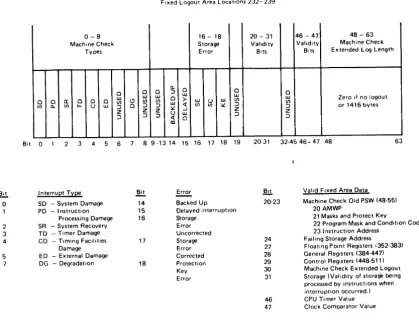
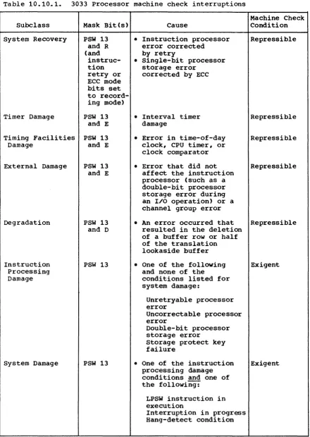
Machine Check Interruptions,. The 3033 Processor presents one of seven subclasses of machine check interruption, depending on the
specific processor malfunction,. Each interruption subclass is maskable and causes either a repressible machine check or an exigent machine check interruption (formerly called soft or hard machine check interruption, respectively) when enabled and a logout to the fixed processor storage area,.
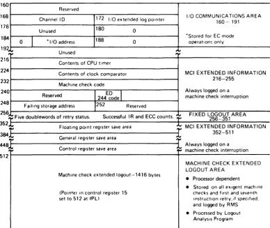
Fixed processor storage in the 3033 Processor consists of the fixed locations in decimal addresses 0-191, the fixed logout ~ in locations 256-351, the machine check interruption extended information in
locations 216-255 and 352-511, and the machine check extended logout area of 1416 bytes, which normally begins at location 512. Fixed locations 0-127 are identical in layout and content to these locations in other System/370 processors,. Figure 10.10,.1 shows the processor-dependent logout area for the 3033 Processor,.
A logout to the fixed locations, machine check interruption extended information area, and (if bit 9 in control register 14 is on) processor-dependent fixed logout area occurs when any type of machine check
interruption is taken. The data is processed by recovery management routines. The machine check interruption extended information area data indicates the reason for the interruption in the machine check code and contains the contents of the general, floating-point, and control
registers as well as CPU timer and clock comparator values.
The processor-dependent machine check extended logout area begins at the address specified in control register 15, which is set to decimal location 512 during IPL or system reset,. The save areas in the machine check extended logout area preserve the status of the processor at the time of the machine check interruption .•
The occurrence of a logout to the machine check extended logout area is controlled by the