Digital Equipment Corporation 1990.
This work may not be copied or reproduced in whole or in part for any commercial purpose. Permission to copy in whole or in part without any payment of fee is granted for nonprofit, educational, and research purposes provided that all such whole or partial copies include the following: a notice that such copying is by permission of the Systems Research Center of Digital Equipment Corporation in Palo Alto, California; an acknowledgement of the authors and individual contributors to the work; and all applicable portions of the copyright notice. Copying, reproducing, or republishing for any other purpose shall require a license with payment of fee to the Systems Research Center. All rights reserved.
Autonet:
a High-speed,
Self-configuring
Local Area Network
Using Point-to-point Links
MICHAEL D. SCHROEDER ANDREW D. BIRRELL MICHAEL BURROWS HAL MURRAY
ROGER M. NEEDHAM THOMAS L. RODEHEFFER EDWIN H. SATTERTHWAITE CHARLES P. THACKER
APRIL 21, 1990
ABSTRACT
Autonet is a self-configuring local area network composed of switches interconnected by 100 Mbit/second, full-duplex, point-to-point links. The switches contain 12 ports that are internally connected by a full crossbar. Switches use cut-through to achieve a packet forwarding latency as low as 2 microseconds per switch. Any switch port can be cabled to any other switch port or to a host network controller.
A processor in each switch monitors the network’s physical configuration. A distributed algorithm running on the switch processors computes the routes packets are to follow and fills in the packet forwarding table in each switch. This algorithm automatically recalculates the forwarding tables to incorporate repaired or new links and switches, and to bypass links and switches that have failed or been removed. Host network controllers have alternate ports to the network and fail over if the active port stops working.
With Autonet, distinct paths through the set of network links can carry packets in parallel. Thus, in a suitable physical configuration, many pairs of hosts can communicate simultaneously at full link bandwidth. The aggregate bandwidth of an Autonet can be increased by adding more links and switches. Each switch can handle up to 2 million packets/second. Coaxial links can span 100 meters and fiber links can span two kilometers.
CONTENTS
1. Introduction ...1
2. Overview...2
3. Design Decisions ...3
3.1 Point-to-Point Links at 100 Mbit/s ...3
3.2 Unconstrained Topology with Pre-calculated Packet Routes...3
3.3 Automatic Operation ...4
3.4 Crossbar Switches...4
3.5 Limited Buffering with Flow Control ...4
3.6 Deadlock-Free, Multipath Routing ...5
3.7 Short Addresses ...5
3.8 Hardware-Supported Broadcast...6
3.9 Alternate Host Ports ...6
3.10 Integrated Encryption ...7
3.11 Generic LAN Abstraction ...7
4. Innovations...7
4.1 Distributed Spanning Tree Algorithm with Termination Detection ...7
4.2 Up*/Down* Routing ...8
4.3 Dynamic Learning of Short Addresses...8
4.4 Automatic Reconfiguration ...8
4.5 First-Come, First-Considered Port Scheduler...9
5. Components ...9
5.1 Switch Hardware ...9
5.2 Controller Hardware... 11
5.3 Link Hardware ... 13
5.4 Switch Control Program ... 13
5.5 The SRC Service LAN ... 13
5.6 Host Software ... 14
6. Functions and Algorithms ... 15
6.1 Link Syntax... 15
6.2 Flow Control ... 16
6.3 Address Interpretation... 18
6.4 Scheduling Switch Ports ... 20
6.5 Port State Monitoring... 21
6.5.1 Port States ... 22
6.5.2 Hardware Port Status Indicators ... 22
6.5.3 Status Sampler ... 23
6.5.4 Connectivity Monitor ... 25
6.5.5 The Skeptics ... 25
6.6 Reconfiguration and Routing... 25
6.6.1 Spanning Tree Formation ... 26
6.6.2 Epochs ... 27
6.6.3 Assigning Short Addresses ... 28
6.6.4 Computing Packet Routes ... 28
6.6.6 Broadcast Routing and Broadcast Deadlock... 29
6.7 Debugging and Monitoring ... 30
6.8 A Generic LAN ... 31
6.8.1 Learning Short Addresses... 32
6.8.2 Bridging ... 33
6.8.3 Managing Alternate Links... 34
7. Conclusions and Future Work ... 35
Acknowledgements ... 37
1. INTRODUCTION
The Ethernet [10], with 10 Mbit/s host-to-host bandwidth and 10 Mbit/s aggregate bandwidth, has done well as the standard local area network (LAN) for high-performance workstations, but it is becoming a bottleneck in demanding applications. One modern workstation can use an Ethernet’s entire data transfer capacity, and workstations are getting faster and more numerous. There is an increasing need for a faster, higher-capacity LAN.
This need is being addressed commercially by the FDDI [4, 5] token ring LAN. With ten times greater host-to-host and aggregate bandwidth, FDDI will provide considerable relief for the Ethernet bottleneck. Autonet is an alternative approach to a higher-speed, higher-capacity, general-purpose LAN that could replace Ethernet. The fundamental advantage of Autonet over FDDI is greater aggregate bandwidth from the same link bandwidth. With FDDI the aggregate network bandwidth is limited to the link bandwidth; with Autonet the aggregate bandwidth can be many times the link bandwidth. Other advantages of Autonet over FDDI include lower latency, a more flexible approach to high availability, and a higher operational limit on the number of host that can be attached to a single LAN. Also, Autonet appears to be simpler than FDDI. There is no intrinsic reason why an Autonet should cost more than an FDDI ring.
Any replacement for Ethernet must retain Ethernet’s high availability and largely automatic operation, and be capable of efficiently supporting the protocols that work on Ethernet. Low latency is important in a new network because distributed computing makes request/response protocols such as RPC [9] as important as bulk-data transfer protocols. Because security will become increasingly important in the next decade, a new LAN must not hinder encrypted communication. Autonet addresses all these requirements. The primary goal of the Autonet project was to build an useful local area network, rather than to do research into component technologies for computer networks. Except in a few aspects, Autonet is designed using ideas that have been tried in other systems in different combinations. But bringing together just the right pieces can be a challenge in itself, and can produce a result that advances the state of the art.
Building Autonet required combining expertise in networking, hardware design, computer security, system software, distributed systems, proof of algorithms, performance modeling, and simulation. While a primary purpose for Autonet was to support for distributed computing, Autonet’s implementation uses distributed computing to perform its status monitoring and reconfiguration.
The development goal for Autonet was producing a network that would be put into service use. The prospect of service use forced us to develop practical solutions to both the big and the little problems encountered in the design process, and generated a strong preference for simplicity in the design. In early 1990 an Autonet replaced an Ethernet as the service LAN for our building, connecting over 100 computers. Service use is allowing the effectiveness of the design to be evaluated and the design to be improved based on operational experience.
host switch
link
controller
alternate
6 describes the operation of these components. Finally, section 7 discusses our early experience with Autonet and indicates directions for future work.
2. OVERVIEW
[image:6.612.171.439.282.499.2]An Autonet, such as the one illustrated in Figure 1, consists of a number of switches and host controllers connected by 100 Mbit/s full-duplex links. As shown by the grey arrows, a packet generated by a source host travels through one or more switches to reach a destination host. Switches contain logic to forward packets from an input port to one or more output ports, as directed by the destination address in each packet’s header. A non-blocking crossbar in each switch connects the input and output ports. Depending on the topology, the network can handle many packets at once. Packets even can flow simultaneously in opposite direction on a link.
Figure 1: A Portion of an Autonet Installation
Switches can be interconnected in an arbitrary topology, and this topology will change with time as new switches and links are added to the network, or as switches and links fail. A processor in each switch monitors the state of the network. Whenever the topology changes, all switch processors execute a distributed reconfiguration algorithm. This algorithm determines the new topology and loads the forwarding tables of each switch to route packets using all operational switches and links. In normal operation the switch processor does not participate in the forwarding of packets.
Hosts are connected to the Autonet via dual-ported controllers. For best network availability, a host is connected to two switches; the controller design allows only one of these connections to be used at a time. An Autonet ought to accomodate at least 1000 dual-connected hosts. Possible improvements to the reconfiguration algorithm would allow even larger Autonets.
3. DESIGN DECISIONS
This section summarizes the major decisions that characterize the Autonet design.
3.1 Point-to-Point Links at 100 Mbit/s
Ethernet uses a broadcast physical medium. Each packet sent on an Ethernet segment is seen by all hosts attached to the segment. As described by Tobagi [20], the minimum size of an Ethernet packet is determined by the need to detect collisions between packets. Reliable collision detection requires that each packet last a minimum time. At high bit rates this time translates into unacceptably large minimum packet sizes. Most 100 Mbit/s and faster networks, including Autonet, use point-to-point links to get away from these limitations. Using point-to-point links also can produce a design that is relatively independent of the specific link technology. As long as a link technology has the needed length, bandwidth, and latency characteristics, then it can be incorporated into the network with appropriate interface electronics.
We settled on 100 Mbit/s for the link bandwidth in Autonet because that speed represents a significant increase over Ethernet, while still being well within the limits of standard signalling technology. We chose the AMD TAXI chip set [3] to drive the links, leaving the subtleties of phase-locked loops and data encoding on the link to others. The overall Autonet design should scale to ten times faster links.
We engineered Autonet to tolerate transmission delays sufficient for fiber optic links up to 2 km in length. The first link we have implemented uses 75 ohm coaxial cable, with full-duplex signalling on a single cable. Electrical considerations limit these coax links to a maximum length of 100 m. If both link types were implemented they could be mixed in a single installation: coaxial links might be used within a building because of their lower cost; fiber optic links might be used between buildings because of their longer length limit.
3.2 Unconstrained Topology with Pre-calculated Packet Routes
An Autonet is physically built from multi-port switches interconnected by point-to-point links in an arbitrary topology (although the network will work better when thought is given to the topology). Any switch port can be cabled to any other switch port, or to a port on a host controller. A packet is routed from switch to switch to its destination according to pre-calculated forwarding tables that are tailored to the current physical configuration.
broken components. A ring topology like that used in FDDI has similar limitations. In addition, a ring has latency proportional to the number of hosts. A reasonably configured Autonet has latency proportional to the log of the number of switches. Autonet handles many packets simultaneously along different routes, has unconstrained topology, and allows a great deal of flexibility in establishing routes that avoid broken components.
3.3 Automatic Operation
One of the virtues of Ethernet and FDDI is that in normal operation no management is required to route packets. Even when multiple networks are interconnected with bridges [14], a distributed algorithm executed by the bridges determines a forwarding pattern to interconnect all segments without introducing loops. The bridge algorithm also automatically reconfigures the forwarding pattern to include new equipment and to avoid broken segments and bridges.
Autonet also operates automatically. This function is provided by software executing on the control processor in each switch that monitors the physical installation. Whenever a switch or link fails, is repaired, is added, or is removed, this software triggers a distributed reconfiguration algorithm. The algorithm adjusts the packet routes to make use of all operational links and switches and to avoid all broken ones. Of course, human network management is still required to repair broken equipment and adjust the physical installation to reflect substantially changed loads.
3.4 Crossbar Switches
An Autonet switch has 12 full-duplex ports that are internally interconnected by a crossbar. We chose a crossbar because its structure is simple and its performance is easy to understand, although a more sophisticated switch fabric could be used if it allowed a single input port to connect simultaneously to any set of output ports to support broadcast.
The small number of ports is a direct result of wanting to get the system into service quickly. All the Autonet hardware is built out of off-the-shelf components, and 12 ports was all that could be fit into a reasonably sized switch without using custom integrated circuits. The Autonet switch design would scale easily to 32 or 64 ports per switch by using higher levels of circuit integration. Such larger switches would be more cost-effective for all but the smallest installations, because fewer ports would be used for switch-to-switch links. A virtue of our small switch is that it generates a higher switch count, which in turn provides a more interesting test for the distributed reconfiguration algorithm.
3.5 Limited Buffering with Flow Control
FIFO to obtain deadlock-free routing for broadcast packets. The FIFO is only big enough to contain a few average-sized packets or less than one maximum-sized packet. Flow control is independent of packet boundaries so a single packet can be in several switches at once. A consequence of this scheme is that congestion can back up through the network, potentially delaying even packets that will not be routed over the congested link. Limited buffering also implies that a switch must be able to start forwarding a packet without having the entire packet in the local buffer. In fact, in Autonet such cut-through forwarding can begin after only 25 bytes have arrived.
An alternative buffering scheme would be to provide many packets of buffering at each receiving switch port, say using 1 Mbyte of memory, and to provide no flow control at this level. The port would have a higher capacity to absorb incoming traffic during periods of congestion, delaying the need to respond to the congestion and allowing time for congestion avoidance mechanisms to work. Also, longer links could be used because the absence of flow control eliminates the maximum link latency constraint. Eventually, though, a port would have to defend itself by discarding arriving packets.
We chose limited buffering with flow control because it uses less memory per switch port, making the switches simpler and smaller. In the absence of proven mechanisms for avoiding congestion, an additional advantage of our scheme may be that communication protocols will be more stable because the flow control scheme responds to link overload by backing up packets rather than by throwing them away.
3.6 Deadlock-Free, Multipath Routing
Because Autonet uses flow controlled FIFOs for buffering and does not discard packets in normal operation, deadlock is possible if packets are routed along arbitrary paths. Deadlocks can be dealt with by detecting and breaking them, or by avoiding them. For Autonet we chose the latter approach. Detecting deadlocks reliably and quickly is hard, and discarding an individual packet to break a deadlock complicates the switch hardware. Our scheme uses deadlock-free routes while still allowing packet transmission on all working links. (See section 4.2.) The scheme has the property that it allows multiple paths between a particular source and destination, and takes advantage of links installed as parallel trunks.
3.7 Short Addresses
The Autonet reconfiguration algorithm assigns a short address to each switch and host in the network. (A few short addresses are reserved for special purposes like broadcast.) Short addresses contain only enough bits (11 bits in the prototype) to name all switch ports in a maximal-sized Autonet. A forwarding table in each switch, indexed by a packet’s destination short address (and incoming port number), allows the switch to quickly pick a suitable link for the next step in a route to the packet’s destination. The forwarding table is constructed as part of the distributed configuration algorithm that runs whenever the physical installation changes, breaks, or is repaired. The short address of a switch or host can change when reconfiguration occurs, although it usually does not.
schemes, UID addressing is the most complex in a network that requires explicit routing, because the network must know a route to each UID-identified destination and do one or more UID-keyed lookups to forward a packet. Source routing removes from the network the responsibility for determining routes, placing it instead with the hosts in smart controllers or in system software. The network must contain mechanisms to report the physical configuration to the hosts and to alter packets as they are forwarded. Source routing eliminates the possibility of dynamic choice of alternative routes. In comparison, Autonet’s use of short addresses results in relatively simple switch hardware without giving up dynamic multipath routing.
When considering alternative addressing schemes for LANs we must keep in mind that Ethernet has established UID addressing as the standard interface for datagrams. What the network hardware does not provide, the host software must. So the design question becomes one of splitting the work of providing UID addressing between network switches, host controllers, and host software. For Autonet, all host controllers and switches have 48-bit UIDs; host software implements UID addressing based on Autonet short addresses. (See section 3.11.)
3.8 Hardware-Supported Broadcast
Because Ethernet naturally supports broadcast, high-level protocols have come to depend upon low-latency broadcast within a LAN. Autonet switch hardware can transmit a packet on multiple output ports simultaneously. This capability is used to implement LAN-wide broadcast with low latency by flooding broadcast packets on a spanning tree of links. Since a broadcast packet must go everywhere in a network, the aggregate broadcast bandwidth is limited to the link bandwidth. As we found out, supporting broadcast complicates the problem of providing deadlock-free routing. (See section 6.6.6.) Having low-latency broadcast, however, simplifies the problem of mapping destination UIDs to short addresses.
3.9 Alternate Host Ports
In an Autonet, a host is directly connected to an active switch. In an Ethernet-based extended LAN, a host is directly connected to a passive cable. An active switch has a greater tendency to fail than a passive cable. The specific availability goal for Autonet is that no failure of a single network component will disconnect any host. Thus, Autonet allows each host to be connected to two different switches. The mechanism we chose for dual connection is to provide two ports on an Autonet host controller. The host chooses and uses one of the ports, switching to the alternate port after accumulating some evidence that the chosen port is not working.
alternate ports is the increased cost of more host-to-switch links and extra switches. For 100 Mbit/s links, however, the cost per link is quite low compared to the cost of the host that typically would be connected to such a network.
3.10 Integrated Encryption
Security in most distributed systems must be based on encrypted communication. We wanted encrypted packets to be handled with the same latency and throughput as unencrypted ones -- secure communication is more likely to be used if there is no performance penalty. Therefore we have put a pipelined encryption chip in the host controller. This chip can encrypt and decrypt packets as they are sent or received with no increase in latency over unencrypted packets.
3.11 Generic LAN Abstraction
Because of short addresses, Autonet presents a different interface to host software than does Ethernet. When faced with the job of integrating Autonet into our operating system, we quickly decided that this difference should be hidden at a low level in the host software. The interface “LocalNet” makes available to higher-level software multiple generic LANs that carry Ethernet datagrams addressed by UID. Machinery inside LocalNet notices whether an Ethernet or an Autonet is being used. For packets transmitted over Autonet, LocalNet supplies the Autonet packet header complete with destination and source short addresses. LocalNet learns the correspondence between UIDs and short addresses by inspecting arriving packets.
4. INNOVATIONS
In a few areas the Autonet design appears to break new ground. We highlight these areas here. Later sections describe these features in more detail.
4.1 Distributed Spanning Tree Algorithm with Termination Detection
Deadlock-free routing and the flooding pattern for broadcast packets in Autonet are both based on identifying a spanning tree of operational links. The spanning tree is computed using a distributed algorithm similar to Perlman’s [16]. That algorithm has the property that all nodes will eventually agree on a unique spanning tree, but no node can ever be sure that the computation has finished. For Autonet, indefinite termination is unacceptable, because an Autonet cannot carry host traffic while reconfiguration is in progress. To do so would invite deadlock caused by inconsistent forwarding tables in the various switches.
4.2 Up*/Down* Routing
Deadlock-free routing in Autonet is based on a loop-free assignment of direction to the operational links. The basis of the assignment is the spanning tree described in the previous section, with “up” for each link being the end that is “closer” to the spanning tree root. The result of this assignment is that the directed links do not form loops. We define a legal route to be one that never uses a link in the “up” direction after it has used one in the “down” direction. This up*/down* routing guarantees the absence of deadlocks while still allowing all links to be used and all hosts to be reached.
4.3 Dynamic Learning of Short Addresses
The LocalNet layer of host software, mentioned above, is given UID-addressed packets to transmit over the network. If a packet is to be delivered over an Autonet then LocalNet must provide the complete Autonet packet header, including the short addresses of the source and destination.
LocalNet uses a UID-addressed cache for recording the short addresses corresponding to various destination UIDs. The information in this UID cache comes from inspecting the source short-address and source UID in each packet that is received. When the specific short address of a destination is not known, a packet is transmitted using the broadcast short address; the destination UID in the packet allows the intended target host to accept the packet and all other hosts to reject it. The next response from the destination allows LocalNet to learn the correct short address. If responses are not forthcoming, LocalNet also can request the short address of another host by using Autonet broadcast to contact the LocalNet implementation at that host. This scheme allows a host to track the short addresses of various destinations without generating many extra packets and without bothering higher layers of software. The learning algorithm requires only 15 extra instructions per packet received.
4.4 Automatic Reconfiguration
The Autonet reconfiguration mechanism is based on each switch monitoring the state of its ports. Hardware status indicators report illegal transmission codes, syntax errors, lack of progress, and other conditions for each port. As an end-to-end check, the switch control program verifies a good port by exchanging packets with the neighboring switch. The appearance or disappearance of a responding neighbor on some port will cause a switch to trigger a reconfiguration.
4.5 First-Come, First-Considered Port Scheduler
Packets arriving at an Autonet switch must in turn be forwarded to one or more output ports. (Packets destined for the control processor on the local switch are forwarded to a special internal port.) For packets to a single destination host, the switch determines a set of output ports by lookup in the forwarding table. Any port in the set can be used to send the packet. For broadcast packets the switch determines by lookup in the forwarding table the set of output ports that must forward the packet simultaneously. Scheduling the output ports to fulfill both sorts of requests must be done carefully to prevent starvation of particular input ports, which in turn could lead to performance anomalies including deadlocks.
An Autonet switch includes a strict first-come, first-considered scheduler that polls the availability of output ports and assigns them to the forwarding requests generated by the input ports. This scheduler, implemented in a single Xilinx programmable gate array [21], eliminates the problem of starvation and is a key element in achieving Autonet’s best-case switch transit latency of 2 µs (achieved when the router queue is empty and a suitable output port is available).
5. COMPONENTS
We begin a more detailed description of the Autonet design with an overview of the hardware and software components.
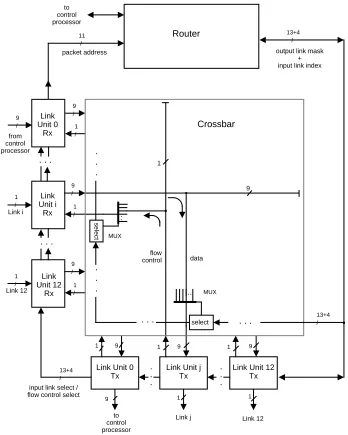
5.1 Switch Hardware
Figure 2 presents a block diagram of the Autonet switch. The switching element is a 13 by 13 crossbar constructed from paired 8-to-1 multiplexer chips. Twelve of the crossbar inputs and outputs are connected to link units that can terminate external links. The 13th input and output are connected via a special link unit to the switch’s control processor, so it can send and receive packets on the network. The crossbar provides a 9-bit data path from any input to any free output as well as a 1-bit path in the other direction. The former is used to forward packet data and the packet end marker; the latter to communicate a flow control signal. The crossbar also can connect a single input port to an arbitrary set of output ports.
The control processor is a Motorola 68000 [15] running on a 12.5 MHz clock. The processor uses 1 Mbyte of video RAM as both its main memory and its buffers for sending and receiving packets: the processor uses the random access ports to the memory while the crossbar uses the serial access ports. A 64-Kbyte ROM is available for booting the control processor at power-up. The processor has access to a timer that interrupts every 328 µs for calculating timeouts. Because of limited space on the board, however, no CRC or encryption hardware is provided. CRCs for packets to/from the control processor are checked/generated by software. Currently none of the packets sent or received by the control processor are encrypted. The control processor also has access to a ROM containing the switch’s 48-bit UID, and to red and green LEDs on the switch front panel.
.. MUX 9 / 1 / 9 / 1 / 1 / 1 / 1 9
1 9 1 9
Link Unit 0 Tx
Link Unit j Tx
Link Unit 12 Tx
Router
Link i
Link 12
9 1 1
to control processor
Link j Link 12
Link Unit 12 Rx Link Unit i Rx : data 9 1 packet address 11 / . . . . . .
output link mask + input link index
. . . . . . 13+4 / 13+4 /
input link select / flow control select
9 / 1 / 9 / from control processor Link Unit 0 Rx flow control Crossbar to control processor MUX . . . . . .
. . . 13+4/
select
select
. . .
[image:14.612.133.481.235.670.2]uses the AMD TAXI receiver to convert from the 100 Mbit/s serial data stream on the link to a 9-bit parallel format. The 9th bit distinguishes the 256 data byte values from 16 command values used for packet framing and flow control. The arriving data bytes (and packet end marks) are buffered in a 4096 by 9 bit FIFO. Logic at the output of the FIFO captures the address bytes from the beginning of an arriving packet and presents them to the switch’s router. Once the router has set up the crossbar to forward the packet, the link unit removes the packet bytes from the FIFO and presents them to the crossbar input. The flow control signal from the crossbar enables and disables the forwarding of packet bytes through the crossbar. As soon as a packet end command is removed from the FIFO and forwarded, the output port or ports become available for subsequent packets.
The transmit path in the link unit accepts parallel data from the crossbar and presents it to the AMD TAXI transmitter, which converts it to 100 Mbit/s serial form and sends it down the link. The receive and transmit portions of a single link unit are tied together so that the flow control state derived from the receiving FIFO can be transmitted back over the transmit channel on the same link. (See section 6.2.) A link unit does not include CRC hardware; an Autonet switch does not check or generate CRCs on forwarded packets. A link unit maintains a set of status bits that can be polled by the control processor. These status bits are a primary source of information for the algorithms that monitor the condition of the ports on a switch to decide when a network reconfiguration should occur. The control processor also has some control over the operation of an individual link unit. Via a control register each link unit can be instructed to illuminate LEDs on its front panel, to send special-purpose flow control directives, and to ignore received flow control.
The router contains 64 Kbytes of memory for the forwarding table and a routing engine that schedules the use of switch output ports. The forwarding tables are loaded by the control processor as part of a network reconfiguration. The routing engine is implemented in a single Xilinx 3090 programmable gate array.
Most of the switch operates on a single 80 ns clock. Link units can forward one byte of packet data into the crossbar on each clock cycle. The router can make a forwarding decision and set up a crossbar connection every 6 clock cycles, producing a packet forwarding rate of about 2 million packets per second. The latency from receiving the first bit of a packet on an input link to forwarding the first bit on an output link is 26 to 32 clock cycles if the output link and router are not busy.
The Autonet switch is packaged on 5 card types in a 45 x 18 x 30 cm Eurocard enclosure. A completely populated switch contains 12 link units, 5 2-bit crossbar slices, 1 control processor, and 1 router, all implemented on 10 x 16 cm cards. The backplane, into which all other card types plug at right angles, is a 43 x 13 cm board. A switch draws about 160 w of power.
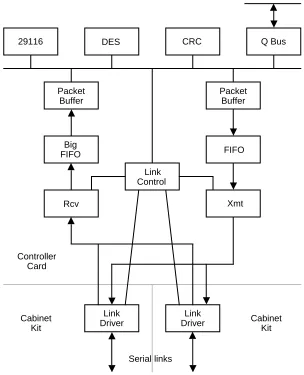
5.2 Controller Hardware
The first host controller for Autonet, shown in Figure 3, attaches to the Digital Equipment Corporation Q-bus [11] that is used in our Firefly [19] multiprocessor computers. In general, we believe that a network controller should be both simple and fast, and play no role in the correct operation of the network fabric. Operating at the full 100 Mbit/s network bandwidth with low latency requires a completely pipelined structure and packet cut-through for transmit and receive. Simplicity requires no higher-level protocol processing in the controller. In the case of this first controller, however, the 14 Mbit/s bandwidth of the Firefly Q-bus allows use of a shared data bus within the controller and elimination of cut-through with little impact on controller latency or throughput.
Q Bus CRC
DES 29116
Packet Buffer
Packet Buffer
Big
FIFO FIFO
Link Control
Rcv Xmt
Link Driver
Link Driver
Serial links
Cabinet Kit Cabinet
Kit Controller
[image:16.612.153.457.74.449.2]Card
Figure 3: Structure of the Q-bus Autonet Controller
The controller itself fills a 10.5 x 8.5 inch quad Q-bus card. The receive path is pipelined up to the point where arriving packets are stored in a 128-Kbyte receive buffer. The transmit path is pipelined outward from a 128-Kbyte transmit buffer. CRC checking and generation are done with a Xilinx 3020 [21]. Encryption is handled by an AMD 8068 encryption chip [2]. The connections between the transmit buffer, receive buffer, CRC chip, encryption chip, and Q-bus are via a 16-bit internal bus. The controller board includes a ROM containing a 48-bit UID that can be used as the host’s UID address.
5.3 Link Hardware
The first links implemented for Autonet use 75 ohm coaxial cable. A hybrid circuit allows both channels of a full-duplex link to be carried on a single cable. This implementation has the consequence that signals transmitted on an Autonet port can be reflected and correctly received at the same port. Reflection occurs when no cable is attached, when an unterminated cable is attached, and when the attached cable terminates at an unpowered remote port. Thus, a host or switch must be prepared to receive its own packets.
The circuit driving the links includes a high-pass filter that prevents frequencies below about 10 MHz from being transmitted. This filter is needed because the data encoding scheme used by the TAXIs allows signals with low frequency components to be generated by sending certain legal sequences of bytes and commands. Without the filter, low frequency transitions can prevent the receiver from recovering the data correctly.
The service network in our building uses Belden 82108 low-loss cable and standard cable television “F” connectors. We accept cabinet kits and link unit cards for service if a packet-echoing protocol can send and receive 40,000 packets of 1,500 bytes each over a 100-meter link between the test host and test switch without a CRC error.
5.4 Switch Control Program
Autopilot, the software that executes on the control processor of each switch, is responsible for implementing Autonet’s automatic operation. Its major functions are propagating and rebooting new versions of itself, responding to monitoring and debugging packets, monitoring the physical network, answering short-address request packets from attached hosts, triggering reconfigurations when the physical network changes, and executing the distributed reconfiguration algorithm.
The Autopilot source code consists of about 20,000 lines written in C and 3500 lines written in assembler. This generates a 62,000-byte object program. A stable version of Autopilot is included in the switch boot ROMs and is automatically loaded when power is turned on or the switch is reset. Whenever a new version is ready for use, it is down loaded from the programming environment (a Firefly workstation) over the Autonet itself into the nearest switch. The version of Autopilot running there accepts the new version, boots it, and then propagates it to neighboring switches.
The structure of Autopilot is typical of small, real-time, control programs. Interrupt routines enqueue and dequeue buffers for packets sent and received by the control processor. Everything else runs at process level as tasks under the control of a non-preemptive scheduler. Tasks are structured as procedure calls that run to completion within a few milliseconds. The task scheduler manages a timer queue for tasks that need to be run after a timeout has expired. Current timeout resolution is 1.2 milliseconds. The major algorithms in Autopilot are described in later sections.
5.5 The SRC Service LAN
GetInfo(net, info) SetState(net, state) Send(net, buffer, size) Receive(buffer, status) StartForwarding(net1, net2)
LocalNet UID Cache
to controller to controller
• • •
Ethernet Driver
Autonet Driver
With each host connected to two switches, this configuration has the capacity to attach 120 hosts. The Autonet is connected to the Ethernet in the building via a bridge. Thus the Autonet and Ethernet behave as a single extended LAN.
The hosts on Autonet are Firefly workstations and servers. A Firefly contains 4 CVax processors providing about 3 Mips each and can have up to 128 Mbytes of memory. Typical workstations have 32 or 64 Mbytes of memory. All processors see the same memory via consistent caches. At least until the Autonet proves itself to be stable and reliable, and the more disruptive experiments stop, most Fireflies are connected to both the Autonet and the Ethernet. The choice of which network to use can be changed while the system is running. Switching from one network to the other can be done in the middle of an RPC call or an IP connection without disrupting higher-level software.
5.6 Host Software
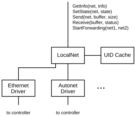
[image:18.612.194.415.376.567.2]The Firefly host software for Autonet includes a driver for the controller, the LocalNet generic LAN with UID cache, and the Autonet-to-Ethernet bridging software. This software is written in Modula 2+ [18] and executes in VAX kernel mode. The Firefly scheduler provides multiple threads [7, 8] per address space (including the kernel), and the Autonet host software is written as concurrent programs that execute simultaneously on multiple processors.
Figure 4: Structure of Low-level LAN Software for the Firefly
Usually many threads are blocked in Receive. Finally, the StartForwarding procedure causes the host to begin acting as a bridge between two networks.
For transmission on Autonet, the LocalNet UID cache provides the short address of a packet’s destination. This cache is kept up-to-date by observing the source UID and source short-address of all packets that arrive on the Autonet, and by occasionally requesting a short address from another LocalNet implementation using Autonet broadcast. (See section 6.8.1.) When a host is acting as an Autonet-to-Ethernet bridge, LocalNet observes the packets arriving on Ethernet as well, using the UID cache to record which hosts are reachable via the Ethernet. Thus, by looking up the destination UID of each packet that arrives on either network, LocalNet can determine whether the packet needs to be forwarded on the other network. (See section 6.8.2.)
6. FUNCTIONS AND ALGORITHMS
We now consider in more detail the major functions and algorithms of Autonet.
6.1 Link Syntax
The TAXI transmitter and receiver are able to communicate 16 command values that are distinct from the 256 data byte values. We use these commands to communicate flow control directives and packet framing. When a TAXI transmitter has no other data or command values to send, it automatically sends a sync command to maintain synchronization between the transmitter and receiver. Thus, one can think of the serial channel between a TAXI transmitter and receiver as carrying a continuous sequence of slots that can either be filled with data bytes or commands, or be empty.
In Autonet, flow control prevents a sender from overflowing the FIFO in the receiving switch. Autonet communicates flow control information by time multiplexing the slots on a channel. Every 256th slot is a flow control slot. The remaining slots are data slots. Normally start or stop directives occupy each flow control slot, independent of what is being communicated in the data slots. To make it easy for a switch to tell whether a link comes from another switch or from a host, host controllers send a host directive instead of start. Because flow control directives are assigned unique command values, they can be recognized even when they appear unexpectedly in a data slot. Thus, the flow control system is self-synchronizing. Flow control is discussed in more detail in the next section.
Two special-purpose flow control directives, idhy and panic, may also be sent.
Idhy, which stands for “I don’t hear you”, is sent on a switch-to-switch link when one
switch determines that the link is defective, to make sure the other switch declares the link to be defective as well. Panic is intended to be sent to force the other switch to reset its link unit, clearing the receive FIFO and reinitializing the link control hardware so reconfiguration packets can get through. We have not yet implemented the panic facilities.
crossbar DATA FLOW CTRL crossbar FIFO FIFO throttle MUX DMUX DMUX MUX TAXI Rx i TAXI Tx i TAXI Tx j TAXI Rx j half full clk mod 256
clk mod 256 send flow send flow data flow ctrl data + flow ctrl data + flow ctrl data + flow ctrl data + flow ctrl / 1 / 1 / 9 / 9 / 1 / 1 / 9 / 9 data flow ctrl data data flow ctrl data flow ctrl crossbar DATA FLOW CTRL crossbar FIFO FIFO throttle MUX DMUX DMUX MUX TAXI Rx i TAXI Tx i TAXI Tx j TAXI Rx j half full clk mod 256
clk mod 256 send flow send flow data flow ctrl data + flow ctrl data + flow ctrl / 1 / 1 / 9 / 9 / 1 / 1 / 9 / 9 data flow ctrl data data flow ctrl data flow ctrl Channel 1 Channel 2
bytes, so neither controllers nor switches may send sync commands within packets when flow is allowed. Thus, a link is never wasted by idling unnecessarily within a packet, and a link unit can assume that in normal operation packet bytes are available to retrieve from the FIFO. Between packets all data slots are filled with sync commands.
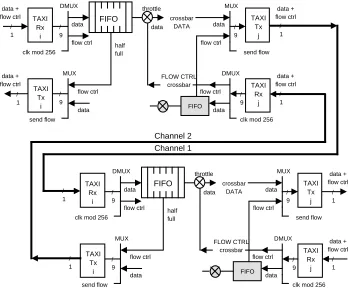
6.2 Flow Control
[image:20.612.132.480.350.638.2]Figure 5 illustrates the Autonet flow control mechanism. The figure contains pieces of two switches and a link between them. The names “channel 1” and “channel 2” refer to the two unidirectional channels on the link. In the receiving link unit of channel 1, a status signal from the FIFO chip indicates whether the FIFO is more or less than half full. This information determines the flow control directives being sent on channel 2, the reverse channel of the same link. When a flow control slot occurs, a start command is sent if the receiving FIFO is less than half full; stop is sent if it is more than half full. Back at the receiving link unit of channel 2, the flow control directives generate a flow control signal for the crossbar. If the output port is forwarding a packet, then the flow control signal uses the 1-bit reverse path through the crossbar to open and close the throttle on the FIFO that is the source of the packet.
Figure 5: Switch-to-switch Flow Control Mechanism
receiving no flow control usually means that the other end of the link is connected to an alternate host port. Receiving no flow control commands should cause a link control unit to act as though host (or start if that directive has been received more recently than
host) is being received, thus allowing packets to be forwarded on such a link, effectively
discarding them. Due to an oversight in the design, however, link units that are receiving no flow control keep acting on the last flow control directive received. The last directive could have been stop; it is unpredictable following switch power up. Switch software detects and clears the backups that can result from such indefinite cessation of flow.
This flow control scheme can cause congestion to back up across several links. Consider a sequence of switches ABCD along the path of some packet. If the receiving FIFO in C issues stop, say because the CD link is not available at the moment, then the FIFO in B will stop emptying. Packet bytes arriving from A will start accumulating in B’s FIFO and eventually B will have to issue stop to A. Thus congestion can back up through the network until the source controller is issued a stop. If the congestion persists long enough, then the network software on the host would stop sending packets; threads making calls to transmit packets would delay returning until more packets could be sent.
Autonet host controllers may not send stop commands. Thus, a slow or overloaded host cannot cause congestion to back up into the network. A slow host should have enough buffering in its controller to cover the bursts of packets that will be generated by the communication protocols being used. A controller will discard received packets when its buffers fill up.
We can now understand the relationship between FIFO length, the frequency of flow control slots, and link latency. Assume that the FIFO holds N bytes and that it issues
stop whenever the FIFO contains more than (1 - f) N bytes, where 0 < f ≤ 1. A flow
control command is sent every S slots. Assume that the link latency is W slot transmission times. In the worst case the receiving FIFO is not being emptied and the transmitter sends bytes continuously unless stopped. At the time the receiver causes a
stop command to be sent, its FIFO may contain as many as (1 - f) N + (S - 1) bytes.
Another 2 W bytes will arrive at the FIFO before the stop is effective, assuming the transmitter acts on the received stop with no delay. To prevent the FIFO from overflowing then, it must be that:
N ≥ (1 - f) N + (S - 1) + 2 W
From the speed of light, the velocity factor of fiber optic cable (which is a bit slower than coaxial cable), and a slot transmission time of 80 ns we can compute that W = 64.1 L, where L is the cable length in kilometers. Thus:
N ≥ (S - 1 + 128.2 L) / f
For S = 256 slots, f = 0.5, and L = 2 km, we see that N must be 1024 bytes.
Address Bytes Arriving Packet
Incoming Link #
B = and/or Link Vector Forwarding Table
01234 . . . FIFO
only between packets. For this case, we can calculate the maximum allowable broadcast packet length as the FIFO size minus the worst case count of bytes already in the FIFO when the first byte of the broadcast packet arrives. Thus:
B ≤ N - (1 - f) N - (S - 1) - 128.2 L
So, taking B into account, the size needed for the FIFO becomes: N ≥ (B + S - 1 + 128.2 L) / f
The minimum acceptable value for B is about 1550 bytes. This size allows Autonet to broadcast the maximum-sized Ethernet packet with an Autonet header prepended. The corresponding N is about 4096 bytes. This increase in FIFO size is one of the costs of supporting low-latency broadcast in Autonet.
6.3 Address Interpretation
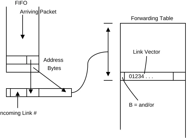
[image:22.612.154.464.348.578.2]As indicated earlier, Autonet packets contain short addresses. In our implementation a short address is 11 bits, although increasing it to 16 bits would be a straightforward design change. The short address is contained in the first two bytes of a packet.
Figure 6: Interpretation of Switch Forwarding Table
alternative ports that could forward the packet. The switch will choose the first port that is free from this set. If several of the ports are free then the switch chooses the one with the lowest number. When the broadcast flag is 1, the port vector indicates the set of ports that must forward the packet simultaneously. Forwarding will not begin until all these ports are available. A broadcast entry with all 0’s for the port vector tells the switch to discard the packet.
Because address interpretation in a switch requires just a lookup in an indexed table, it can be done quickly by simple hardware. Specification of alternative ports allows a simple form of dynamic multipath routing to a destination. For example, multiple links that interconnect a pair of switches can function as a trunk group. Including the receiving port number in the forwarding table index has several benefits; it provides a way to differentiate the two phases of flooding a broadcast packet (see section 6.6.6); it allows one-hop switch-to-switch packets to be addressed with the outbound port number; it provides a way to prevent packets with corrupted short addresses from taking routes that would generate deadlocks.
The mechanism for interpreting short addresses allows considerable latitude in the way short addresses are used. We have adopted the following assignments:
Short Address Packet Destination
0000 From a host; the control processor of the switch attached to the active host port
0001 - 000f From a switch; the switch or host attached to the addressed switch port
0010 - ffef Particular host or switch (packet discarded if address not in use) fff0 - fffb Packet discarded (reserved address values)
fffc From a host; loopback from switch attached to the active host port
fffd Every switch and every host fffe Every switch
ffff Every host
Here each short address is expressed as 4 hexadecimal digits, but prototype switches interpret only the low order 11 bits of these values.
As part of the distributed reconfiguration algorithm performed by the switches, each useable port of each working switch in a physical installation is assigned one of the short addresses in the range “0010” through “ffef”. The assignment is made by partitioning a short address into a switch number and a port number, and assigning the switch numbers as part of reconfiguration. The forwarding tables are filled in to direct a packet (from any source) containing one of these destination short addresses to the switch control processor or host attached to the identified port. If the address is not in use, then the forwarding tables will at some point cause the packet to be discarded. The forwarding tables also discard packets that arrive at a switch port that is not on any legal route to the addressed destination; such misrouted packets may occur if bits in the destination short address are corrupted during transmission.
processor is told the port on which the packet arrived and knows its own switch number. Thus it can reply with a packet containing the host’s short address.
The forwarding tables in every switch will reflect a packet addressed to “fffc” back down the reverse channel of the link on which it was received. Thus, packets sent by a host to this address will be looped back to that host. This feature is used by a host to test its links to the network.
A packet addressed to “ffff” from a host or switch will be delivered to all host ports in the network. (Section 6.6.6 describes the flooding pattern used.) The addresses “fffd” and “fffe” work in a similar way.
Finally, the addresses “0001” through “000f” are reserved for one-hop packets between switches. Each switch forwarding table directs a packet so addressed to be transmitted on the numbered local port if the packet is from port 0 (the control processor port); it directs transmission to port 0 if the packet is from any other port.
6.4 Scheduling Switch Ports
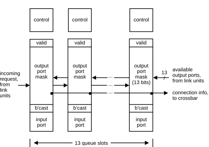
Once the appropriate entry has been read from a switch’s forwarding table, the next step in delivering a packet is scheduling a suitable transmission port. Scheduling needs to be done in a way that avoids long-term starvation of a particular request. The availability of the Xilinx programmable gate array allowed this problem to be solved by the simple strategy of implementing a strict first-come, first-considered scheduler.
Figure 7 illustrates the scheduling engine which contains a queue of forwarding requests. The queue slots are the columns in the figure. Only 13 slots are required because with head-of-line blocking, each port can request scheduling for at most one packet at a time; only the packet at the head of the FIFO is considered. Each queue slot can remember the result of a forwarding table lookup along with the number of the receive port that is requesting service.
When a request arrives at the scheduling engine, the request shifts to the right-most queue slot that is free. Periodically a vector representing the free transmit ports enters the scheduling engine from the right. This vector is matched with occupied queue slots proceeding from right to left, in the arrival order of the requests. Each forwarding request in turn has the opportunity to capture useful free ports.
If a request is for alternative ports (broadcast = 0), then it will capture any free transmit port that matches with the requested port vector. If multiple matches occur, then the free port with the lowest number port is chosen. For alternative ports, a single match allows the satisfied request to be removed from the queue and newer requests to be moved to the right. The satisfied request is output from the scheduling engine and is used to set up the crossbar, allowing packet transmission to begin.
input port output port mask b'cast valid control incoming request, from link units input port output port mask b'cast valid control input port output port mask (13 bits) b'cast valid control
13 queue slots ...
...
...
available output ports, from link units
connection info, to crossbar
•
•
•
[image:25.612.138.476.86.324.2]13 /
Figure 7: Scheduling Engine for Switch Output Ports
The scheduling engine can accept and schedule one request every 480 ns and thus is able to process up to 2 million requests per second.
Notice that the scheduling engine allows requests to be serviced out-of-order when useful free ports are not suitable for older requests. Queue jumping allows some requests to be scheduled faster than they would be with a first-come, first-served discipline. Also notice that a broadcast request will effectively get higher and higher priority until it is at the head of the queue. Once there, the request has first choice on free transmit ports; each time a needed port becomes free, the broadcast request reserves it. Thus, the broadcast request is guaranteed to be scheduled eventually, independent of the requests being presented by the other receive ports.
6.5 Port State Monitoring
Our goal of automatic operation requires that the network itself keep track of the set of links and switches that are plugged together and working, and determine how to route packets using the available equipment. Further, the network should notice when the set of links and switches changes, and adjust the routing accordingly. Changes might mean that equipment has been added or removed by the maintenance staff. Most often changes will mean that some link or switch has failed.
The mechanism for monitoring port states has several layers. The lowest layer is hardware in each link unit that reports hardware status to the control processor of the switch. The next layer is a status sampler implemented in software that evaluates the hardware status of all ports. The third layer is a connectivity monitor, also implemented in software, that uses packet exchange to determine the health and identity of neighboring switches. Stabilizing hysteresis is provided by two skeptic algorithms. We now explain these mechanisms in more detail.
6.5.1 Port States
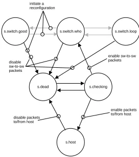
The port state monitoring mechanism dynamically classifies each port on an Autonet switch into one of following six states:
Port State Definition
s.dead The port does not work well enough to use.
s.checking The port is being monitored to determine if it is attached to a host or to a switch.
s.host The port is attached to a host.
s.switch.who The port is being probed to determine the identity of the attached switch.
s.switch.loop The port is attached to another port on the same switch, or is reflecting signals.
s.switch.good The port is attached to a responsive neighbor switch.
Figure 8 illustrates these port states and shows the actions associated with the state transitions. As will be explained in more detail in the next two sections, the state transitions shown as black arrows are the responsibility of the status sampler; those shown as grey arrows are the responsibility of the connectivity monitor. The actions triggered by a transition are indicated by the attached action descriptions.
6.5.2 Hardware Port Status Indicators
Each link unit reports status bits that help Autopilot note changes in the state of the port. These status bits can be read by the control processor of the switch. Some status bits indicate the current condition of a port:
Status Bit Current Port Condition Represented
IsHost last flow control received on link indicates a host is attached XmitOK last flow control received on link allows transmission InPacket transmitter is in the middle of a packet
Other status bits indicate that one or more occurrences of a condition have occurred since the bit was last read by the control processor:
Status Bit Accumulated Port Condition Represented BadCode TAXI receiver reported violation
BadSyntax out-of-place flow control directive, unused command value received, improper packet framing
s.switch.good s.switch.who s.switch.loop
s.dead s.checking
s.host initiate a
reconfiguration
enable sw-to-sw packets
enable packets to/from host disable packets
to/from host disable sw-to-sw packets
Underflow FIFO underflow occurred inside a packet IdhySeen idhy flow control directive received
PanicSeen panic flow control directive received
ProgressSeen FIFO forwarded some bytes or has seen no packets StartSeen start or host flow control directive received
[image:27.612.167.439.275.581.2]There is considerable design latitude in choosing exactly which conditions to report in hardware status bits. As we will see below, all switch-to-switch links are verified periodically by packet exchange. The hardware status bits provide a more prompt hint that something might have changed. If most changes of interest reflect themselves in the hardware status bits, however, then port status changes will be noticed more quickly; Autopilot can use the hardware status change to trigger an immediate verification by packet exchange.
Figure 8: Switch Port States and Transitions
6.5.3 Status Sampler
local control processor (such as the connectivity test or reply packets described in the next section), even though CRC errors are actually detected by software. Based on the status counts accumulated over certain periods, each port is dynamically classified into one of the four states s.dead, s.checking, s.host, and s.switch.who.
When a switch boots, all ports are initially classified as s.dead. This state represents ports that are to be evaluated, but not used. While classified as s.dead, a switch port is forced to send idhy in place of normal flow control to guarantee that the remote port will be classified by the neighboring switch as no better than s.checking. Receiving idhy is not counted as an error when a port is classified as s.dead. When a port has exhibited no bad status for the appropriate period, it moves from s.dead to s.checking. The length of the error-free period required is determined by the status skeptic described in section 6.5.5. A port is directed to send normal flow control when it enters s.checking. A port that has no bad status counts except for receiving idhy stays classified as s.checking.
Once a port is in s.checking, the status sampler waits for idhy flow control to cease, and then tries to determine whether the port is cabled to a switch or to a host. The IsHost bit is used to distinguish the cases. Reflecting ports, and ports cabled to another port on the same switch, will be classified as s.switch.who, because such ports receive the start flow control directives sent from the local switch, causing IsHost to be FALSE. Alternate host ports will send continuous sync commands, but no flow control directives. This pattern generates BadSyntax and makes the IsHost bit useless, so a port showing constant BadSyntax status, but no other errors, is classified as s.host.
When a port’s state is changed to s.host, the local forwarding table is updated to permit communication over the port. The port’s entries in the forwarding table are set to forward all suitably addressed packets to the port and to allow packets received from the port to be forwarded to any destination in the network. Because both active and alternate host ports are classified as s.host, switching to the alternate by a host will cause no forwarding table changes, assuming that the alternate port does not then start producing bad status counts.
When a port is changed from s.checking to s.switch.who, the forwarding table is set to allow the control processor to exchange one-hop packets with the possible neighboring switch. This forwarding table change allows the connectivity monitor to probe the neighboring switch in order to distinguish between the states s.switch.who, s.switch.loop, and s.switch.good.
A port moves back to s.dead from other states if certain limits are exceeded on the bad status counts accumulated over a time period. As indicated in Figure 8, transitions back to s.dead will cause the local forwarding table to be changed to stop packet communication through the port.
6.5.4 Connectivity Monitor
A transition from s.checking to s.switch.who means that the status sampler approves the port for switch-to-switch communication. A port thus approved is always being scrutinized by the top layer of port state monitoring, the connectivity monitor. The state s.switch.who means that Autopilot does not know the identity of the connected switch.
The connectivity monitor tries to determine the UID and remote port number for the connected switch. The connectivity monitor periodically transmits a connectivity test packet on the port and watches for a proper reply. As long as no proper reply is received, the port remains classified as s.switch.who. Thus, a non-responsive remote switch will cause the port to remain in this state indefinitely. To be accepted, a reply must match the sequence information in the test packet and echo the UID and port number of the test packet originator. The connectivity monitor looks at the source UID of an accepted reply packet to distinguish a looped or reflecting link from a link to a different switch. In the former case, the connectivity monitor relegates the port to s.switch.loop; such ports are of no use in the active configuration. In the latter case, the connectivity monitor sets the state to s.switch.good and initiates a reconfiguration of the entire network. The reconfiguration causes all switches to compute new forwarding tables that take into account the existence of the new switch-to-switch link (and possibly a new switch).
The connectivity monitor continuously probes all ports in the three s.switch states. At any time it may cause the transitions to and from s.switch.who shown by grey arrows in Figure 8. In the case of a transition from s.switch.good to s.switch.who, a network-wide reconfiguration is initiated to remove the link from the active configuration. Note from Figure 8 also that a network-wide reconfiguration is initiated when the status sampler, described in the previous section, removes its approval of a port in s.switch.good by reclassifying it as s.dead.
6.5.5 The Skeptics
Two algorithms in Autopilot prevent links that exhibit intermittent errors from causing reconfigurations too frequently. They are the status skeptic and the connectivity skeptic.
The status skeptic controls the length of the error-free holding period required before a port can change from s.dead to s.checking. The length of the holding period for a particular port depends on the recent history of transitions to s.dead: transitions to s.dead lengthen the holding period; intervals in s.host or any of the s.switch states shorten the next holding period.
The connectivity skeptic operates in a similar manner to increase the period over which good connectivity responses must be received before a port is changed from s.switch.who to s.switch.good. This skeptic therefore limits the rate at which an unstable neighboring switch can trigger reconfigurations. The sequences of delays introduced by the skeptic algorithms are still being adjusted.
6.6 Reconfiguration and Routing
no deadlocks can occur, to use all correctly operating links, and to obtain good throughput for the entire network. The distributed reconfiguration algorithm achieves these goals by developing a set of loop-free routes based on link directions that are determined from a spanning tree of the network.
Reconfiguration involves all operational network switches in a five step process: 1. Each switch reloads its forwarding table to forward only one-hop,
switch-to-switch packets and exchanges tree-position packets with its neighbors to determine its position in a spanning tree of the topology.
2. A description of the available physical topology and the spanning tree accumulates while propagating up the tree to the root switch.
3. The root assigns short addresses to all hosts and switches.
4. The complete topology, spanning tree, and assignments of short addresses are sent down the spanning tree to all switches.
5. Each switch computes and loads its own forwarding table, based on the information received in step 4, and starts accepting host-to-host traffic.
Because host packets will be discarded during the reconfiguration process, it is important that the entire process occur quickly, certainly in less that a second. Note that the reconfiguration process will configure physically separated partitions as disconnected operational networks.
As described in the previous section, reconfiguration starts at one or more switches that have noticed relevant port state changes. In step 1 these initiating switches clear their forwarding tables and send the first tree-position packets to their neighbors. Other switches join the reconfiguration process when they receive tree-position packets and they, in turn, send such packets to their neighbors. In this way the reconfiguration algorithm starts running on all connected switches.
The reloading of the forwarding tables in step 1 has two purposes. First, it eliminates possible interference from host traffic, allowing the reconfiguration to occur more quickly. Second, it guarantees that no old forwarding tables will still exist when the new tables are put into service at step 6: co-existence could lead to deadlock and packets being routed in loops.
6.6.1 Spanning Tree Formation
The distributed algorithm used to build the spanning tree is based on one described by Perlman [16]. Each node maintains its current tree position as four local variables: the root UID, the tree level at this switch (0 is the root), the parent UID, and the port number to the parent. Initially, each switch assumes it is the root. A switch reports this initial tree position and each new position to each neighboring switch by sending tree-position packets, retransmitting them periodically until an acknowledgement is received.
If each switch sends tree-position packets to all neighbors each time it adopts a new position, then eventually all switches will learn their final position in the same spanning tree. Unfortunately, no switch will ever be certain that the tree formation process has completed, so the switches will not be able to decide when to move on to step 2 of the reconfiguration algorithm. To eliminate this problem we extend Perlman’s algorithm. We say that a switch S is stable if all neighbors have acknowledged S’s current position and all neighbors that claim S as their parent say they are stable. While transitions from unstable to stable and back can occur many times at most switches, a transition from unstable to stable will occur exactly once at the switch which is the root of the spanning tree. Thus, when some switch becomes stable while believing itself to be the root of the spanning tree, then the spanning tree algorithm has terminated and all switches are stable.
Conceptually, implementing stability just requires augmenting the acknowledgement to a tree-position packet with a “this is now my parent link” bit. A neighbor acknowledges with this bit set TRUE when it determines that its tree position would improve by becoming a child of the sender of the tree-position packet. Thus a switch will know which neighbors have decided to become children, and can wait for each of them to send a subsequent “I am stable” message. When all children are stable then a switch in turn sends an “I am stable” message to its parent.
Step 2 of the reconfiguration process has the topology and spanning tree description accumulate while propagating up the spanning tree to the root switch. This accumulation is implemented by expanding the “I am stable” messages into topology reports that include the topology and spanning tree of the stable subtree. As stability moves up the forming spanning tree towards the root, the topology and spanning tree description grows. When the switch thinking itself to be the root receives reports from all its children, then it is certain that spanning tree construction has terminated, and it will know the complete topology and spanning tree for the network. A non-root switch will know that spanning tree formation has terminated when it receives the complete topology report that is handed down the new tree from the root in step 4. Each switch can then calculate and load its local forwarding table from complete knowledge of the current physical topology of the network. The upward and downward topology reports are all sent reliably with acknowledgments and periodic retransmissions.
6.6.2 Epochs
To prevent multiple, unsynchronized changes of port state from confusing the reconfiguration process, Autopilot tags all reconfiguration messages with an epoch number. Each switch contains the local epoch number as a 64-bit integer variable, which is initialized to zero when the switch is powered on. When a switch initiates a reconfiguration, it increments its local epoch number and includes the new value in all packets associated with the reconfiguration. Other switches will join the reconfiguration process for any epoch that is greater than the current local epoch, and reset the local epoch number variable to match.
algorithm always operates on a fixed set of switch-to-switch links during a particular epoch.
If a switch sees a higher epoch number in a reconfiguration packet while still involved in an earlier reconfiguration, it forgets the tree position and other state of the earlier epoch and joins the new one. If changes in port state stop occurring for long enough, then the highest numbered epoch eventually will be adopted by all switches, and the reconfiguration process for that epoch will complete. Completion is guaranteed eventually because the status and connectivity skeptics reject ports for increasingly long periods.
6.6.3 Assigning Short Addresses
Short addresses are derived from switch numbers that are assigned during the reconfiguration process. Each switch remembers the number it had during the previous epoch, and proposes it to the root in the topology report that moves up the tree. A switch that has just been powered-on proposes number 1. The root will assign the proposed number to each switch unless there is a conflicting request. In resolving conflicts the root satisfies the switch with the smallest UID and then assigns unrequested low numbers to the losers.
A short address is formed by concatenating a switch number and a port number. (The port number occupies the least significant bits.) For a host, then, the short address is determined by the switch port where it attaches to the network. A host’s alternate link thus has a distinct short address. For a switch’s control processor, the port number 0 is used. Because switches propose to reuse their switch numbers from the previous epochs, short addresses tend to remain the same from one epoch to the next.
6.6.4 Computing Packet Routes
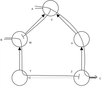
To complete step 5 of the reconfiguration process, each switch must fill in its local forwarding table based on the topology and spanning tree information that is received from the root. Autonet computes the packet routes based on a direction imposed by the spanning tree on each link. In particular, the “up” end of each link is defined as:
1. the end whose switch is closer to the root in the spanning tree;
2. the end whose switch has the lower UID, if both ends are at switches with the same tree level.
The “up” end of a host-to-switch link is the switch end. Links looped back to the same switch are omitted from a configuration. The result of this assignment is that the directed links do not form loops.
To eliminate deadlocks while still allowing all links to be used, we introduce the up*/down* rule: a legal route must traverse zero or more links in the “up” direction followed by zero or more links in the down direction. Put in the negative, a packet may never traverse a link in the “up” direction after having traversed one in the “down” direction.