THE DEVELOPMENT OF A 20 KHZ HIGH-POWER
INVERTER SPOT WELDING POWER SUPPLY
1QIU QI, 2LI XIGONG, 3ZHOU ZHAOFENG, 4SHAO WEI
1,3,4Department of Engineering, Zhejiang University City College, Hangzhou, Zhejiang 310015, China
2 Welding Research and Development Center of Beijing University of Technology, Beijing 100022, China
E-mail: [email protected], [email protected], [email protected], [email protected]
ABSTRACT
A high-power inverter spot welding power supply with 20kHz switching frequency is developed; secondary rectification uses a full wave rectifying circuit of single-coil and double inductors, double tubes, which can effectively improve the switching frequency with the existing device. The integrated high frequency transformer is designed which can effectively decrease various factors that affect the output power, then increase the output current. The power of inverter spot welding power supply approaches 90kVA.
Keywords: 20 khz, Inverter Spot Welding, Rectifying Circuit, The Integrated High Frequency Transformer
1.
INTRODUCTIONSpot welding is widely used in the area of automobile and aircraft manufacturing industry. The core part of the spot welding is power supply, inverter spot welding power source is the product that developed in the mid 1980s, which possess the characteristic of energy saving, small volume, lightweight, fast response etc, which is considered as the most potential resistance welding power source.
Modern inverter power develops towards the direction of high frequency, low voltage, and large current. The inverter frequency for current inverter resistance welding power source mainly lies between 1k~6.5kHz [1], literature [2] even bring the inverter frequency to 10 kHz. Inverter frequency’s improvement will greatly decrease the volume for transformer, and the integrated transformer is made, which can make the integration of soldering turret and transformer become possible, and increases the advantages like control precision etc, which can further highlight the advantages like energy saving, small volume, lightweight, fast response etc. However, due to the factors like the spot welding machine’s high output power (dozens to hundreds, thousands volt-ampere), large current (thousands of volt-ampere), low voltage (only a few volts), it’s difficult to transform the alternating current to direct current, and rectify especially in the circumstance of high frequency, high power. That’s one of the reasons why domestic researchers do not apply the high frequency inverter
technology in the spot welding machine [2]. Literature [5] also shows the inverter frequency cannot be raised randomly when we adopt the center tapped rectifier mode of current double coil, and double tubes, otherwise, the power source might not work properly.
The inverter spot welding power source designed in this paper adopt the autonomous integrated high frequency transformer, the transformer raises the inverter frequency to 20 kHz by using the single coil, double inductor, double tubes, full wave rectifying circuit. The output direct current can reach more than 12000A.
2.
DESIGN FOR POWER CIRCUITThe power circuit is shown in figure 1; circuit breaker, Q1 is the control switch for main circuit. Capacitance, C5~C7 absorbs the peak power for high voltage of power grid, which ensures the safety of the rectification model BR1. Trip 380V, alternating current goes through the BR1 rectification, capacitance C1~C4 filtering, get about 540V direct current. C1, C2 plays the role of low frequency filter, C3, C4 plays the role of filtering. Electric resistance R1, R2 is the equalizing resistance for C1~C4, which play a role of bleeder resistor. Power switch tube is IGBT, which transforms the 540VDC into 20kHz alternating current square wave through the alternate breakover of V1, V4 and V2, V3. C5, C6
68
Figure 1 Power Circuit for Inverter Spot Welding Power Source
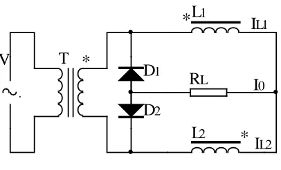
Currently, the secondary rectification for inverter welding machine transformer adopt the center tapped rectifier of double coil, and double tubes, and high power rectifier diode. The secondary rectification for inverter spot welding power source in this paper adopts rectifying circuit of single-coil, double inductor, double tubes, and full wave. Schematic diagram is shown in figure 2. The current doubler rectifier of secondary transformer only possess one set of coil, no center tap, and alternating current for each half cycle is conducted through only one diode. The back pressure that diode bear is the same as the secondary voltage of transformer, which is a kind of rectifying circuit that suitable for low, medium voltage and in the condition of large output current. The author use this kind of circuit to make the inverter spot welding power source of 20kHz switching frequency, 4V voltage, 300A current in the early days. In order to further confirm whether this kind of rectifying circuit is suitable for high frequency, high power inverter spot welding power source, the author made the inverter of 20kHz switching frequency, power 40kVA, and the inverter’s floating voltage of maxima duty cycle 5.14V[7] lately. The research work of this paper is to maintain the switching frequency 20kHz, upgrade the power to 90kVA through the use of the new integrated high frequency transformer coordinate the rectifying circuit and further promote the power density.
T
R
L
L
D
D
V
*
*
*
I
I
I
0 12 L
L1
L2 1
2
Figure 2 Rectifying Circuit Schematic Diagram of Single-coil, Double Inductor Double Tubes, and Full
Wave
3. THE DESIGN FOR INTEGRATED HIGH
FREQUENCY TRANSFORMER
3.1 The factors that affect output current
1) Sin effect [3] is the phenomenon that effective sectional area for guide line reduced and actual electric resistance increases when the wire goes through the alternating current. The higher the alternate frequency is, the more obvious this phenomenon is. Penetration depth, Δ is often used to characterize the function degree for skin effect; it indicates the radial depths that the alternating current can reach along the guide line. Δ varies with the alternate frequency for electric current, f, magnetic conductivity of guide line, μ, and the electric conductivity, γ, the relationship is presented as following:
µγ
π
ωµγ
f
1
2
=
=
∆
(1) [image:2.612.321.524.298.421.2]should be less than two times penetration depth. When the sectional area that guide line request is larger than the maxima effective diameter that decided by the penetration depth, the parallel winding of stranded conductor of minor diameter is adopted, which can effectively decrease the negative impact that caused by skin effect.
2) Proximity effect is more severe than skin effect; when the electric current passes the adjacent guide line, which will produce the adjustable magnetic field and cause the eddy current, eddy current interact with the electric current, which cause the electric current converge on the contact surface of the two conductor, and the magnitude of eddy current increase along with the increase of the coil layers according to the index law. The higher frequency is, the effect is more obvious. Due to the existence of the proximity effect, the first and second times winding of transformer should reduce the layers of winding, and use the staggered winding. The coiling of minor diameter or the slice of thin thickness can also reduce the loss.
3) The leakage reactance of the transformer mainly consists of two parts, which is the leakage inductance of the first and second side windings. The leakage inductance of transformer essentially is a linear reactance, which is the same as the payload, and restricts the electric power output power. Leakage inductance of high frequency transformer is the important factor that affects the regular work for inverter circuit, transformer of small leakage inductance should be designed, core material, shape and dimension should be appropriately selected, and realize by reduce the distance between the first and second winding, the ratio of copper and iron, width to thickness ratio, the ratio of turn to turn distance and coil diameter and other methods [3].
4) Another factor that restricts the output power is the alternating current transmission line of transformer secondary. For the link of the transformer secondary and diode transmit the alternating current when it works, and this link must keep certain length according to the packaging characteristic of the inverter power source. The distributed inductance of this link will restrict the large output current, the higher the switching frequency of inverter is, and the alternating current impedance of the distributed inductance is larger, and the impact on the electric current is more serious [5].
3.2 Transformer Design
High frequency spot welding transformer differ from the arc welding transformer, its characters
mainly consists of low secondary voltage, large electric current, low duty cycle, discontinuous work. The frequency of the transformer is 20 kHz, the rectifying circuit in diagram 2 is used, and no center tap exists in transformer secondary side in this paper. This paper designed the transformer of 90kVA capacity, 20% duty cycle.
3.2.1 The Selection of the Core Material
Currently, the common or the high frequency materials of promising application prospect are ferrite and amorphous materials (crystallite). The past and current high frequency transformer of inverter mostly uses ferrite core. Amorphous materials possess high saturation magnetic induction, Bs, which is three times of ferrite while compared with ferrite; the same capacity of core output power is two times greater than ferrite, strong overloading resistance, less loss, which is 1/2~1/5 of ferrite, and high permeability, which is ten times greater than ferrite, exciting power is low,
curie temperature is 470 ℃, which is three ti ferrite, and possess the advantages like good
thermal stability. Especially when it is used for 20~50 kHz, it can replace the ferrite, and silicon steel [3]. The amorphous material is used to make core in this paper.
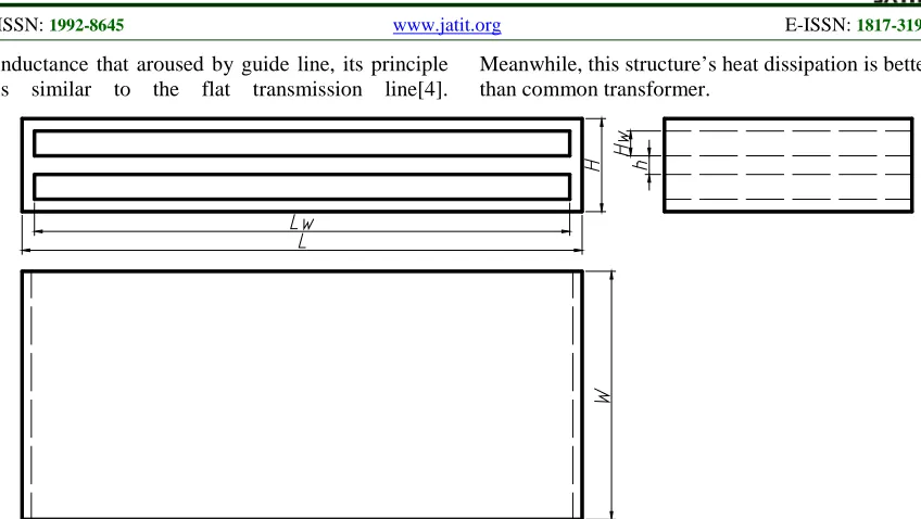
3.2.2 Core Structure
inductance that aroused by guide line, its principle is similar to the flat transmission line[4].
[image:4.612.96.520.70.309.2]Meanwhile, this structure’s heat dissipation is better than common transformer.
Figure 3 Orthographic Views for Transformer Magnetic Core
3.2.3 Valid core Sectional Area
4 1
1
10
−
×
=
KSBN
f
U
(2)U1 is the voltage of primary coil in the formula
(unit: V); K is the waveform factor. Square wave take 4; S is the effective sectional area (unit: cm2); B is the working magnetic flux density (unit: T); N1 is the number of turns for primary coil, N1=34;f is
the working frequency (unit: Hz).
The known saturation magnetic induction BS=1.25T, it can get B=0.8T, primary voltage
Ul=513V, the maxima duty cycle is 0.8, the number
of turns for secondary coil, N2=1, working
frequency, f=20kHz. The calculation S=2.947cm2 according to the formula. It’s important to note that the transformation ratio is 34:1, which is the 68:1while compare with the common transformer.
3.2.4 The Transformer winding
Secondary current for transformer is designed according to the 12000A specification; the electric current 2683 is converted according to 20% duty cycle, primary current is converted as 79, the current density for guide line, Jl=6A/mm2,guide line section is 13.2mm2. Due to the cooling condition of the secondary guide line is good, the electric density of guide line, J2=9A/mm2, the section of guide line is 298mm2. The primary side of the uses strands of varnished wire to be parallel winded to decrease the skin effect. In order to decrease the leakage inductance of transformer, and the distributed inductance and proximity effect caused by guide line of the coil, layers of 1 mm thin copper coil is made into secondary side.
3.3 Design of the Integrated High Frequency Transformer
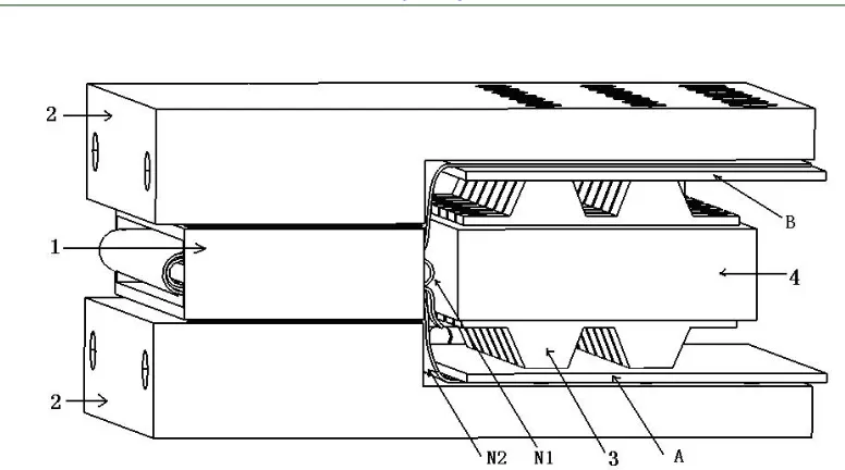
The transformer plus rectifier is used to be called the integrated transformer. The rectifier selected 14 common cathode schottky rectifier models of 600A, 45V. The radiator is cooled by water, and combines the designed transformer to form the integrated high frequency transformer [4]. The specific structure is shown in figure 4, as shown in the diagram: 1, transformer core; N2, secondary coil of transformer;
N1, primary coil of transformer; A, B, output
terminal of motherboard for the transformer secondary coil. 2 Cool down the water cooled heat sink of the transformer; 3, rectifier tube;4,Cool down the water cooled heat sink of the rectifier tube. The transformer core is firmly stuck between the two transformer’s water cooled heat sink, the cooling condition is good. Both ends of secondary coil, N2 are separately press on the water cooled
Figure 4 The integrated high frequency transformer
4. TEST ANALYSES
The above-mentioned technical measures are adopted; the small size inverter spot welding power source with 20 kHz switching frequency is made. High frequency transformer weights 1.2kg, the volume for integrated transformer is 220×181×109(mm), the overall size for the power
is 330×300×350(mm), the input voltage is three phase 380V; the full bridge inverter is used; the transformation ratio for transformer is 34:1; 14 pairs of rectifier tubes; the power approaches 90kVA. The voltage waveform of transformer input while welding after the match of electric holder is shown in figure 5, the effective value for output voltage is 13.19V.
Figure 5 The output voltage waveform of transformer
Owing to the limited condition, the power output power is converted by the measurement of electric current of the transformer original end. The measurement model of the transformer original end is CHG-1000, the measured resistance value that jointed by the input end is 24Ω, and the voltage of the measured resistance 1V represents the electric current for transformer original end 41.7A, the
[image:5.612.186.437.432.609.2]Figure 6 The electric current for the transformer original end (low carbon steel)
5. CONCLUSIONS
(1) The copper loss of the rectifying circuit is low that designed in this paper, and the fabrication process is simple, which is more suitable for work as the secondary side rectifying circuit of the high frequency inverter spot welding power source while compared with the center tapped rectifying circuit of double coils.
(2) The flat integrated high frequency transformer that designed in this paper, which can decrease the skin effect, proximity effect, leakage reactance and the output impedance effectively. Therefore, the output current can be increased, and further decrease the volume for inverter power as well, the power density is promoted.
(3) Under the condition of 20 kHz switching frequency, the power of inverter spot welding power supply can be further improved.
REFRENCES:
[1] http: //www.damientech.com /us/spot_welders. Htm.
[2] HAN Yuqi, CHEN Zhiwei, DAI Jianming, etc. “The principle and application of DSP inverter DC spot welder”. Electric Welding Machine, Vol. 41, No. 5, 2011, pp.54-56.
[3] LI Chunxu, ZHANG Xuehong, LI Fang. “Effects of Leakage inductance of high frequency transformer on work-state of IGBT welding inverter power source”. Electric Welding Machine, Vol. 34, No. 1, 2004, pp.42-45.
[4] LI Xigong, LU Zhenyang, HUANG Pengfei,
QIU Qi, A rectifier transformer and its application method. Chinese Patent: ZL 200810117537.0, 2008.
[5] LI Xigong, YANG Ludong, ZHANG Liang. “20 kHz high frequency inverter power supply for resistance welding”. Transactions of the China Welding Institution, Vol. 27, No. 2, 2006, pp.105-107.
[6] WANG Zhiqiang, “Switching power supply design”. Beijing: Publishing House of Electrics Industry, 2006.