APPLICATION OF NEURAL NETWORK TRAINED WITH
META
-
HEURISTIC ALGORITHMS ON FAULT DIAGNOSIS
OF MULTI
-
LEVEL INVERTER
1
M.SIVAKUMAR, 2R.M.S.PARVATHI
1Research Scholar, Department of EEE, Anna University, Chennai, Tamilnadu, India.
2Principal, Sengunthar College of Engineering, Tiruchengode, Tamilnadu, India.
Email: [email protected], [email protected]
ABSTRACT
Growing industrial need makes the choice of fast response, accurate and efficient systems. The Multilevel inverter based induction drives (MLID) are the best solution for the industrial drive needs, which reduces the harmonics and increases the efficiency of the system. And also the need for hybrid electric vehicles increases the need of an efficient traction system with the use of multilevel inverters. As multilevel inverter has many semi-conductor switches, it is difficult to identify the fault in it. In this paper a new fault diagnosis method by using the total harmonic distortion (THD) of the voltage waveform and to classify the fault, neural network (NN) trained with back propagation, genetic algorithm (GA) and also with particle swarm optimization (PSO) is applied and the results are compared. Results shows that NN trained with PSO gives fast response in training algorithm when compared to BP and GA. Here a cascaded multi-level inverter based three-phase induction motor drive is taken as the test system. Mat-lab software is used to analyse the effectiveness of the test system and results are tabulated.
Keywords: Fault diagnosis, neural network, Particle Swarm Optimization, Genetic Algorithm, Cascaded
multi-level inverter, Total Harmonic Distortion.1. INTRODUCTION
The multi-level inverters (MLI) are essential in the efficient operation of the hybrid electric vehicles, Flexible AC Transmission System (FACTS), Motor Drives etc.. The problem with the MLI is the number of switches present in it. Increase in number of level increases the number of switching devices. And for three-phase multilevel inverter still has more switches and if in any switch fault happens, that stops the entire process and also makes the change in the output voltage wave shape. Use of more number of power semiconductors are the main drawback of MLI’s and due to this reason MLI may be considered as reliable. But as MLI are used in high power applications, the reliability of the power electronics equipment is more significant.
The conventional protection systems used in drives are passive devices such as fuses, overload
relays, and circuit breakers to protect the inverter systems and the induction motors.
There are a number of intelligent systems approaches which have been investigated in signal fault diagnosis. Rule-based expert systems and decision trees are two traditional diagnostic techniques, but they have serious limitations.
A rule-based system often has difficulties in dealing with novel faults and acquiring complete knowledge to build a reliable rule-base. A decision tree can be very large for a complex system and it is also system dependent such that even small engineering changes can mean significant updates [12].
More recently model based approaches, fuzzy logic, Artificial Neural Networks (ANN), Case Based Reasoning (CBR) are popular techniques used in various fault diagnostics problems in electrical systems. In particular ANN”s has been shown to be effective in many automotive fault diagnostic applications [13] [14] [15] [16]. The feature extraction using neural network takes more number of neurons. This makes the classification time consuming and increase in utilized memory. The principal component analysis is utilized in the feature extraction process to reduce the NN input size. A lower dimensional input space will also usually reduce the time necessary to train an NN, and the reduced noise can improve the mapping performance. The genetic algorithm is applied to select the valuable principal component [8]. Quick identification of fault conditions and a modulation pattern is generated according to the each single fault and it is classified without any extra sensors [3]. Classification of the fault for each MLI topology and the remedial action are described [9]. MLI can operate in faulty conditions [9]. Neutral point Coupling inverter plays main role in industrial drives, so the fault tolerant operation of this inverter is also mandatory.
ANPC inverter is introduced, which operates in faulty conditions [5]. Even though lot of literatures gives the remedial action and different fault classification methods it is important to classify the
fault accurate and fast to trigger the remedial action. Intelligent systems incorporated with meta-heuristic algorithm are highly applicable in electrical control system, as it deserves it. Application from genetic algorithm to neural network training has many advantages like fast operation of neural network and provides accurate results. But in this approach Direction of arrival (DOA) is the problem, which can be solved by Multi-layer perception neural network (MLP-NN).
The layer size can be reduced by using GA [10]. NN trained GA is also used for weather forecasting but it is not easy to predict [4]. Particle Swarm Optimization (PSO), which is built by swarm intelligent has also used for training the neural network. The short term-load forecasting is done using the NN trained PSO. The potential solutions flow through the problem hyperspace with accelerated movement towards the best solutions and it makes the forecasting high precision [1].
2 CASCADED MULTI-LEVEL INVERTER
DRIVE
For testing purposes a seven-level cascaded multi-level inverter driving induction motor shown in figure 1 is used. The closed switch faults and open switch faults are applied to the single phase of the three-phase inverter for simplicity. The fault occurs in the MLID affects the voltage level and the shape of the output voltage wave form. This waveform analysed with total harmonic distortion (THD). Each switch fault creates different waveforms due to the different levels. Each faults has different THD values. Figure 4 &5 portrayed below shows the waveforms due to the fault in each switch of a single cell and its THD values. Using the THD data, identification of switch fault can be done by training the neural network (NN).
3.FAULT DIAGNOSIS SYSTEM
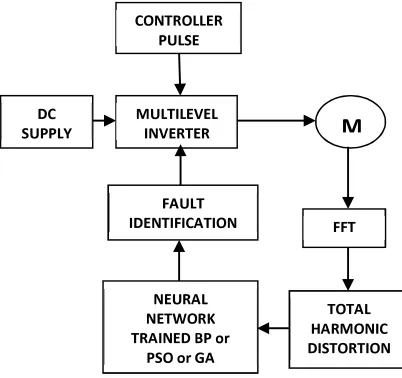
The fault diagnosis system is used to diagnose the fault location and type of the fault using the THD value. The fig. 2 shows the block diagram of the proposed Fault diagnosis system. During the operation of MLID the FFT is applied to the line voltage of the motor terminals and also THD value voltage is monitored.
If the THD value is within the limit (i.e. no fault condition) then the neural network output ensures the normal operation of the system. When there is a fault THD changes, according to that the output of the NN changes which classifies the fault and TRIAC is turned on accordingly.
[image:3.612.101.302.250.439.2]
Fig. 2. Fault Diagnosis System
The values, if it is in limit (i.e. no fault occurrence) then the neural network gives the output as normal condition, when the output of the THD changes, according to that neural network which is trained according to that classifies the fault and the TRAIC is turned on according to that fault.
Fig 3. Adding A Redundant Leg
Here neural network is trained with different meta-heuristic algorithms. GA and PSO are used to select the optimal weight values. So the accurate and faster classification is achieved.
A redundant leg method is proposed which compensates the fault voltage faster for PMSM [11]. That circuit is remodelled for cascaded MLI as shown in the fig. 3. This performs better in motor controlling operation. Here different meta- heuristic algorithms like GA and PSO are used to train the NN to select the optimal weight values which gives the accurate and faster classification of faults.
4. NEURALNETWORKTRAINEDUSING
META-HEURISTICSEARCH
ALGORITHMS
Generally neural network is trained by Back propagation algorithm [7]. Here the PSO algorithm and GA is applied for training the neural network [1] [4]. The Procedure is present below for BP, GA and PSO algorithms for selecting the weights, which used in the training of neural network. The objective function for GA and PSO is to minimize the mean square error.
4.1. NV Trained Bp: CONTROLLER
PULSE
MULTILEVEL INVERTER
FAULT IDENTIFICATION
NEURAL NETWORK TRAINED BP or
PSO or GA
FFT
TOTAL HARMONIC DISTORTION DC
4.1.1. Pseudo code:
1. Generate a feed forward neural network with a given no. of layers, no. of neurons in hidden layers, transfer functions. 2. Initialize weights with small, random
values.
3. While stopping condition is not true for each training pair (input/output):
• Each input unit broadcasts its value to all hidden units.
• Each hidden unit sums its input signals & applies activation function to compute its output signal.
• Each hidden unit sends its signal to the output units
• Each output unit sums its input signals & applies its activation function to compute its output signal
4.2. Back Propagation Stage:
1. Each output computes its error term, its own weight correction term and its bias (threshold) correction term & sends it to layer below.
2. Each hidden unit sums its delta inputs from above & multiplies by the derivative of its activation function; it also computes its own weight correction term and its bias correction term.
3. Each output unit updates its weights and bias
4. Each hidden unit updates its weights and bias:
–Each training cycle is called an epoch. The weights are updated in each cycle –It is not analytically possible to determine where the global minimum is.
5. Eventually the algorithm stops in a low point, which may just be a local minimum. 6. The final updated weights and biases are assigned to the neural network with which network gives minimum error.
7. Simulate the neural network with a test input pattern to check the network’s performance.
4.3. NN Trained Ga: 4.3.1. Pseudo code:
1. With a given number of layers (2), given no. of neurons & transfer functions (tansig, purelin) initialize the neural network to obtain initial weight matrices. 2. Unwrap the weight & bias matrices in a
single row vector to form first chromosome.
3. Randomly generate the rest of the chromosomes (i.e. Population size-1). 4. For every chromosome: reform into its
original weight and bias matrices and simulate the neural network & obtain the Mean squared error.
5. Save minimum MSE for every generation in a variable.
6. Generate new population using following steps:
a) [Selection] Select two parent chromosomes from a population according to their fitness (the better fitness, the bigger chance to be selected).
b) [Crossover] With a crossover probability cross over the parents to form a new offspring (children).
c) [Mutation] With a mutation probability mutate new offspring at each locus (position in chromosome).
7. [Replace] Use new generated population for a further run of algorithm.
8. [Test] If the minimum MSE threshold is reached, stop, and return the best solution to the main program.
9. Form the weight & bias matrices with the obtained best solution and row, column indices.
10. Assign the obtained weight and bias matrices to the neural network.
4.3.1.1.selection: roulette wheel selection
The roulette wheel selection method is used to select the two parents. Roulette wheel selection mechanism is explained as following.
S = Y / Sum(Y) Y is fitness of each chromosome.
S1= Rand () S2=0 J=1
While S2 > S1 S2=S2+S (J) J++ End
Parent = Population (J, :)
4.3.1.2 cross over: arithmetic cross over
Arithmetic cross over is used to generate a new offspring from two selected parents. Two offspring are generated using the following equation
Offspring1=a*parent1+ (1-a)*parent2; Offspring2= (1-a)*parent1+ a*parent2;
Where ‘a’ is random weighting factor. Mutation:
Mutation operator is defined as following,
Ф=1-2*Rand ()
Z=inverse error function (Ф) * 20.5.
Offspring = z*σ (l) + parent. σ =
(maxweight - minweight)/10.
σ is reduced in each iteration. σ = σ / 1.05.
4.4. Nn Trained Pso: 4.4.1 Pseudo code:
1) With a given number of layers (2), given no. of neurons & transfer functions (tansig, purelin) initialize the neural network to obtain initial weight and bias matrices.
2) Unwrap the weight & bias matrices in a single row vector to form first particle. 3) Randomly generate the rest of the
particles (i.e. Population size-1).
a) For every Particle: Reform into its original weight and bias matrices and simulate the neural network & obtain the Mean squared error. b) Save minimum MS for every
generation in a variable.
c) If the mean squared error for every particle is less than that in the previous iteration then mark its position as the personal best position.
d) Mark the particle as Global best particle if it has minimum MSE than the rest of the particles. 4) [Test] If the minimum MSE threshold
is reached, stop, and return the best solution to the main program.
5) Form the weight & bias matrices with the obtained best solution and row, column indices.
6) Assign the obtained weight and bias matrices to the neural network.
7) Simulate the neural network with a test input pattern to check the network’s performance.
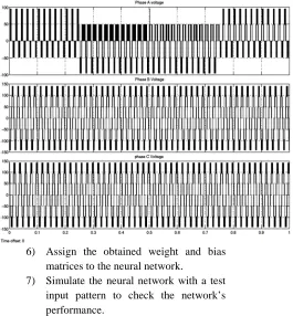
[image:5.612.318.583.376.662.2]Fig. 5. Waveforms of Phase A, B and C Without any fault in the MLID system
5.RESULTSANDDISCUSSION
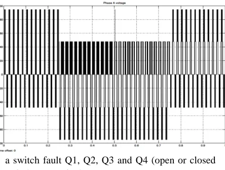
The test setup is shown as a block diagram Fig. 2. The MLID is operated for 1 sec. within that 0.01 sec, 0.25 sec, 0.5 sec and 0.75 sec are induced with
a switch fault Q1, Q2, Q3 and Q4 (open or closed switch) respectively.
Fig. 6. Fault At The Phase A At Cell A1; Q1, Q2, Q3 And Q4 Fault As In The Fig
In Fig. 5 due to fault in switches change in THD values are shown. These values are given as the input to the neural network and output is taken
as zero and 1 as binaries.
Fig. 7. THD values for the Switch fault Q1, Q2, Q3 and Q4
Fig. 7. Shows the pattern of the THD for the fault applied in cell A1 for the simplicity. Due to the periodically applied fault change in waveform of voltage make the pattern in THD calculation. This pattern is feed to the neural network to train. If any of this fault occurs it can easily classify the fault phase and cell and also it can perform the remedial action.
5.1. Parameters Used For Nn Trained Bp:
1)No. of layers= 2.
2)No. of neurons in input layer= 3.
3)Mean squared error (MSE)= 1.3304e-008. 4)Number of epochs trained= 1000.
5.2. Parameters Used For Nn Trained Ga:
1)Minimum error threshold= 0.04. 2)Population size= 100.
3)Maximum no. of epochs=1700. 4)Fitness function= Mean squared error. 5) No. of layers=2.
6) No. of neurons in input layer= 4. 7) Number of epochs trained= 78. 8) Mean squared error (MSE) =
0.008744818256473
5.3. Parameters Used For Nn Trained Pso:
1) Minimum error threshold= 0.000005. 2) Population size=25.
[image:6.612.67.549.50.298.2] [image:6.612.85.307.443.611.2]4) Maximum no. of epochs= 1700. 5) Fitness function= Mean squared error.
6) No. of layers=2.
[image:7.612.51.296.227.481.2]7) No. of neurons in input layer=2. 8) No. of epochs trained= 1631. Mean squared error (MSE)= 1.4059e-009.
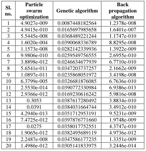
Table I: COMPARISON OF BP,GA AND PSO ON NN TRAINING
From Table 1 it can be seen that PSO algorithm gives lesser value of mean square error and it converges faster due to its large search space. Velocity calculation makes the search accelerated.
Fig. 8 Iteration Number Vs Mean Square Error (MSE) For BP, GA And PSO Algorithms.
The fig. 8 shows the graph of convergence for the BP, GA, and PSO. From the graph shown in Fig.8 it is observed that PSO gives accurate solution, compared to all the other methods.
I. CONCLUSION
The Neural network trained by meta-heuristic algorithms is used to get optimal solutions, which makes the diagnosis system to identify the fault faster and give the control signal. The BP training is compared with GA and PSO to produce optimal solution under fault condition. The test system is tested with the mat-lab software with coding. The objective function used for this test system is the mean square error (MSE) on classification of fault and the results shows that the PSO algorithm gives fast and accurate results compared to the other methods.
REFERENCES
[1] Bashir. Z.A., and El-Harwary. M.E. “Applying Wavelets to Short-Term Load Forecasting Using PSO-Based Neural Networks”, IEEE Transactions on Power System, Vol. 24, 20-27, 2009
[2] Boo Junyou , “Stock Price forecasting using PSO-Trained neural networks”, IEEE Transactions 2009
[3] Brando. G, Dannier. A and others. “Quick identification technique of fault conditions in cascaded H-Bridge multilevel converters”, International Aegean Conference on Electrical Machines and Power Electronics, 491-497, 2009
Sl. no.
Particle swarm optimization
Genetic algorithm
Back propagation
[4] Jasmeen Gill. Er and others , “Training Back propagation Neural Networks with Genetic Algorithm for Weather Forecasting” IEEE 8th International Symposium on Intelligent System and Informatics, 465-469, 2011
[5] Jun Li, Alex Q.Huang and others, “Analysis and Design of Active NPC (ANPC) Inverters for Fault-Tolerant Operation of High-Power Electrical Drives. IEEE Transactions on Power Electronics, Vol. 27, 519-533, 2012.
[6] Sedghi. S and Dastfan. A,“Fault Detection of a Seven Level Modular Multilevel via Voltage Histogram and Neural Network” 8th International Conference on Power Electronics – ECCE Asia, 1005-1012, 2009
[7] Surin Khomfoi and Leon M.Tolbert, “Fault Diagnosis System for a Multilevel Inverter Using a Neural network” IEEE Transaction on power electronics, vol. 22, 1062-1069, 2007
[8] Surin Khomfoi and Leon M.Tolbert , “Fault Diagnosis and Reconfiguration for Multilevel Inverter Drive Using AI-Based Techniques” IEEE Transactions on Industrial Electronics, Vol. 54, 2954 – 2968, 2007
[9] Pablo Lezana, JosepPou and others, “Survey on Fault Operation on Multilevel Inverters. IEEE Transactions on Industrial Electronics, Vol. 57, 2207-2218, 2010
[10] Pour, H.M., and others, “Performance of Neural Network Trained with Genetic Algorithm for Direction of Arrival Estimation” International Conference on Mobile Computing and Wireless Communication , 197-202, 2006
[11] Rammohan Rao Errabelli, and other, “Fault-Tolerant Voltage source Inverter for Permanent Magnet Drives” IEEE Trans. On Power Electronics, Vol.27, 500-508, 2012 [12] Fenton, W.G., T.M. McGinnity and
others, “Fault diagnosis of electronic systems using intelligent techniques: A review” IEEE Trans. On Syst. Man. Cybernet., Vol.31, 269-281, 2000
[13] Feldkamp, L.A. and G.V. Puskorius, “A signal processing framework based on dynamic neural networks with application to problems in adaptation, filtering and classification” IEEE Proc., Vol.86, 2259- 2277, 1998
[14] Guo, H., J.A. Crossman, Y.L. Murphey and others, “Automotive signal diagnostics using wavelets and machine learning” IEEE Trans. On Vehic., Vol.49, 1650-1662, 2000 [15] Crossman, J.A., H. Guo, and others,
“Automotive signal fault diagnostics-part I: Signal fault analysis, signal segmentation, feature extraction and quasi-optimal feature
selection” IEEE Trans. on Vehic. Technol., vol.52, 1063-1075, 2003