© 2018, IRJET | Impact Factor value: 6.171 | ISO 9001:2008 Certified Journal | Page 1367
Electricity Generation Using Speed Breaker
Mrs. S.S Pitre
1, Mr. Rahul Raj
2, Mr. Sachin Raina
3, Mr. Akash Bhoria
4, Mr. Alok Kumar
51Asst. Professor, Dept. of Electrical Engineering, NBN Sinhgad School of Engineering, Pune, India
2,3,4,5 Student, Dept. of Electrical Engineering, NBN Sinhgad School of Engineering, Pune, India
---***---Abstract -
Energy is the primary need for survival especiallyfor mankind. Everything that happens in the surrounding is the expression of flow of energy in one of the forms. But in this fast moving world, population is increasing day by day and the conventional energy sources are lessening. The extensive usage of energy has resulted in an energy crisis over the few years. Therefore, to overcome this problem we need to implement the techniques of optimal utilization of conventional sources for conservation of energy. This project includes how to utilize the energy which is wasted when the vehicles passes over a speed breaker. Lots of energy is generated when vehicle passes over it. We can tap the energy generated and produce power by using the speed breaker as power generating unit. The kinetic energy of the moving vehicles can be converted into mechanical energy of the shaft through rack and pinion mechanism which is an electromechanical principle. Then, this mechanical energy will be converted to electrical energy using generator which will be saved with the use of a battery. The energy we save during the day light can be used in the night time for lighting street lights. Therefore, by using this arrangement sufficient energy can be generated to meet various daily need. This work focuses to generate energy from speed breaker by making gear arrangement. To make the system more efficient a pressure transducer i.e. piezoelectric crystal can be used that will convert vehicle pressure into electrical output. The output of system can also be monitored on real time basis using Wi-Fi based module. This will lessen the dependency on energy produced by conventional process to some extent.
Key Words: Electromechanical process, Rack pinion arrangement, Chain sprocket and shaft, Piezoelectric crystal, RTM, Individual usage
1. INTRODUCTION
1.1 Problem Statement
The demand of electricity is increasing rapidly day by day but the production rate is not according to meet the need. Establishing new power plants to produce more electrical energy is not a solution to this problem as per economical point of view. The government and the electricity generating companies is suffering huge losses in electrical power production due to inefficient methodology and various other constraints especially in thermal power plants. The existing huge gap between demand and production can be filled by producing electricity at individual level in order to meet various household needs. To generate electricity to satisfy daily or basic needs various sources can be used that are normally overlooked in daily life, one of these sources include mechanical pressure of vehicles on speed breaker.
1.2 Objective
The generation of electricity using speed breaker is one of the easiest way as now-a -days everyone is having vehicle. It can be widely accepted at individual level because of its low production cost also it doesn’t need any extra effort. Also the piezoelectric crystal which will convert the mechanical pressure in electric output will enhance the system output.
1.3 Scope
The energy generated using speed breaker mechanism can be used to store in a batteries and can be used apart for various purposes. The work basically aims to produce free electricity with no fuel cost, no pollution and with minimum requirement of space.
2. LITERATURE REVIEW
[1] observes customers pull in and out all day, and at least 100,000 cars visit the drive-thru each year. and a newly installed, mechanized speed bump(video) will both help them slow down and harvest some of that coasting energy. The weight of a car is used to throw a lever, explains Gerard Lynch, the engineer behind the Motion Power system developed for New Energy Technologies, a Maryland-based company. "The instantaneous power is 2,000 watts at five miles-per-hour, but it's instantaneous which means some form of storage will be required.
© 2018, IRJET | Impact Factor value: 6.171 | ISO 9001:2008 Certified Journal | Page 1368 India, unlike the top developed countries has very poor
roads. Talking about a particular road itself includes a number of speed breakers. By just placing a unit like the “Power Generation Unit from Speed Breakers”, so much of energy can be tapped. This energy can be used for the lights on the either sides of the roads and thus much power that is consumed by these lights can be utilized to send power to these villages.
[3] The rotor (rotating shaft) is directly connected to the prime mover and rotates as the prime mover turns. The rotor contains a magnet that, when turned, produces a moving or rotating magnetic field. The rotor is surrounded by a stationary casing called the stator, which contains the wound copper coils or windings. When the moving magnetic field passes by these windings, electricity is produced in them. By controlling the speed at which the rotor is turned, a steady flow of electricity is produced in the windings. These windings are connected to the electricity network via transmission lines. IIT Guwahati has evaluated the machine and recommended it to the Assam ministry of power for large scale funding. IIT design department says it is a „very viable proposition‟ to harness thousands of megawatts of electricity untapped across the country every day. A vehicle weighing 1,000 kg going up a height of 10 cm on such a rumble strip produces approximately 0.98 kilowatt power. So one such speed-breaker on a busy highway, where about 100vehicles pass every minute, about one kilo watt of electricity can be produced every single minute. The figure will be huge at the end of the day. A storage module like an inverter will have to be fitted to each such rumble strip to store this electricity. The cost of electricity generation and storage per megawatt from speed-breakers will be nearly Rs 1 crore as opposed to about Rs 8 crores in thermal or hydro power station institute of technology, kanpur.
3. SYSTEM DEVELOPMENT
3.1 Introduction
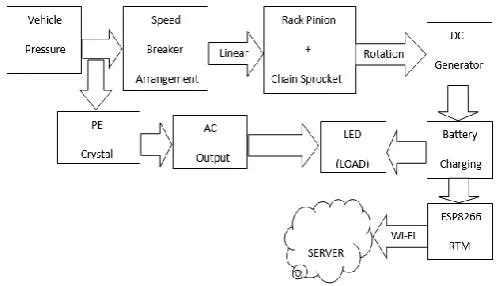
The conversion principle for electricity involves electromechanical process in which rotating output of mechanical arrangement is converted into dc output using dc generator. The piezoelectric crystal uses the pressure of vehicle load transmitted through spring to produce AC electrical output.
The output of vehicle pressure is converted into other forms of energy, including kinetic energy. On road vehicles waste a tremendous amount of energy on speed breakers, where there is a necessity to provide speed breaker to control the speed of the vehicles. The annual rate of growth of motor vehicle population in India has been almost 20 percent during the last decade. There is tremendous vehicular growth in year by year. The increasing traffic and number of speed breakers on roads motivate to manufacture an innovative device which can channelize the energy of vehicles that is wasted on speed breakers to some useful work. In this paper it is mainly focused on the principle of
Potential Energy to Electrical Energy Conventional. Potential energy can be thought of as energy stored within a physical system. This energy can be released or because it has the potential to change the states of objects in the system when the energy is released. If h is the height above an arbitrarily assigned reference point, then Kinetic energy of an object is the extra energy which it possesses due to its motion. It is defined as the work needed to accelerate a body of a given mass from rest to its current velocity. Having gained this energy during its acceleration, the body maintains this kinetic energy unless its speed changes. Negative work of the same magnitude would be required to return the body to a state of rest from that velocity. In this paper it is explained the working of a mechanism to generate power by converting the potential energy generated by a vehicle going up on a speed breaker into kinetic energy.
Generation of electricity mainly involves conversion of mechanical energy into electrical energy and in this process the mechanical energy of vehicles pushing the speed breakers in downward direction using spring is used as a input mechanical source.
The mechanical power transmission is then done using rack-pinion & chain-sprocket arrangement which is then used to rotate the shaft coupled to the dynamo or dc generator producing the electrical output. To enhance the working of entire system piezo electric crystals can be installed which will get the mechanical energy and add up to the overall energy produced The output of the system will obviously depend upon the number of vehicles crossing the speed breaker. The entire system needs a rugged mechanical frame that can be installed beneath the roads. The main advantage of this process is that input to the system is non terminating and is absolutely free of cost, producing considerable amount of output to full fill various daily needs. This will lessen our dependency on conventional method of electricity generation to some extent.
3.2 Proposed Methodology
Generation of energy using speed breaker involves step by step procedure of energy conversion and involves electromechanical process. Mechanical linkage methodologies are used in the process along with piezoelectric crystals to produce desired electrical output.
1. Selecting Suitable Components
2. Assembling and Organizing Components 3. Testing and Monitoring
Initially the pressure of vehicles on speed breaker assembly is used to drive the mechanical arrangement of rack pinion and chain sprocket.
© 2018, IRJET | Impact Factor value: 6.171 | ISO 9001:2008 Certified Journal | Page 1369 The generator uses this input to generate dc electrical output
which is given to LED light.
The mechanical pressure of vehicles is given to piezoelectric crystal which has the property to convert this pressure into AC electrical output.
The output voltage is monitored on Wi-Fi based ESP module which senses the voltage and sends it to local server from where it can be monitored using real time monitoring.
3.3 Working Principle
While moving, the vehicles possess some kinetic energy and it is being wasted. This kinetic energy can be utilized to produce power by using a special arrangement called power hump. It is an Electro-Mechanical unit. It utilizes both mechanical technologies and electrical techniques for the power generation and its storage. Power hump is a dome like device likely to be speed breaker. Whenever the vehicle is allowed to pass over the dome it gets pressed downwards then the springs are attached to the dome are compressed and the rack which is attached to the bottom of the dome moves downward in reciprocating motion.
Since the rack has teeth connected to gears, there exists conversion of reciprocating motion of rack into rotary motion of gears but the two gears rotate in opposite direction. A flywheel is mounted on the shaft whose function is to regulate the fluctuation in the energy and to make the energy uniform. So that the shafts will rotate with certain rpm these shafts are connected through a belt drive to the dynamos, which converts the mechanical energy into electrical energy. The conversion will be proportional to traffic density. Whenever an armature rotates between the magnetic fields of south and north poles, an E.M.F (electro motive force) is induced in it. So, for inducing the E.M.F armature coil has to rotate, for rotating this armature it is connected to a long shaft.
By rotating same EMF, is induced, for this rotation kinetic energy of moving vehicles is utilized. The power is generated in both the directions; to convert this power into one way a special component is used called Zener diode for continuous supply. All this mechanism can be housed under the dome,
like speed breaker, which is called hump. The electrical output can be improved by arranging these power hump in series. This generated power can be amplified and stored by using different electrical devices such as battery. To enhance the working of entire system piezo electric crystals can be installed which will get the mechanical energy and add up to the overall energy produced. The output of the system will obviously depend upon the number of vehicles crossing the speed breaker. The entire system needs a rugged mechanical frame that can be installed beneath the roads. The main advantage of this process is that input to the system is non terminating and is absolutely free of cost producing considerable amount of output to fulfill various daily need. This will lessen our dependency on conventional method of electricity generation to some extent.
For real time monitoring purpose of the produced output voltage ESP8266 is used that will sense the voltage and will send it to server using Wi-Fi created by its own.
3.3.1 Rack-Pinion Mechanism
A rack and pinion is a type of linear actuator that comprises a pair of gears which convert rotational motion into linear motion. The circular pinion engages teeth on a linear "gear" bar – the rack. Rotational motion applied to the pinion will cause the rack to move to the side, up to the limit of its travel. For example, in a rack railway, the rotation of a pinion mounted on a locomotive or a railcar engages a rack between the rails and pulls a train along a steep slope The rack and pinion arrangement is commonly found in the steering mechanism of cars or other wheeled, steered vehicles. This arrangement provides a lesser mechanical advantage than other mechanisms such as recirculating ball, but much less backlash and greater feedback, or steering "feel". The use of a variable rack (still using a normal pinion) was invented by Arthur E Bishop, so as to improve vehicle response and steering "feel" especially at high speeds, and that has been fitted to many new vehicle after he created a special version of a net-shape warm press forging process to manufacture the racks to their final form, thus eliminating any subsequent need to machine the gear teeth. This converts the pressure applied by vehicle into rotary motion.
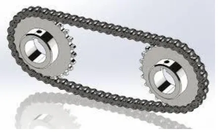
[image:3.595.41.292.213.356.2]© 2018, IRJET | Impact Factor value: 6.171 | ISO 9001:2008 Certified Journal | Page 1370 3.3.2 Chain Sprocket
The chain sprocket used mainly converts the input linear motion into rotational motion to the shaft. The rotation of shaft will act as an input for dc generator which will produce the desired electrical output. Chain and sprocket is useful for when the distance between shafts is relatively large compared to the desired size of the gearing. The sacrifice is typically strength as solid gear teeth are usually stronger than chains. The reason a bike uses a chain and sprocket is that the desired distance between shafts would be inconvenient for gear to gear meshing. Now one could consider a driveshaft like a car but it would be heavier, more awkward to package, and not gain anything relevant in terms of durability. And remember lighter is better for bicycles. So in short, chain and sprocket is the lightest transmission possible that would deliver durability that consumers demand. And that's to say nothing of Derailleur mass vs gearbox for multiple speeds. Bicycles that use shaft drives, a type of rack-and-pinion gear mechanism, have too many disadvantages for mainstream adoption, but they have persisted in niche markets for over a hundred years, mostly through novelty appeal. For instance, the Sonoma D-drive pictured below is sold at Walmart as a commuter bike. Shaft drives never caught on like chain-and-sprocket designs for several reasons. The main problems are weight, higher cost, added complexity, more difficult maintenance, and lower mechanical efficiency. The deal-breaker is that every problem solved by a shaft drive can be solved with a chain case, except for the utter impossibility of looking cool while riding a bike with a chain case. In that regard, the shaft drive wins. Shaft driven bicycles must either be single-speed or use gear hubs, the latter being heavier and costlier than a chain, cassette and derail. The shaft and gears must be relatively small and very strong due to the extreme rotational force, so they are heavier and cost more to make than chain drives. The frame has to be stronger too and that means still more weight and higher cost.
Fig -2: Chain and Sprocket
3.3.3 Piezoelectric Crystal
Piezoelectricityis the electric charge that accumulates in certain solid materials in response to applied mechanical stress. The piezo electric crystal used produces AC electrical output which can be used to run loads like LEDs and various
other equipment. The word piezoelectricity means electricity resulting from pressure and latent heat. Piezoelectricity was discovered in 1880 by French physicists Jacques and Pierre Curie.
The piezoelectric effect is understood as the linear electromechanical interaction between the mechanical and the electrical state in crystalline materials with no inversion symmetry. The piezoelectric effect is a reversible process in that materials exhibiting the direct piezoelectric effect (the internal generation of electrical charge resulting from an applied mechanical force) also exhibit the reverse piezoelectric effect (the internal generation of a mechanical strain resulting from an applied electrical field). For example, lead zirconium titanium crystals will generate measurable piezoelectricity when their static structure is deformed by about 0.1% of the original dimension. Conversely, those same crystals will change about 0.1% of their static dimension when an external electric field is applied to the material. The inverse piezoelectric effect is used in the production of ultrasonic sound waves.
Piezoelectricity is found in useful applications, such as the production and detection of sound, generation of high voltages, electronic frequency generation, microbalances, to drive an ultrasonic nozzle, and ultrafine focusing of optical assemblies. It is also the basis of a number of scientific instrumental techniques with atomic resolution, the scanning probe microscopies, and everyday uses, such as acting as the ignition source for cigarette lighters, and push-start propane barbecues, as well as the time reference source in quartz watches .Piezoelectric crystal is inserted beneath the spring used in this system and coverts the mechanical input or pressure into electrical output and increases the overall output.
Fig -3: Piezoelectricity
3.3.4 Shaft
[image:4.595.319.547.504.646.2] [image:4.595.53.274.537.671.2]© 2018, IRJET | Impact Factor value: 6.171 | ISO 9001:2008 Certified Journal | Page 1371 are used to transmit power between the source and the
machine absorbing power; e.g. counter shafts and line shafts. Machine shafts are the integral part of the machine itself; e.g. crankshaftThe material used for ordinary shafts is mild steel. When high strength is required ,alloy steel such as nickel, nickel-chromium or chromium-vanadium steel is used. Shafts are generally formed by hot rolling and finished to size by cold drawing or turning and grinding. The rotation of shaft due to chain sprocket system act as a input to dc generator which produces the desired electrical output. The mechanical arrangements i.e. chain sprocket and rack pinion is mounted on the shaft which facilitates the rotational energy for dc generator.
Fig -4: Shaft
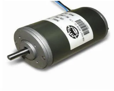
3.3.5 DC Generator
The dc generator of 500 rpm is used in this system which convert the mechanical input provided by mechanical arrangements into electrical output. The input to dc generator is fed by the rotation of shaft obtained from chain sprocket system.
A coil of wire rotating in a magnetic field produces a current which changes direction with each 180° rotation alternating current (AC), however many early uses of electricity required direct current (DC). In the first practical electric generators, called dynamos, the AC was converted into DC with a commutator, a set of rotating switch contacts on the armature shaft. The commutator reversed the connection of the armature winding to the circuit every 180° rotation of the shaft, creating a pulsing DC current. One of the first dynamos was built by Hippolyte piixi in 1832.
The dynamo was the first electrical generator capable of delivering power for industry. The Woolrich Electrical Generator of 1844, now in Thinktank, Birmingham Science Museum, is the earliest electrical generator used in an industrial process. It was used by the firm of Elkingtons for commercial electroplating.
The modern dynamo, fit for use in industrial applications, was invented independently by Sir Charles Wheatstone, Werner von Siemens and Samuel Alfred Varley. Varley took out a patent on 24 December 1866, while Siemens and Wheatstone both announced their discoveries on 17 January 1867, the latter delivering a paper on his discovery to the Royal Society.
The "dynamo-electric machine" employed self-powering electromagnetic field coils rather than permanent magnets to create the stator field. Wheatstone's design was similar to Siemens', with the difference that in the Siemens design the stator electromagnets were in series with the rotor, but in Wheatstone's design they were in parallel. The use of electromagnets rather than permanent magnets greatly increased
the power output of a dynamo and enabled high power generation for the first time. This invention led directly to the first major industrial uses of electricity. For example, in the 1870s Siemens used electromagnetic dynamos to power electric arc furnaces for the production of metals and other materials.
The dynamo machine that was developed consisted of a stationary structure, which provides the magnetic field, and a set of rotating windings which turn within that field. On larger machines the constant magnetic field is provided by one or more electromagnets, which are usually called field coils.
Fig -5
: 500RPM DC generator3.3.6 Battery
The output produced by dc generator is used to charge the battery and is used for various purposes.
[image:5.595.332.531.347.505.2]© 2018, IRJET | Impact Factor value: 6.171 | ISO 9001:2008 Certified Journal | Page 1372 Rechargeable batteries typically initially cost more than
disposable batteries, but have a much lower total cost of ownership and environmental impact, as they can be recharged inexpensively many times before they need replacing. Some rechargeable battery types are available in the same sizes and voltages as disposable types, and can be used interchangeably with them.
Fig -6: Battery
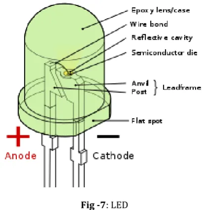
3.3.7 LED
The output produced by the dc generator and piezoelectric crystal can be realised effectively by applying LED at their terminals. The brightness of LED can be observed to determine the output voltage roughly.
A light-emitting diode (LED) is a two-lead semiconductor light source. It is a p–n junction diode that emits light when activated. When a suitable voltage is applied to the leads, electrons are able to recombine with electron holes within the device, releasing energy in the form of photons. This effect is called electroluminescence and the colour of the light (corresponding to the energy of the photon) is determined by the energy band gap of the semiconductor. LEDs are typically small (less than 1 mm2) and integrated optical components may be used to shape the radiation pattern.
Appearing as practical electronic components in 1962, the earliest LEDs emitted low-intensity infrared light. Infrared LEDs are still frequently used as transmitting elements in remote-control circuits, such as those in remote controls for a wide variety of consumer electronics. The first visible-light LEDs were also of low Intensity and limited to red. Modern LEDs are available across the visible, ultraviolet, and infrared wavelengths, with very high brightness Early LEDs were often used as indicator lamps for electronic devices, replacing small incandescent bulbs. They were soon packaged into numeric readouts in the form of seven-segment displays and were commonly seen in digital clocks. Recent developments have produced LEDs suitable for environmental and task lighting. LEDs have led to new
displays and sensors, while their high switching rates are useful in advanced communications technology.
LEDs have many advantages over incandescent light sources, including lower energy consumption, longer lifetime, improved physical robustness, smaller size, and faster switching. Light-emitting diodes are used in applications as diverse as aviation lighting, automotive headlamps, advertising, general lighting, traffic signals, camera flashes, and lighted wallpaper. They are also significantly more energy efficient and, arguably, have fewer environmental concerns linked to their disposal.
Fig -7: LED
3.3.8 ESP8266 Module
The output of dc generator and piezoelectric crystal can be monitored on real time basis using a Wi-Fi based ESP chip. The ESP sends the sensed output voltage on server using Wi-Fi network created by itself. The data send on server can be observed on laptops or mobiles by connecting to that Wi-Fi server and accessing the IP address.
[image:6.595.56.271.180.343.2] [image:6.595.328.533.247.460.2]© 2018, IRJET | Impact Factor value: 6.171 | ISO 9001:2008 Certified Journal | Page 1373 The ESP8266 Wi-Fi Module is a self co SOC with integrated
TCP/IP protocol stack that can give any microcontroller access to your Wi-Fi network. The ESP8266 is capable of either hosting an application or offloading all Wi-Fi networking functions from another application processor. Each ESP8266 module comes pre-programmed with a AT command set firmware, meaning, you can simply hook this up to your Arduino and get about as much Wi-Fi-ability as a Wi-Fi Shield offers. The ESP8266 module is an extremely cost effective board with a huge, and ever growing, community.
This module has a powerful enough on-board processing and storage capability that allows it to be integrated with the sensors and other application specific devices through its GPIOs with minimal development up-front and minimal loading during runtime. Its high degree of on-chip integration allows for minimal external circuitry, including the front-end module, is designed to occupy minimal PCB area. The ESP8266 supports APSD for VoIP applications and Bluetooth interfaces, it contains a self-calibrated following it to work under all operating conditions, and requires no external RF parts.
There is an almost limitless fountain of information available for the ESP8266, all of which has been provided by amazing community support. In the Documents section below you will find many resources to aid you in using the ESP8266, even instructions on how to transforming this module into an IOT (Internet of Things).
Fig -8
: EPS82663.4 Hardware Implementation
a) Mechanical Arrangement b) Spring
c) Rack-pinion d) Chain-sprocket e) Piezoelectric Crystal f) Shaft
g) DC Generator h) LED
i) ESP8266 j) Battery
4. ADVANTAGES & DISADVANTAGES
It is a non-conventional type of producing the energy. The existing source of energy such as coal, oil etc. may not be adequate to meet the ever increasing energy demands. These conventional sources of energy are also depleting and may be exhausted at the end of the century or beginning of the next century. Consequent sincere and untiring efforts shall have to be made by engineers in exploring the possibilities of harnessing energy from several non-conventional energy sources. This project is a one step to path of that way. The overall goal was to design the speed breaker System while keeping the engineering, producer and customer models in check. The reason why this feature was used more than all of the other features are because the other features would not have as much effect on the complete system. By changing the size and desirable price, weight and capacity can be realized. We used a survey to find out how the price, weight and capacity were scaled. Much was learned on how to and not to conduct a survey
4.1 Advantages
1. Require simple construction methods 2. Free from all types of pollutions 3. It is economical and easy to install 4. Maintenance cost is low.
5. No consumption of fossil fuel which is nonrenewable. 6. No manual work necessary during generation.
4.2 Disadvantages
1. Shafts are required to be mounted properly otherwise it creates balancing problem. 2. Mechanical vibration causes problem.
3. It will produce considerable amount of output mainly with heavy vehicles hence is not much suitable for light vehicles.
4. May get damaged in rainy season if not shielded properly.
5. Maintenance on regular basis is needed to check fault in either mechanical system or piezoelectric crystal.
[image:7.595.47.263.444.598.2]5. SCHEDULE FOR BALANCE WORK
Table -1: Schedule for Balance Work
Sr. No. Description Status Schedule 1 Discussion of
project topic Complete Aug 2017 2 Estimation of
project equipment Complete Sept 2017 3 Purchasing of
component Complete Oct 2017 4 Report writing for
© 2018, IRJET | Impact Factor value: 6.171 | ISO 9001:2008 Certified Journal | Page 1374 5 Assembling of
hardware Not Complete Dec 2017 6 Testing and
Finalization Not Complete Jan/Feb 2018
REFERENCES
[1] R.D.Sharma, S.Jain, K.Singh, "Growth rate of motor
vehicals in India", Journal of economics and social studies, Vol.I, 2011
[2] A.Padam Rao,"Power generation from speed breaker by
rack and ratchet method", International Journal of Current Engineering and Technology Issue-2, Februry,2014
[3] S. Srivastava, A. Asthana,"Produce electricity by the help
of speed breakers", Journal of engineering research and studies, Journal of Engineering Research and Studies, Vol.II, April-June,2011
[4] A. Mishra, P. Kale, International Journal of Engineering
and Science, Vol. II, March 2013.
[5] G.R.Prabu, G.Ethiraj, International Journal of Advanced
Research in Electrical, Electronics and Instrumental engineering, Innovation in Engineering and Technology (IJIET) Vol.2 Issue 2, March 2013.
[6] R.Gupta, S.Sharma, "A Revolutionary Technique of
Power Generation from speed breaker, International Journal of Engineering Research and technology, 2013.
[7] Amol Sheshrao Fawad, Air Compression and Electricity
Generation by Using Speed Breaker with Rack And Pinion Mechanism, International Of Modern Engineering Research (IJMER) Vol.5 Issue 1, January 2015.
[8] Ankita, Meenu Bala, Power Generation from Speed
Breakers, “International Journal Of Advance Research In Science and Engineering, 2013.
[9] Ashwathamah V Priyadharshini M., “International
Journal of Recent Research and Review,” Vol. I, ISSN 22778322, March 2012.
[10] “Every speed breaker is now a source of power”, IPCBEE