© 2017, IRJET | Impact Factor value: 5.181 | ISO 9001:2008 Certified Journal | Page 176
Effect of Infill and Mass Irregularity on RC Building under Seismic
Loading
Oman Sayyed
1, Suresh Singh Kushwah
2, Aruna Rawat
31
Post Graduate Student, Department of Civil Engineering, University Institute of Technology (RGPV), Bhopal, India
2Professor &
HOD,
Department of Civil Engineering, University Institute of Technology (RGPV), Bhopal, India
3
Asst. Prof. Department of Civil Engineering, University Institute of Technology (RGPV), Bhopal, India
---***---Abstract –
If there is a sudden change in mass, stiffness
and strength along the vertical or horizontal plane of a building then it may suffer serious damages due to seismic loading. Such a building which has an irregular distribution of mass, strength and stiffness along the building height can be termed as vertically irregular building. These irregularities cause deterioration of the building which leads to collapse. In this paper, the focus is made on the performance & behavior of regular & vertical irregular G+10 reinforced concrete (RC) buildings under seismic loading. Total nine building models having irregularity due to partial infill and mass irregularity are modeled & analyzed. Response spectrum analysis (RSA) is carried out for these building models for seismic zone V and medium soil strata as per IS 1893:2002 (part I). Seismic responses like storey displacement, storey drift, overturning moment, storey shear force, storey stiffness are obtained. By using these responses comparison is made between the regular and irregular building models. This study focuses on the effect of infill and mass irregularity on different floor in RC buildings. The results conclude that the brick infill enhances the seismic performance of the RC buildings and poor seismic responses are shown by the mass irregular building, therefore it should be avoided in the seismic vulnerable regions.Key words: Equivalent Diagonal Strut, Infill irregularity, Masonry infill, Mass irregularity, Response spectrum analysis, Vertical Irregular.
1. INTRODUCTION
In the past, a number of major earthquakes have uncovered the deficiency in buildings. This weakness causes deterioration of the building which leads to the collapse. This weakness mostly occurs due to the presence of irregularities in a building system. It has been observed that regular buildings perform better than irregular buildings under seismic loading. The irregularities in the buildings are present due to irregular distribution of mass, strength and stiffness along the height and plan of building. Mainly these irregularities are classified into two types as shown in Fig. 1 and the irregularity limits prescribed by IS 1893:2002 (part I) are given in Table 1.
[image:1.595.305.497.242.419.2]Fig.1: Detail of irregularities in RC buildings.
Table 1: Verticalirregularity limits prescribed by IS 1893:2002
Type of Vertical
Irregularity Prescribed Limits
Stiffness Irregularity - Soft Storey
A soft storey is one in which the lateral stiffness is less than 70 percent of that in the storey above or less than 80 percent of the average lateral stiffness of the three storeys above.
Stiffness Irregularity - Extreme Soft Storey
A extreme soft storey is one in which the lateral stiffness is less than 60 percent of that in the storey above or less than 70 percent of the average stiffness of the three storeys above.
Mass Irregularity
Mass irregularity shall be considered to exist where the seismic weight of any storey is more than 200 percent of that of its adjacent storeys.
Vertical Geometric Irregularity
Vertical geometric irregularity shall be considered to exist where the horizontal dimension of the lateral force resisting system in any storey is more than 150 percent of that in its adjacent storey. In-Plane Discontinuity in
Vertical Elements Resisting Lateral Force
An in-plane offset of the lateral force resisting elements greater than the length of those elements.
Discontinuity in Capacity-Weak Storey
A weak storey is one in which the storey lateral strength is less than 80 percent of that in the storey above.
Irregularities
Vertical irregularity
•Irregular distribution of stiffness, mass and strength along the height.
•Setback
Horizontal irregularity
•Irregular distribution of stiffness, mass and strength along the plan.
•Diaphragm discontinuity
•Re entrained corners
[image:1.595.307.568.451.731.2]© 2017, IRJET | Impact Factor value: 5.181 | ISO 9001:2008 Certified Journal | Page 177
2. LITERATURE REVIEW
The various research works which have been carried out on performance of infill and mass irregular buildings are as follows:
Tamboli and Karadi (2012) performed a seismic analysis using equivalent lateral force method for different RC frame building models that include bare frame, infilled frame and open first storey frame. They concluded that infilled frames should be preferred in seismic regions than the open first storey frame.
Shaikh and Deshmukh (2013) performed linear static & dynamic analysis on a G+10 vertically irregular building, as per IS 1893:2002 (part I) provisions. The building was modeled as a simplified lump mass model having stiffness irregularity at fourth floor. The results show that, a building structure with stiffness irregularity provides instability and attracts huge storey shear.
Hawaldar and Kulkarni (2015) considered G+12 storey building models with and without infill and carried out time history analysis for Bhuj and Koyna earthquake functions using ETABS 2013 software. They concluded that the displacement values for Bhuj function are higher than the displacement values for Koyna function and those for infilled buildings are less than without infilled buildings which suggest that as the infill stiffness increases the top storey displacement reduces.
Vijayan and Prakash (2016) analyzed a multi storied RC building of earthquake intensity III by time history analysis (THA) and the effects of seismic behavior on the building in terms of seismic responses such as storey displacement, storey drift and base shear of the structure was calculated. They concluded that building without any mass irregularities are the better structures for resisting seismic loads. If any mass irregularities exists that must be concentrated on bottom,to or top or anycentral areas of building.
Objectives of the present study are (i)to carryout response spectrum analysis (RSA) of various regular and irregular G+10 RC buildings as per IS 1893:2002 (part I) criteria using CSI ETABS 2015 software considering seismic zone V and medium soil strata for all the cases, (ii) to evaluate various seismic responses like storey displacement, storey drift, overturning moment, storey shear force, and storey stiffness of the regular and vertical irregular buildings and (iii) to make the comparison between the regular and irregular buildings on the basis of these responses.
3. METHODOLOGY
The study involves seismic analysis of various nine regular and irregular G+10 storey RC buildings. Two types of
vertical irregularities are considered namely irregularity due to partial infill and mass irregularity. The regular building (bare frame model) in both the cases are same. Changes in seismic responses due to the variation of irregularities along the height of the building have been studied. The plan and elevation of bare frame (model B) is given in Fig. 2 and Table 2 shows its structural details.
TABLE 2:Structural details of bare frame (model B)
Specification Structural Detail
No. of storeys G+10
Storey height 3 m
No. of bays in X and Y direction 3
Spacing of frame in X and Y direction 4 m
Grade of concrete M 25
Thickness of slab 0.125 m
Beam size 0.45 m × 0.30 m
Column size 0.45 m × 0.45 m
Thickness of Outer wall 0.23 m
Thickness of Inner wall 0.115 m
Poisson ratio of brick masonry 0.198
Modulus of elasticity of concrete 25×103 MPa
Modulus of elasticity of brick
masonry 4.125×10³ MPa
No. of mode used 30
Damping ratio 5%
Seismic zone V
Response reduction factor (R) 5
Soil type Medium
Zone factor (Z) 0.36
Importance factor ( I ) 1
© 2017, IRJET | Impact Factor value: 5.181 | ISO 9001:2008 Certified Journal | Page 178
3.1 Infill irregular buildings (partial infill)
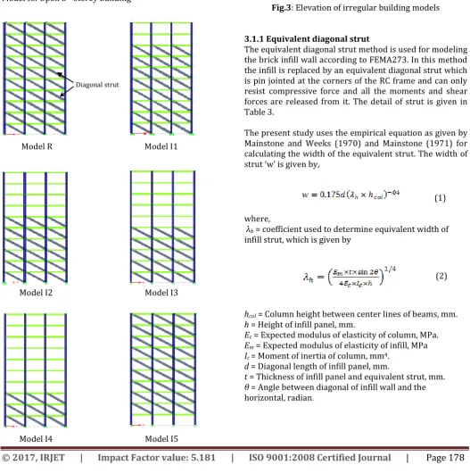
In this study eight RC G+10 storey buildings are considered as shown in Fig.3. Seismic responses of the buildings due to variation of infill along the height are calculated. The infill wall is modeled as a single equivalent diagonal strut pinned at both ends.
Model B: Bare frame Model R: Infilled building Model I1: Infill upto 8th storey
Model I2: Infill upto 6th storey
Model I3: Infill upto 5th storey
Model I4: Infill upto 3rd storey
Model I5: Open ground storey building Model I6: Open 5th storey building
Diagonal strut
Model R Model I1
Model I2 Model I3
Model I4 Model I5
Model I6
Fig.3: Elevation of irregular building models
3.1.1 Equivalent diagonal strut
[image:3.595.34.562.273.804.2]The equivalent diagonal strut method is used for modeling the brick infill wall according to FEMA273. In this method the infill is replaced by an equivalent diagonal strut which is pin jointed at the corners of the RC frame and can only resist compressive force and all the moments and shear forces are released from it. The detail of strut is given in Table 3.
The present study uses the empirical equation as given by Mainstone and Weeks (1970) and Mainstone (1971) for calculating the width of the equivalent strut. The width of strut ‘w’ is given by,
(1)
where,
λh = coefficient used to determine equivalent width of
infill strut, which is given by
(2)
hcol = Column height between center lines of beams, mm.
h = Height of infill panel, mm.
Ec = Expected modulus of elasticity of column, MPa.
Em = Expected modulus of elasticity of infill, MPa
Ic = Moment of inertia of column, mm4.
d = Diagonal length of infill panel, mm.
t = Thickness of infill panel and equivalent strut, mm. θ = Angle between diagonal of infill wall and the horizontal, radian.
© 2017, IRJET | Impact Factor value: 5.181 | ISO 9001:2008 Certified Journal | Page 179
Table -3:
Detail of diagonal strut
3.2. Mass irregular building
In present case the irregular model is same as regular model (bare frame model B) but refuge area is provided at fourth storey and eight storey of the building and other geometry remains the same as shown in Fig. 2 and Table 2.
Loading due to refuge area is 15 kN/m2.
Model B: Regular bare frame
Model M: Mass irregularity at 4th and 8th floor
3. RESULTS AND DESCUSSIONS
3.1 Infill irregular building (partial infill)
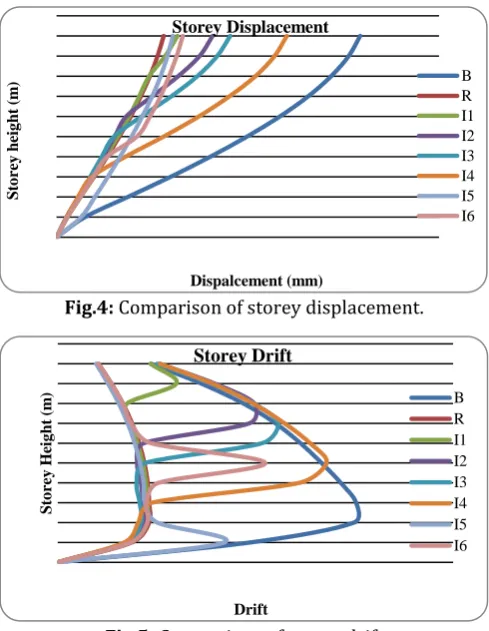
After performing response spectrum analysis, responses at each storey are shown in Figs. 4 to 8 along the storey height.
Fig.4: Comparison of storey displacement.
Fig.5: Comparison of storey drift
.
Fig.6: Comparison of overturning moment.
Fig.7: Comparison of storey shear force.
Fig.8: Comparison of storey stiffness.
Storey displacement is maximum in case of bare frame (B) and minimum in case of infilled frame (R). In the storeys which are not infilled, a sudden extreme change in the slope of the displacement curve has been observed as shown in Fig.4. Storey drift is maximum in case of bare frame (B). A sudden extreme change in the drift is observed due to absence of infill as shown in Fig. 5. The overturning moment and storey shear is maximum in case of infilled frame (R) and it decreases as the percentage of infill in the building decreases as shown in Figs. 6 and 7. The stiffness is maximum in case of infilled frame (R) and it decreases due to absence of infill as shown in Fig. 8.
Wall h
(mm) d (mm)
Θ (degrees)
λh w
(mm) Size of diagonal strut in mm Outer
wall 3000 5000 36.86 0.97 570 ×230mm 570mm Inner
wall 3000 5000 36.86 0.97 570 ×115mm 570mm
S to re y h ei g h t (m ) Dispalcement (mm) Storey Displacement B R I1 I2 I3 I4 I5 I6 St or ey he ig ht (m )
Shear force (KN)
Storey Shear Force
[image:4.595.309.557.249.588.2] [image:4.595.39.284.423.739.2]© 2017, IRJET | Impact Factor value: 5.181 | ISO 9001:2008 Certified Journal | Page 180
3.2 Mass irregular building
The analyses of models for mass irregular buildings are evaluated and the responses are shown in Figs. 9 to 13. The top node displacement in case of mass irregular building is greater than that of the regular building. But in lower storeys it is approximately same as that of regular building as shown in Fig. 9.
Fig.9: Comparison of storey displacement.
The storey drift is greater in case of mass irregular building in the intermediate storeys, but in top and bottom storeys it is same as that of regular building as shown in Fig.10.
Fig.10: Comparison of storey drift.
Fig.11: Comparison of overturning moment.
Fig.12: Comparison of storey shear force.
The overturning moment and storey shear force has been found maximum in ground storey and it decreases towards the top of the building. The mass irregular building has more overturning moment and storey shear force in lower storeys as compare to regular building, but in top storeys it is approximately same as that of regular building as shown in Figs. 11 and 12, respectively.
Fig.13: Comparison of storey stiffness.
Fig.13 shows that due to mass irregularity the stiffness of the irregular building gets marginally affected in the top storeys. But in the bottom storeys, stiffness of mass irregular building is exactly same as that of regular building.
St
ore
y
he
ight
(
m
)
Dispalcement (mm)
Storey Displacement
B M
St
ore
y
he
ight
(
m
)
Drift Storey Drift
B
St
ore
y
he
ight
(
m
)
Shear force (kN)
Storey Shear Force
B
M
S
to
re
y
h
eig
h
t
(m
)
Stiffness (kN/m) Storey Stiffness
B
M
St
ore
y
he
ight
(
m
)
Moment kN-m
Overturning Moment
© 2017, IRJET | Impact Factor value: 5.181 | ISO 9001:2008 Certified Journal | Page 181
4. CONCLUSIONS
The performance and behavior of regular and vertical irregular for infill and mass irregularities G+10 RC buildings are studied under seismic loading and following conclusions are made:
1. The displacement results show that the storey displacement is maximum in case of bare frame (B) and minimum in case of infilled frame (R). The storey drift is maximum in case of bare frame (B) and it suddenly increases in the storeys having no infill. Therefore, infilled building frame should be preferred in the seismic prone areas as compared to the bare building frame.
2. Infilled frame (R) has maximum overturning moment and storey shear force in the lower storeys. The overturning moment and storey shear is maximum in case of infilled frame (R) and it decreases as the percentage of infill in the building decreases. The result shows that the presence of brick infill increases the stiffness and strength of the RC buildings.
3. The mass irregular building undergoes more displacement as compare to regular building in the top storeys. But in lower storeys the displacement in mass irregular building is approximately same as that of regular building. The storey drift is more in case of mass irregular building in the intermediate storeys, but in top and bottom storeys it is same as that of regular building.
4. The overturning moment and storey shear force is maximum in ground storey in case of mass irregular building and it decreases towards the top of the building. A marginal effect on stiffness in the top storeys of the building due to mass irregularity has been observed. It can be concluded that in seismic regions poor performance is observed in case of mass irregular buildings. Therefore, for resisting seismic loads buildings without any mass irregularities are the better buildings.
REFERENCES
[1] R.J Mainstone and G.A.Weeks (1970). “The Influence of
Bounding Frame on the Racking Stiffness and Strength of Brick Walls”, 2nd International Brick Masonry
Conference, Stoke-on-Trent, UK.
[2] R.J. Mainstone (1971). “On the Stiffness and Strength
of Infill frames”, Institution of Civil Engineers, Supplement IV, pp. 57-90.
[3] FEMA-273 (1997). “NEHRP Guidelines for Seismic
Rehabilition of Buildings”, Building Seismic Safety Council, Federal Emergency Management Agency, Washington, D.C, USA.
[4] H.R.Tamboli and U.N. Karadi (2012.), “Seismic
Analysis of RC Frame Structure with and without Masonry Infill Walls”, Indian Journal of Natural Sciences, Vol 3, Issue 14, pp. 1137-1148.
[5] A.R. Shaikh and G.Deshmukh (2013) “Seismic
Response of Vertically Irregular RC Frame with Stiffness Irregularity at Fourth Floor”, International Journal of Emerging Technology and Advanced Engineering, Vol 3, Issue 8, pp. 377-385
[6] J.C.Hawaldar and D. K. Kulkarni (2015), “Earthquake
Analysis of a G+12 Storey Building with and without Infill for Bhuj and Koyna Earthquake Functions”, International Research Journal of Engineering and Technology, Vol 02, Issue 05,pp. 525-531
[7] A.Vijayan and A. Prakash (2016), “Study on Seismic
Analysis of Multi Storied Reinforced Concrete Building with Mass Irregularities,” International Journal of Science and Research, Vol 5, Issue 7,pp.1196-1198
[8] IS 1893:2002 (Part 1). “Indian Standard Criteria for