COMPARATIVE STUDY OF ANNULAR RAFT FOUNDATION & SOLID
CIRCULAR RAFT FOUNDATION FOR DIFFERENT DIAMETER OF WATER
TANK
Yogesh Rana
1, Abbas Jamani
21,2 Department of Structural Engineering
1Student of L.J. Institute of Engineering and Technology 2Assistant Professor, L.J. Institute of Engineering and Technology
---***---Abstract -
Storage reservoirs and overhead tank are used to store water, liquid petroleum, petroleum products and similar liquids. The force analysis of the reservoirs or tanks is about the same irrespective of the chemical nature of the product. All tanks are designed as crack free structures to eliminate any leakage. Water is the prime necessity for survival. Liquid storage tanks are used extensively by municipalities and industries for storing water, inflammable liquids and other chemicals. Thus Water tanks are very important for public utility and for industrial structure.This study attempted the achievement of some measure of the best practical solution, that is, the optimum design of elevated reinforced concrete water tanks for a specified performance in which the major objectives are covers the degree of effectiveness of the geometric shapes for the functional requirement, to assess the possible cost implications of each of the choices and to eventually generate Microsoft Excel Spreadsheet Design Programs as a tool for the rather quick assessment of various tank capacities. The main aim of this dissertation is to done the foundation analysis of circular water tank and cost comparison for different type of foundation required like annular raft and solid circular type raft & parametric study about time period, hydrodynamic pressure, and seismic pressure respective to H/D ratio.
Key Words: circular water tank, raft foundation
soft soil & medium soil, Seismic pressure, Hydrodynamic pressure, Time period, Staad pro V8i.
1. INTRODUCTION
Human civilization has been established long ago. For its development and progress “Civil Engineering” has come into existence, then after there is tremendous continuous progress. In our day-to-day life we see many structures around us, which are the gift of Civil Engineering to human society. There are three basicneeds of human namely food, clothes and shelter. The civil engineering satisfy shelter need directly. Further, for the progress of any country good infra-structural facility is required, which is provided by civil engineering. Transportation and Communication facilities plays very important role in improving country’s economic growth rate. There are many special civil engineering
structures apart from buildings for example Highways, Bridges, Tunnels, Dams, High-rise Towers, Historical Monuments, Cooling Towers, Nuclear power plants and many more. Elevated Water Tank is also one of them. Reservoir is a common term applied to liquid storage structure and it can be below or above the ground level. Reservoirs below the ground level are normally built to store large quantities of water whereas those of overhead type are built for direct distribution by gravity flow and are usually of smaller capacity
.
Analysis and design of such tanks are independent of chemical nature of product. In order to avoid leakage and to provide higher strength concrete of grade M25 and above is recommended for liquid retaining structures.Present study primarily focused on To study the effect of a number of column, batter of column on performance of staging. In addition to the vertical loads is also subjected to horizontal forces. Both these forces produce axial tension or compression in columns as well as moment and shear force on column section. Here attempt is made to find out optimum diameter of staging based on 'No-Tension' in column. Lateral load also affect stability of foundation. Here attempt is made to find out optimum diameter of annular raft footing and solid circular raft footing based on 'No-Tension' in foundation and fulfil all stability requirement of foundation including 'No Uplift. comparative study like hydrodynamic pressure, seismic pressure, time period with respect to H/D ratio of different diameter and cost analysis by using annular raft and circular raft foundation for soft soil and medium soil.
2. METHODOLOGY
In the present paper consider different diameter of container resting on bottom slab & circular staging on periphery maintain H/D ration in 0.02 increment, where H = water height & D = diameter of tank. Seismic analysis of staging is considered as per IS code 1893 (II) & concrete design by using staad pro v8i.design of top slab & bottom slab by using staad pro V8i plate model. Design of annular raft & circular raft as per code (IS 11089 -1984) & also referred book punamia & Jain.
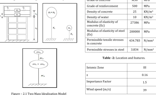
surface is subjected to horizontal earthquake ground motion, tank wall and liquid are subjected to horizontal acceleration. The liquid in the lower region behaves like a mass that is rigidly connected to the tank wall. This mass is termed as impulsive liquid mass, which, accelerates along with the wall and induces impulsive hydrodynamic pressure on tank wall and on base. The liquid mass in the upper region of tank undergoes sloshing motion. This mass is termed as convective liquid mass and exerts convective hydrodynamic pressure on wall and base. For representing these two masses and in order to include the effect of their hydrodynamic pressure in analysis, spring mass model is adopted for ground-supported tanks and two-mass model for elevated tanks. In spring mass model convective mass (mc) is attached to the tank wall by the spring having stiffness Kc, whereas impulsive mass (mi) is rigidly attached to tank wall For elevated tanks two-mass model is considered, which consists of two degrees of freedom system. Spring mass model can also be applied on elevated tanks, but two-mass model idealization is closer to reality. The spring mass model for elevated tank is as shown in fig.2.1.
The response of the two-degree of freedom system can be obtained by elementary structural dynamics. However, for most of elevated tanks it is observed that both the time periods are well separated. Hence, the two-mass idealization can be treated as two uncoupled single degree of freedom system as shown in fig.2.1. The mass (ms) shown in fig.2.1 is the structural mass and shall comprise of mass of tank container and one-third mass of staging as staging will acts like a lateral spring. Mass of container comprises of mass of roof slab, container wall, gallery if any, floor slab, floor beams, ring beam, circular girder, and domes if provided.
Figure – 2.1 Two Mass Idealization Model
Where,
mi = Impulsive mass mc = Convective mass
ms = Mass of container of elevated tank and one third of staging
Kc = spring stiffness of convective mode Ks = Lateral stiffness of tank staging
hc = Height at which resultant of convective pressure on wall is located from the bottom of tank wall
hi = Height at which resultant of impulsive hydrodynamic pressure on wall is located from the bottom of tank wall hi* = Height at which resultant of impulsive hydrodynamic pressure on wall and base is located from the bottom of tank wall
hc* = Height at which resultant of convective pressure on wall and base is located from the bottom of tank wall
2.1 GENERAL CONSIDERATION
Different capacity of circular water tank selected for study purpose. Twelve models are prepare respective soft soil and medium soil where SBC considered 100 KN/m2 & 200 KN/m2.Primary data considered for design mentioned below.
Table -1: Material and permissible stresses considered for design.
Grade of concrete M30 MPa
Grade of reinforcement 500 MPa
Density of concrete 25 KN/m3
Density of water 10 KN/m3
Modulus of elasticity of
concrete (Ec) 27386 MPa
Modulus of elasticity of steel
(Es) 200000 MPa
Permissible tensile stresses
in concrete 434.783 N/mm
2
[image:2.595.37.537.477.781.2]Permissible stresses in steel 3.834 N/mm2
Table -2: Location and features.
Seismic Zone III
z 0.16
Importance Factor 1.5
Terrain Category 3
Class A
Type of Soil Soft & Medium soil
Response Red. Factor 2.5
K1 1.06
K2 1
2.3 ANALYSIS AND CALCULATIONS
The design of overhead circular Water Tank is carried out using the Staad pro V8i. The design is carried out as per relevant analysis procedures combined with Indian Standard Codes of Practices. The water tank top & bottom slab are designed by Limit stress method. The foundation forces at the level of safe bearing capacity are also evaluated and then manually solid circular raft and annular raft foundation design can be done for diff diameter. The software also gives the shape description of the tank and keeping various parameters, one can change the governing parameter to get the optimum result and safe design with economy.
For analysis purpose considered different type of diameter respective to no of column. In these research maintain H/D ratio. Calculate weight of each component like container in empty & full condition, top slab, bottom slab, staging etc.
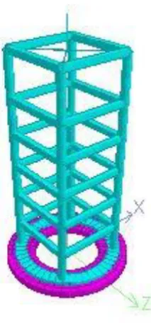
[image:3.595.104.211.511.740.2]Evolution of seismic analysis and design of column & bracing used by staad pro V8i. Here 50kl water tank model shown below.
Figure – 2.2 Model geometry of staging part and plate model with annular raft in staad pro V8i.
Size of component considered in design and analysis of different diameter of circular water tank like diameter of container, column size, no of bracing and its size, parameter and size of annular raft and circular raft are mentioned below table – 3.
Table -3: Size and component adopted for different diameter of container, staging, bracing, annular raft and
circular raft.
Component Parameter Capacity (lit.)
50 KL
CO
NT
A
INE
R
Dia of tank inner (m) 6
Thk of wall (m) 0.2
Height of water (m) 1.90
Free board (m) 0.4
total height (m) 2.30
H/D ratio 0.32
T
O
P S
LA
B
&
B
O
T
TO
M
SL
A
B
Top Slab Thk (m) 0.175
Dia of top slab (m) 6.4 Bottom Slab Thk (m) 0.275 Dia of bottom slab (m) 8.8
ST
A
G
ING
No of staging 4
Staging height (m) 12
Staging dia (m) 0.45
Degree 90
B
RA
CI
NG No of Bracing 5
Size of bracing 0.3 x 0.4
Length of bracing 4.384
SBC 100 KN/m2
A
NNU
LA
R
RA
FT
Inner Dia (m) 4.4
outer dia (m) 8
Thk of Raft (m) 0.400 to 0.250
CI
RC
U
LA
R
RA
FT
Inner Dia (m) 0
outer dia (m) 9.3
Thk of Raft (m) 0.250 to 0.150
SBC 200 KN/m2
A
NNU
LA
R
RA
FT
Inner Dia (m) 5.2
outer dia (m) 7.2
Thk of Raft (m) 0.300 to 0.150
CI
RC
U
LA
R
RA
FT
Inner Dia (m) 0
outer dia (m) 9.3
Component Parameter Capacity (lit.) 130 KL CO NT A INE R
Dia of tank inner (m) 8
Thk of wall (m) 0.2
Height of water (m) 2.75
Free board (m) 0.45
total height (m) 3.20
H/D ratio 0.34
T O P S LA B & B O T TO M S LA
B Top Slab Thk (m) 0.2
Dia of top slab (m) 8.4 Bottom Slab Thk (m) 0.275 Dia of bottom slab
(m) 10.8
ST
A
G
ING
No of staging 6
Staging height (m) 12
Staging dia (m) 0.5
Degree 60
B
RA
CI
NG No of Bracing 5
Size of bracing 0.3 x 0.4
Length of bracing 4.1
SBC 100 KN/m2
A NNU LA R RA FT
Inner Dia (m) 5.2
outer dia (m) 11.2
Thk of Raft (m) 0.500 to 0.350
CI RC U LA R RA FT
Inner Dia (m) 0
outer dia (m) 12.3
Thk of Raft (m) 0.350 to 0.250
SBC 200 KN/m2
A NNU LA R RA FT
Inner Dia (m) 6.7
outer dia (m) 9.7
Thk of Raft (m) 0.450 to 0.200
CI RC U LA R RA FT
Inner Dia (m) 0
outer dia (m) 12.3
Thk of Raft (m) 0.350 to 0.250
Component Parameter Capacity (lit.)
270 KL CO NT A INE R
Dia of tank inner (m) 10
Thk of wall (m) 0.2
Height of water (m) 3.60
Free board (m) 0.5
total height (m) 4.10
H/D ratio 0.36
T O P S LA B & B O T TO M SL A B
Top Slab Thk (m) 0.25
Dia of top slab (m) 10.4 Bottom Slab Thk (m) 0.3 Dia of bottom slab (m) 12.8
ST
A
G
ING
No of staging 8
Staging height (m) 12
Staging dia (m) 0.5
Degree 45
B
RA
CI
NG No of Bracing 5
Size of bracing 0.3 x 0.4
Length of bracing 3.903
SBC 100 KN/m2
A NNU LA R RA FT
Inner Dia (m) 6.2
outer dia (m) 14.2
Thk of Raft (m) 0.500 to 0.350
CI RC U LA R RA FT
Inner Dia (m) 0
outer dia (m) 15.3
Thk of Raft (m) 0.350 to 0.250
SBC 200 KN/m2
A NNU LA R RA FT
Inner Dia (m) 8.2
outer dia (m) 12.2
Thk of Raft (m) 0.500 to 0.300
CI RC U LA R RA FT
Inner Dia (m) 0
outer dia (m) 15.3
Component Parameter Capacity (lit.) 830 KL CO NT A INE R
Dia of tank inner (m) 14
Thk of wall (m) 0.25
Height of water (m) 5.60
Free board (m) 0.5
total height (m) 6.10
H/D ratio 0.4
TO P SL AB & BO TT OM Top Slab Thk (m) SL AB 0.35
Dia of top slab (m) 14.5 Bottom Slab Thk (m) 0.45 Dia of bottom slab (m) 16.9
ST
A
G
ING
No of staging 12
Staging height (m) 12
Staging dia (m) 0.5
Degree 30
B
RA
CI
NG No of Bracing 5
Size of bracing 0.3 x 0.4
Length of bracing 3.688
SBC 100 KN/m2
A NNU LA R RA FT
Inner Dia (m) 5.95
outer dia (m) 22.55
Thk of Raft (m) 0.850 to 0.700
CI RC U LA R RA FT
Inner Dia (m) 0
outer dia (m) 21.4
Thk of Raft (m) 0.650 to 0.450
SBC 200 KN/m2
A NNU LA R RA FT
Inner Dia (m) 10.75
outer dia (m) 17.75
Thk of Raft (m) 0.700 to 0.500
CI RC U LA R RA FT
Inner Dia (m) 0
outer dia (m) 21.4
Thk of Raft (m) 0.650 to 0.450
Component Parameter Capacity (lit.)
1275 KL CO NT A INE R
Dia of tank inner (m) 16
Thk of wall (m) 0.3
Height of water (m) 6.70
Free board (m) 0.6
total height (m) 7.30
H/D ratio 0.42
T O P S LA B & B O T TO M SL A B
Top Slab Thk (m) 0.45
Dia of top slab (m) 16.6 Bottom Slab Thk (m) 0.55 Dia of bottom slab (m) 19
ST
A
G
ING
No of staging 14
Staging height (m) 12
Staging dia (m) 0.55
Degree 25.71
B
RA
CI
NG No of Bracing Size of bracing 0.35 x 0.45 5
Component Parameter Capacity (lit.)
485 KL CO NT A INE R
Dia of tank inner (m) 12
Thk of wall (m) 0.2
Height of water (m) 4.55
Free board (m) 0.575
total height (m) 5.13
H/D ratio 0.38
T O P S LA B & B O T TO M SL A B
Top Slab Thk (m) 0.3
Dia of top slab (m) 12.4 Bottom Slab Thk (m) 0.4 Dia of bottom slab (m) 14.8
ST
A
G
ING
No of staging 10
Staging height (m) 12
Staging dia (m) 0.5
Degree 36
B
RA
CI
NG No of Bracing 5
Size of bracing 0.3 x 0.4
Length of bracing 3.77
SBC 100 KN/m2
A NNU LA R RA FT
Inner Dia (m) 6
outer dia (m) 18.4
Thk of Raft (m) 0.750 to 0.500
CI RC U LA R RA FT
Inner Dia (m) 0
outer dia (m) 18.4
Thk of Raft (m) 0.550 to 0.450
SBC 200 KN/m2
A NNU LA R RA FT
Inner Dia (m) 9.7
outer dia (m) 14.7
Thk of Raft (m) 0.6 to 0.4
CI RC U LA R RA FT
Inner Dia (m) 0
outer dia (m) 18.4
Length of bracing 3.627
SBC 100 KN/m2
A
NNU
LA
R
RA
FT
Inner Dia (m) 4.3
outer dia (m) 28.3
Thk of Raft (m) 1.200 to 0.750
CI
RC
U
LA
R
RA
FT
Inner Dia (m) 0
outer dia (m) 24.5
Thk of Raft (m) 0.950 to 0.650
SBC 200 KN/m2
A
NNU
LA
R
RA
FT
Inner Dia (m) 11.3
outer dia (m) 21.3
Thk of Raft (m) 1.000 to 0.650
CI
RC
U
LA
R
RA
FT
Inner Dia (m) 0
outer dia (m) 24.5
Thk of Raft (m) 0.900 to 0.650
3. RESULTS AND ANALYSIS
After study and analysis of different diameter of water tank respectively annular raft foundation and circular raft foundation perform following result respectively each parameter like time period, base moment, base shear, hydrodynamic pressure, seismic pressure and analysis of cost estimation.
Parametric study and result for time period of impulsive mode and convective mode.
CASE – I: Tank in full condition:-
Capacity H/D Ti TC
50 KL 0.32 0.878 2.823
130 KL 0.34 0.933 3.203
270 KL 0.36 0.992 3.55
485 KL 0.38 1.143 3.851
830 KL 0.40 1.252 4.125
1275 KL 0.42 1.346 4.379
CASE – II: Tank in empty condition:-
Capacity H/D Ti TC
50 KL 0.32 0.803 NA
130 KL 0.34 0.81 NA
270 KL 0.36 0.825 NA
485 KL 0.38 0.924 NA
830 KL 0.4 0.977 NA
1275 KL 0.42 1.056 NA
Tank in full condition Tank in Empty condition
H/D shear Base moment Base shear Base moment Base
0.32 109.236 32.768 98.366 12.714
0.34 189.112 112.452 161.524 13.186 0.36 304.704 281.232 247.322 15.074 0.38 454.604 562.974 354.72 15.143 0.4 643.636 1051.214 486.145 15.417 0.42 981.161 1804.381 751.964 15.604
Parametric study and result of base shear and base moment for soft soil (SBC = 200 KN/m2).
Tank in full condition Tank in Empty condition
H/D shear Base moment Base shear Base moment Base
0.32 89.062 26.714 79.677 12.714
0.34 153.955 91.53 132.156 13.186
0.36 248.404 229.151 201.427 13.667 0.38 371.23 459.894 289.484 14.061 0.4 529.242 857.143 397.216 14.719 0.42 807.895 1473.578 613.444 15.241
Parametric study and behavior of hydrodynamic pressure and seismic pressure respectively H/D ratio in soft soil (SBC = 100 KN/m2).
Capacity H/D Hydrodynamic pressure pressure Seismic
50 KL 0.32 2.514 11.641
130 KL 0.34 3.302 13.407
270 KL 0.36 4.068 15.074
485 KL 0.38 4.753 15.143
830 KL 0.4 5.595 15.417
1275 KL 0.42 6.491 15.604
Parametric study and behavior of hydrodynamic pressure and seismic pressure respectively H/D ratio in soft soil (SBC = 200 KN/m2).
Capacity H/D Hydrodynamic pressure pressure Seismic
50 KL 0.32 2.225 9.503
130 KL 0.34 2.966 10.916
270 KL 0.36 3.699 12.298
485 KL 0.38 4.395 12.357
830 KL 0.4 5.235 12.495
1275 KL 0.42 6.12 12.828
3.1 COST ANALYSIS
C),Page 43 to 53.(GUJARAT WATER SUPPLY AND SEWERAGE BOARD).
Cost comparison of annular raft and circular raft for 100 KN/m2 (Soft soil).
Capacity Annular raft Circular raft
50 KL ₹ 944,870 ₹ 987,678
130 KL ₹ 1,776,154 ₹ 1,798,172
270 KL ₹ 2,659,357 ₹ 2,666,777
485 KL ₹ 4,817,682 ₹ 4,972,296
830 KL ₹ 7,907,680 ₹ 7,698,238
1275 KL ₹ 14,455,964 ₹ 12,326,264
Cost comparison of annular raft and circular raft for 200 KN/m2 (Medium soil).
Capacity Annular raft Circular raft
50 KL ₹ 866,031 ₹ 981,186
130 KL ₹ 1,513,452 ₹ 1,775,405
270 KL ₹ 2,292,868 ₹ 2,650,888
485 KL ₹ 3,645,373 ₹ 4,969,293
830 KL ₹ 5,446,555 ₹ 7,426,623
1275 KL ₹ 9,250,402 ₹ 11,935,489
4. CONCLUSIONS
and study after safe design of circular water tank following conclusion drawn mentioned below respective to annular raft & solid circular raft in soft soil And medium soil and comparative study of different parameter.
1. As per results and analysis H/D ratio vs time period in convective mod and impulsive mode in empty and full condition linearly increase as shown in graph.
2. As per results and analysis H/D ratio vs hydrodynamic pressure and seismic pressure in soft soil (100 KN/m2) and Medium soil (200 KN/m2) and full condition linearly increase as shown in graph.
3. When diameter increase and number of column increase the different movement shown in soft and medium soil like in soft soil (100 KN/m2) up to 12 m diameter of 485 kl capacity of tank resting on 10 circular column annular raft is safe and economical in cost more than solid circular raft and in design more than 12 m diameter solid circular raft is safe and economical in cost shown in graph.
4. In medium soil (200 KN/m2) diameter increase annular raft is safe and economical in cost more than solid circular raft shown in graph.
ACKNOWLEDGEMENT
I wish to express my deep sense of gratitude to my guide prof. Farhan Vahora for his valuable guidance and motivation throughout my project work.
I also want to thank our coordinate prof. Abbas jamani for his cooperation and generous help.
REFERENCES
[1] Sajjad Sameer U and Sudhir K. Jain, “Lateral Load Analysis of Frame Staging for Elevated Water Tanks”, Structural Engineering, ASCE, May- 1994, Vol-120, Pg-1375.
[2] S.C.Dutta, S.K.Jain, and C.V.R.Murty, “Alternate Tank Staging Configuration with reduced Torsional Vulnerability”, Soil Dynamics and Earthquake Engineering, Science Direct, Dec-1999, Vol-19, Pg-199.
[3] Sameer, S. U., and Jain, S. K., 1994, “Lateral load analysis of frame staging for elevated water tanks”, Structural Engineering, ASCE, Vol.120, No.5, Pg. - 1375.
of Elevated Water Tank”, International Journal of Scientific & Engineering Research, Volume 4, Issue 6, June-2013, ISSN 2229-5518,
[5] Syed Saif Uddin, "Seismic analysis of liquid storage tanks", International Journal of Advanced Trends in Computer Science and Engineering, Vol.2, No.1, Pages: 357 – 362 (2013).
[6] Draft Indian standard, "criteria for earthquake resistant design of structures: Part 2 liquid retaining tanks (revision of is 1893(part 2))
[7] M. V. Waghmare, S.N.Madhekar, " Behaviour of elevated water tank under sloshing effect", International journal of advanced technology in civil engineering, issn: 2231 – 5721, volume-2, issue-1, 2013
[8] Nankar aniket,navale shrikant,palve Gaurav ,”Evaluation of seismic force for elevated water tank” International research journal of engineering and technology, Volume 2,issue 7,oct – 2015,ISSN:2395-0056
[9] IS: 3370-2009, concrete structures for storage of Liquids - code of practice, part 1, general requirements.
[10]IS : 3370-2009, Concrete structures for storage of liquids - code of practice, Part2, reinforced concrete structures
[11]IS : 11682-1985, Criteria for design of rcc staging for overhead water tank
[12]Bureau of indian standards criteria for design of rcc staging for overhead water tanks (First Revision of IS 11682), June-2011
[13]STAAD Pro., Reference Manual
[14]Reinforced Concrete Vol.-2 by Dr. H. J. Shah, Charotar publication
[15]A Manual of limit state design by Variyani and Radhaji
[16]R.C.C. Designs (Reinforced concrete structures) by Dr. B. C. Punmia, Er. Ashok kumar Jain, Dr. Arun K. Jain, Laxmi publication.