© 2017, IRJET | Impact Factor value: 5.181 | ISO 9001:2008 Certified Journal | Page 2545
Comparative Study of RC Structures with Different Types of Infill Walls
with Effect of SSI by Pushover Analysis
Basavaraj M. Malagimani
1, Swapnil B. Cholekar
2, Hemant L. Sonawadekar
31
Post-Graduate Student, Dept. of Civil Engineering,
KLE Dr. M. S. Sheshgiri College of Engineering and Technology, Belagavi, India
2,3
Professor, Dept. of Civil Engineering,
KLE Dr. M. S. Sheshgiri College of Engineering and Technology, Belagavi, India
---***---Abstract - Brick is the most frequently used material for
building construction. In India it is common practice to construct reinforced concrete buildings with unreinforced infill. Infill panels have traditionally been made of heavy rigid materials such as red bricks or concrete blocks. Now in India more light weight and flexible infill materials such as light weight bricks (AAC) or hollow blocks are to be used as masonry infill material in reinforced concrete buildings. On the performance of RC buildings, it has been recognized that infill materials have significant effect.In the present study an effort is made to study the behavior of RC frame structure using conventional bricks, CC blocks, hollow blocks and light weight bricks infill. Linear static and non-linear static pushover analysis has been carried out for fixed and flexible support in different types of soil condition, to know the effect of earthquake loading. The various results such as base shear, top storey displacement, natural period and pushover results are compared to know the suitable infill material in seismic prone zones. From the results obtained the light weight brick system gives better performance than the other infill materials.
Key Words
:
Fixed support structure, flexible
support structure, linear analysis, Pushover
analysis, Soil Structure Interaction.
1. INTRODUCTION
In present construction the reinforced cement concrete is most widely used material in the world. A bare frame of R.C. buildings consist of many horizontal components and vertical components. Horizontal components such as beams and slabs and vertical components such as columns and walls which are under side of slabs. All these components which are cast at a time called monolithic and this type of construction is known as monolithic R.C. frame building or each component might a chance to be casted apart and gathered at the site is known as pre cast R.C. frame structures.
The opposition of the lateral load and gravity load that is dead load and live load which can contributed by the combined action of slab, beams and columns. Satisfactorily
ductile property shall be provided for the R.C. structures which are contributed at the earthquake zones or they ought to at least possess the capacity with support specific deformity under that movement for overwhelming staking states.
In vertical plane the walls are constructed with beams and columns at the required locations in structures. The most commonly used brick infill is conventional burnt clay brick masonry. Along with this or combination of light weight bricks such as autoclaved aerated concrete bricks, hollow concrete blocks are also used.
1.1 Conventional Brick Infill Structures
In the world most commonly R.C. building with infill of brick masonry is used including in the region of earthquake zone. Reinforced concrete building with brick infill walls are analyzed and designed as bare frame neglecting strength contribution and infill stiffness. Moreover the infill acts along with the response of the structures infill behaviour is different from that anticipated for building without infill.
The lateral force resisting capacity and stiffness of structure can be increase by infill also up to a same level of response. The structures initial period is decreased because of increased initial stiffness of structures. Infill with brick masonry is verge to brittle failure, for evaluation of seismic. The infill wall modeling should be proper within the structure is beneficial and also to reduce the damage and consequences for proper solution of retrofit.
1.2 Autoclaved Aerated Concrete (AAC) Block Infill
Structures
© 2017, IRJET | Impact Factor value: 5.181 | ISO 9001:2008 Certified Journal | Page 2546 reduced by the use of AAC material and which intern
decreases the seismic design base shear of the structure.
Today AAC material is revolutionary precast and offers distinctive of high strength and durability, lower in weight unmatched ability and superior features of green ecology. In other part of country the AAC materials is used as replacing ordinary clay bricks and fly ash brick since the material in the state of art green ecological building. The panels and blocks are adopted in all types of walls, internal or external, load bearing and non-load bearing walls etc.
2. MODELING
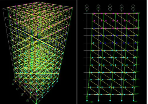
In the present study, four different types infill materials viz, conventional brick, cement concrete block, hollow block and light weight brick is taken into consideration. The building models with different types infill materials is modeled and analyzed using the computer software ETABS-2009 and the results are compared
[image:2.595.295.550.56.240.2].
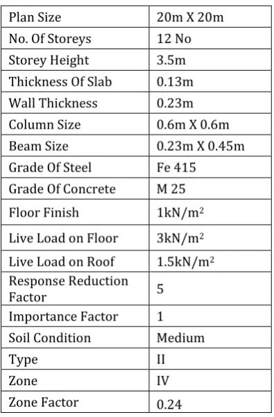
Table -2.1: Analysis Data
Plan Size 20m X 20m
No. Of Storeys 12 No
Storey Height 3.5m
Thickness Of Slab 0.13m
Wall Thickness 0.23m
Column Size 0.6m X 0.6m
Beam Size 0.23m X 0.45m
Grade Of Steel Fe 415 Grade Of Concrete M 25
Floor Finish 1kN/m2
Live Load on Floor 3kN/m2
Live Load on Roof 1.5kN/m2
Response Reduction
Factor 5
Importance Factor 1
Soil Condition Medium
Type II
Zone IV
Zone Factor 0.24
2.1 Modelling of Infill Wall as a Equivalent Diagonal Strut Member
According to Smith proposal the width of equivalent diagonal strut is given by
Effective width,
Where and are given by
, Where
W = Width of equivalent strut Em = Elastic modulus of material
Ef = Elastic modulus of frame
t = Thickness of infill wall L = Length of infill wall Ic = Moment of Inertia of
Ib = Moment of inertia of beam
Calculation of width of Equivalent Diagonal Strut for light weight bright
Beam size = 0.23m X 0.45m Column size = 0.6m X 0.6m
Young’s Modulus of light weight brick = 1840MPa Young’s Modulus of concrete =25000MPa
Moment of Inertia =
Moment of Inertia of beam Ib= 0.00175 m4
Moment of Inertia of column Ic= 0.01080 m4
Ө = tan-1 = 34.73°
αh = 3.709 m
αl = 2.668 m
w = = 2.284 m
[image:2.595.63.261.365.666.2]Similarly width of other infill materials are calculated and tabulated as bellow
Table -2.2Equivalent Diagonal Strut
Type of
infill Concrete Block Hollow Block Conventional Brick Light Weight Brick Young’s
Modulus
(MPa) 3500 3000 3500 1840
width
(m) 1.954 2.022 1.954 2.284
[image:2.595.296.570.502.753.2]© 2017, IRJET | Impact Factor value: 5.181 | ISO 9001:2008 Certified Journal | Page 2547
Fig. 2.3 Elevation of flexible support building.
2.2 Soil Structure Interaction
All the buildings which are situated on ground, act like cantilever which is fixed at base and free at top. The soil structure interaction in the present study considered to understand the behaviour of 3D frame structure which is prone to earthquake forces for different types of soil conditions along with different types of infill such as conventional brick, CC blocks, hollow blocks and light weight bricks.
“The process in which the response of the soil media influences the motion of the structure and motion of the structure influences the response of the soil medium is termed as Soil Structure Interaction”.
Spring stiffness values are calculated from FEMA-356 page No. 136 after designing footing.
Table -2.3 Computation of Soil Stiffness from FEMA 356
DOF Stiffness of foundation at surface
Translation
along x - axis Kx= Translation
along y - axis Ky= Translation
along z- axis Kz= Rocking
about x - axis Kxx=
Rocking
about y- axis Kyy= Torsion
about z - axis Kzz=
Table 2.4 Computation of Soil Stiffness in Medium soil
DOF Cement Concrete Block
Hollow
Block Conventional Brick
Light Weight Brick
Kx 639024.20 607852 584473 562074
Ky 639024.20 607852 584473 562074
Kz 828701.20 788277 757958 715724
Kxx 2963929.05 2550998 2267828 2028773 Kyy 2572690.42 2214266 1968474 1760975 Kzz 4007232.08 3448949 3066103 2827298
3. RESULTS AND DISCUSSION
The various observations obtained from the analysis of conventional brick, Cement Concrete block, hollow block and light weight brick infill by linear and nonlinear cases with Soil Structure Interaction. The observations such as base shear, natural period, and displacement and pushover results are discussed in brief in medium soil.
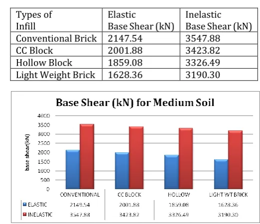
[image:3.595.298.559.460.685.2]3.1 Base Shear for medium soil
Table 3.1 Base Shear (kN)
Types of
Infill Elastic Base Shear (kN) Inelastic Base Shear (kN) Conventional Brick 2147.54 3547.88
CC Block 2001.88 3423.82
Hollow Block 1859.08 3326.49
Light Weight Brick 1628.36 3190.30
Fig. 3.1 Comparison of Base Shear (kN).
© 2017, IRJET | Impact Factor value: 5.181 | ISO 9001:2008 Certified Journal | Page 2548 compared to elastic base shear. The conventional brick infill
gives higher value since it is having large mass and stiffness. The light weight brick infill gives lower value since it is having large mass and stiffness
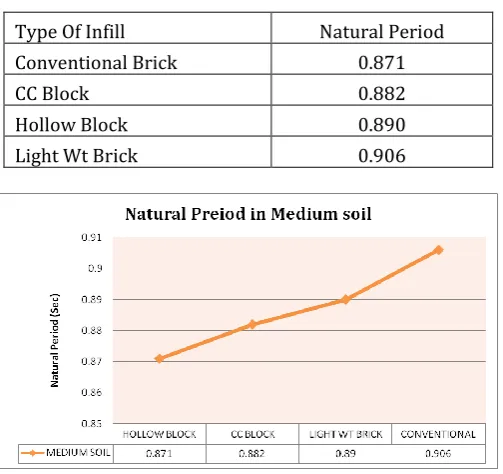
[image:4.595.307.568.59.387.2]3.2 Natural Period for medium soil
Table 3.2 Natural Period (Sec)
Type Of Infill Natural Period
Conventional Brick 0.871
CC Block 0.882
Hollow Block 0.890
Light Wt Brick 0.906
Fig. 3.2 Comparison of Natural Period (Sec).
Table 3.2 shows the natural period value for the first mode that is the fundamental mode of various infill models. Fig 3.2 shows the variation of natural period. From the above results the natural period for the light weight brick model is higher as compared with other infill models, it can be seen from the results that model with conventional brick is stiffer than the model with other infill model. The light weight brick infill model is more flexible than the other infill models.
3.3 Displacement for medium soil
Table 3.3 Displacement (mm) values
Storey Conventional
Brick
Light Weight
Brick
Cement Concrete
Block Hollow Block
12 13.2 12.9 12.8 12.6
11 12.5 12.3 12.2 12
10 11.7 11.5 11.4 11.2
9 10.8 10.7 10.5 10.4
8 9.9 9.7 9.6 9.5
7 8.9 8.7 8.6 8.5
6 7.8 7.7 7.6 7.5
5 6.8 6.6 6.6 6.5
4 5.7 5.5 5.6 5.5
3 4.7 4.4 4.6 4.5
2 3.7 3.4 3.6 3.5
1 2.7 2.2 2.6 2.5
base 0.1 0.1 0.1 0.1
Fig. 3.3 Comparison of Displacement (mm)
Table 3.3 shows the displacement values of different types of infill material. And fig 3.3 gives the comparison plot between conventional brick, light weight brick, CC block and hollow brick infill. Here the conventional brick model gives the larger value as comparing with other type infill model. Since base shear for conventional brick model is more and lateral forces over the structure is more and hence more will be the displacement value as compared with other infill material.
3.4 Nonlinear Static Pushover Results
Table 3.4 Capacity Spectrum parameters in Medium Soil
Parameter Conventional Bricks Blocks CC Hollow Blocks Weight Light Bricks Base Shear
(kN) 3547.88 3423.8 3326.4 3190.2
Top Roof Displacement (m)
0.373 0.352 0.335 0.306
Spectral Acceleration Sa(m/s)
0.069 0.074 0.078 0.086
Spectral
[image:4.595.37.289.199.436.2]© 2017, IRJET | Impact Factor value: 5.181 | ISO 9001:2008 Certified Journal | Page 2549 Sd(m)
Effective Time Period Teff(s)
4.069 3.831 3.633 3.315
Effective
Damping 0.161 0.161 0.16 0.159
Table 3.4 shows the nonlinear static pushover results for various infill models by capacity spectrum method in medium soil condition. The inelastic base shear of flexible support in medium soil is lesser than the inelastic base shear of hard soil.
By observing the values in four different infill model the time period goes on decreasing hence spectral acceleration goes on increasing from conventional brick model to light weight brick model. The light weight brick model produces lesser base shear as compared to hollow block, CC block and conventional bricks.
4.6.5 Hinge Results in Medium Soil
[image:5.595.30.294.99.173.2]Fig 4.3 shows the various hinge formation of flexible support in medium soil during earthquake. From hinge steps observations, the first hinge formation takes place in beams and in column the hinges start to develop as the seismic load goes on increasing. From the theoretical background, the performance of the structure should not go beyond the immediate occupancy level and life safety level of performance.
Fig 3.4 Hinge formation in conventional brick model
The various hinge formation of conventional brick model and CC brick model are studied. From the hinge results, the top storeys are having flexural hinges, the middle storeys are having immediate occupancy level hinges and most of the bottom storeys are having life safety hinges. The more life safety hinges are formed in columns of the ground storey because of absence of infill. And very few collapse prevention hinges are formed in columns of bottom storey.
The various hinge formation of hollow block model and light weight brick model are studied. From the hinge results, the top storeys are having flexural hinges, the middle storeys are having immediate occupancy hinges and bottom storeys are having more life safety hinges. It shows that the structure has damaged and before re-occupying it has to be retrofitted.
3. CONCLUSIONS
The present study of analysis makes an effort to understand the effect of brick infill ( conventional brick infill, concrete block infill, hollow block infill and light weight brick infill ) and SSI on the behaviour of RC structues. The analysis is been carried out using Non-linear analysis, with code specified design responce spectrum, using ETABS. The results of the study lead to the following conclussions.
1) From the observations larger the mass of the structure larger will be the seismic force acting on the structure. Hence the light weight brick model gives the lesser seismic force as compared with hollow block, CC block and conventional brick. Hence it is better to use light weight bricks in seismic prone zones.
2) For conventional brick infill model it has been observed that base shear, lateral forces and storey shear are large as compared with other infill models. Hence design with conventional brick infill is non-conservative.
3) The light weight brick infill model is having significantly smaller base shear as compared with other infill models which results in decrease in reinforcement to resist member forces, hence economy in construction can be achieved.
4) The study shows that the effect of SSI may appreciably influence the natuaral periods as well as base shear of building structure. These are the parameters, which affect the seismic response of the building frames. Thus evaluation of these parameters without conducting SSI cause significant error in seismic design.
5) The study shows that, light weight brick infill gives lesser seismic force as compared with other infills. Therefore using light weight brick infill the seismic design is more conservative as compared with other infill materials.
6) The influence of SSI in general decreases the base shear (increase the natural period) which the influence of brick infill in general increases the base shear (decreases the natural period), hence to some extent they are compensatory and however the influence of brick infill is very predominant. 7) Immediate occupancy hinges are formed in the light
[image:5.595.37.288.466.642.2]© 2017, IRJET | Impact Factor value: 5.181 | ISO 9001:2008 Certified Journal | Page 2550
REFERENCES
1. Ajay Patre and Laxmikant Vairagade, “Analysis of High Rise Building Using Light Weight Infill Blocks and Conventional Bricks”, Journal Of Information, Knowledge And Research In Civil Engineering, ISSN: 0975-6744, 2016.
2. Ms. Rajashri A.Deshmukh, Dr. P.S. Pajgade, “A Study of Effect of Infill Material on Seismic Performance of RC Buildings”, International Journal of Engineering Sciences & Research Technology, ISSN: 2277-9655, 2015.
3. Munde P.K, Magarpatil H.R, “Seismic Response of RC Framed Masonry Infilled Buildings With Soft First Storey”, International Journal of Engineering Research & Technology, ISSN: 2278-0181, 2012. 4. Er. Puneet Sharma, Er. Ankit, Er. Ismit Pal Singh,
“Soil Structure Interaction Effect on an Asymmetrical R.C.Building with Shear Walls”, IOSR Journal of Mechanical and Civil Engineering, ISSN: 2278-1684, 2014.
5. M Roopa, H. G. Naikar and Dr. D. S. Prakash, “Soil Structure Interaction Analysis on a RC Building With Raft Foundation Under Clayey Soil Condition”, International Journal of Engineering Research & Technology, ISSN: 2278-0181, 2015.
6. D. Gauney and E. Aydin, “The Nonlinear Effect of Infill Walls Stiffness to Prevent Soft Storey Collapse of RC Structures”, The Open Construction and Building Technology Journal, 2012.
7. Applied Technology Council, ATC-40: Seismic Evaluation and Retrofit of Concrete Buildings volume 1.1996: California.
8. IS1893-2002, Indian Standard Criteria for Earthquake Resistant Design of Structure, 5th
revision, Bureau of Indian Standards.
9. Federal Emergency Management Agency, FEMA-356: Pre-stndard and Commentary for the Seismic Rehabilitation of . 2000: Washington DC.
10. Dr. Vinod Hosur, “Earthquake – Resistant Design of Building Structures”, Wiley Precise Textbook.
BIOGRAPHIES
Basavaraj M. Malagimani
Post-Graduate Student,
Department of Civil Engineering, KLE Dr.M.S.Sheshgiri College of Engineering and Technology, Belagavi, India-
Prof. Swapnil B. Cholekar
M.Tech (Structural Engineering), B.E (Civil),
Assistant Professor,
Department of Civil Engineering, KLE Dr.M.S.Sheshgiri College of Engineering and Technology, Belagavi, India-
Prof. Hemant L. Sonawadekar
M.Tech (Structural Engineering), B.E (Civil),
Assistant Professor,