A Monthly Double-Blind Peer Reviewed Refereed Open Access International e-Journal - Included in the International Serial Directories. GE-International Journal of Engineering Research (GE-IJER) ISSN: (2321-1717)
82 | P a g e
GE-International Journal of Engineering Research
Vol. 4, Issue 8, August 2016 IF- 4.721 ISSN: (2321-1717) © Associated Asia Research Foundation (AARF) PublicationWebsite: www.aarf.asia Email : [email protected] , [email protected]
COMPARATIVE HORIZONTAL RETAINING FORCE OF
CONVENTIONAL AND INTERLOCKING CONCRETE BLOCK
RETAINING WALL
Krishpersad Manohar1, Roshan Panchoo2
1
Mechanical and Manufacturing Engineering Department, The University of the West Indies, St. Augustine, Trinidad
2
Ronblock International Company Limited, 11A Gosine Street, Poole, Rio Claro, Trinidad
ABSTRACT
Comparative horizontal retaining force tests were conducted between regular and
interlocking concrete block free standing retaining wall sections 1.63 m (64”) high and 2.44 m (96”) wide. The centrally loaded horizontal force was applied using the 793 Series MTS
linear Actuator. The force and corresponding wall deflection was logged at one second
intervals until structural wall failure. Experimental results indicated that the free standing interlocking block retaining wall section resisted a higher horizontal force ranging from
32.5% to 66.3% when compared with the regular concrete block wall section. The
interlocking block wall section showed an average of 46.5% higher horizontal retaining force
then the regular block wall. There were no significant difference in the wall deflection at
which structural failure occurred for the regular concrete block wall and the interlocking
concrete block wall.
KEYWORDS – Retaining wall, Interlocking blocks, Concrete blocks, Horizontal force.
1. INTRODUCTION
In general landscaping retaining walls are structures designed and constructed to resist
the lateral pressure of soil and keep it in place when there is a desired change in ground
elevation that exceeds the angle of repose of the soil [1]. There are different designs of
retaining walls suited for respective applications [2]. However, the most important
consideration in proper design and installation of retaining walls is to ensure that the wall
A Monthly Double-Blind Peer Reviewed Refereed Open Access International e-Journal - Included in the International Serial Directories. GE-International Journal of Engineering Research (GE-IJER) ISSN: (2321-1717)
83 | P a g e
downslope movement of the retained material creates lateral earth pressure behind the wall
[3]. The magnitude of this pressure depends on the angle of internal friction, the cohesive
strength of the retained material, as well as the direction and magnitude of movement the
retaining structure undergoes [4].
Some special purpose walls are designed to retain water, however, in general it is
important to have proper drainage behind the wall in order to limit the pressure due to water
retention. Accommodation of drainage materials or design consideration will reduce or
eliminate the hydrostatic pressure and improve the stability of the material behind the wall
[5]. Without a pressure-relief system, the weight of the water in the soil could crack, or even
buckle, the wall. Drystone retaining walls are normally self-draining. Weep holes
incorporated in the wall along the top of the first course can channel some of the water out.
Other designs include a plastic drainpipe covered with gravel [6].
Concrete blocks are commonly available material that are ideal for building small
scale retaining walls to hold back the soil after digging into a slope for a pathway, patio, or
other small projects. Retaining walls constructed from standard blocks are generally the same
as freestanding block walls. However, since the retaining wall has a horizontal force to resist
it must be stronger than freestanding walls [7]. To improve the wall strength a rebar is insert
in the footing of the wall which is accommodated in the core of the blocks. Usually at every
three blocks high intervals the cores around the rebar are filled with mortar from the bottom
to top [8]. The conventional concrete blocks has a square edge and during wall construction
the blocks are placed together with a layer of mortar between to hold it in place [9]. In this
study, an interlocking concrete block design that do not require mortar between consecutive
horizontal blocks was used to construct a retaining wall section. The horizontal retaining
wall force was tested and compared to a conventional block retaining wall section under
similar test conditions.
2. EXPERIMENTALPROCEDURE
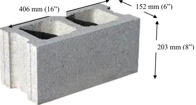
Two retaining wall sections with different concrete block designs were constructed for comparative testing. The first wall design was constructed with the regular commercial
concrete block of dimensions 152 mm x 203 mm x 406 mm (6”x8”x16”) as shown in Figure
A Monthly Double-Blind Peer Reviewed Refereed Open Access International e-Journal - Included in the International Serial Directories. GE-International Journal of Engineering Research (GE-IJER) ISSN: (2321-1717)
[image:3.595.182.511.36.213.2]84 | P a g e
Figure 1. Regular conctete block
A 13 mm (½”) steel rod was centrally installed in the vertically core of each block. The
Cores of the blocks wall were filled with pliable concrete at three block height intervals.
During the core filling process the concrete was prodded to ensure proper and complete
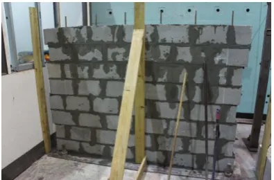
filling of the cores. Figure 2 shows a wall section under construction. Three test wall
sections 1.63 m (64”) high and 2.44 m (96”) wide was constructed. Each test wall section
was allowed to cure for seven days before testing.
Figure 2. Regular concrete test wall under construction
The second wall design was constructed with the interlocking concrete block of dimensions 152 mm x 203 mm x 406 mm (6”x8”x16”) as shown in Figure 3.
152 mm (6”)
[image:3.595.200.397.387.530.2]A Monthly Double-Blind Peer Reviewed Refereed Open Access International e-Journal - Included in the International Serial Directories. GE-International Journal of Engineering Research (GE-IJER) ISSN: (2321-1717)
[image:4.595.170.461.36.179.2]85 | P a g e
Figure 3. Interlocking conctete block
A 13 mm (½”) steel rod was centrally installed in the vertically core of each interlocking
block. The Cores of the interlocking blocks wall were filled with pliable concrete at three
block height intervals. During the core filling process the concrete was prodded to ensure
proper and complete filling of the cores. Three test wall sections 1.63 m (64”) high and 2.44 m (96”) wide was constructed. Figure 4 shows a completed interlocking block wall section
after construction. Each test wall section was allowed to cure for seven days before testing.
Figure 4. Completed interlocking block wall section with rebar
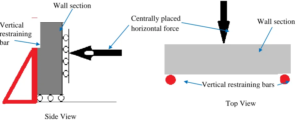
The retaining wall sections were ‘simply-supported’ vertically at both ends. The
distance between the vertical restraining bars was 2 m. The base of the walls rested freely on
a smooth 18mm thick steel plate to simulate a free standing wall section. To simulate the
force exerted from the backfill material a centrally placed horizontal force was applied to the
wall section. Figure 5 shows a schematic of the test set-up. 406 mm (16”) 203 mm (8”)
[image:4.595.199.397.333.463.2]A Monthly Double-Blind Peer Reviewed Refereed Open Access International e-Journal - Included in the International Serial Directories. GE-International Journal of Engineering Research (GE-IJER) ISSN: (2321-1717)
[image:5.595.71.544.61.252.2]86 | P a g e
Figure 5. Schematic of wall section test set-up.
Comparative retaining force tests were conducted on the six cured retaining wall
sections. The apparatus used to apply the horizontal force was the 793 Series MTS Actuator.
This linear actuator measured simultaneously the horizontal force (N) (± 0.1N) and the
respective wall deflection (mm) (±0.01 mm). Once the test started the apparatus was
automatically controlled by a computer that recorded the force and corresponding wall
deflection data at one second intervals. Each test proceeded until the wall failed.
3. RESULTS
Each cured specimen of the free standing retaining wall sections, simply-supported
vertically at both ends, was tested to determine the horizontal retaining force. The specimens
were subjected to a centrally located horizontal force using the 793 Series MTS Actuator
apparatus and the variation of horizontal force with horizontal wall displacement was
recorded automatically by the computer at one second intervals until the wall section was broken. The test results for the three wall sections constructed with the regular concrete
blocks with 13 mm vertical rebar in the core filled with concrete are shown below in Figures
6 to 8. The maximum retaining force and corresponding displacement for each test are noted. Side View
Top View Vertical
restraining bar
Vertical restraining bars Wall section
Wall section Centrally placed
A Monthly Double-Blind Peer Reviewed Refereed Open Access International e-Journal - Included in the International Serial Directories. GE-International Journal of Engineering Research (GE-IJER) ISSN: (2321-1717)
[image:6.595.96.497.36.272.2]87 | P a g e
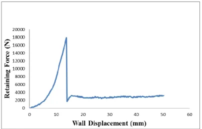
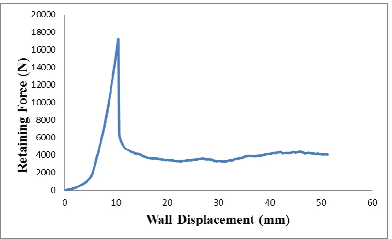
Figure 6. Regular Concrete Block Wall with Vertical Steel rebar concrete filled core – Sample 1.
The test results shown on Figure 6 indicated a Maximum retaining force 15600.59 N at a wall deflection of 12.1681 mm. Structural failure occurred beyond this point.
Figure 7. Regular Concrete Block Wall with Vertical Steel rebar concrete filled core – Sample 2.
[image:6.595.96.501.381.639.2]A Monthly Double-Blind Peer Reviewed Refereed Open Access International e-Journal - Included in the International Serial Directories. GE-International Journal of Engineering Research (GE-IJER) ISSN: (2321-1717)
[image:7.595.97.502.61.308.2]88 | P a g e
Figure 8. Regular Concrete Block Wall with Vertical Steel rebar concrete filled core – Sample 3.
The test results shown on Figure 8 indicated a Maximum retaining force 17149.73 N at a wall deflection of 10.4950 mm. Structural failure occurred beyond this point.
The average retaining force for the regular concrete block wall with vertical steel rebar and concrete filled core was calculated as 16862 N at an average wall deflection of 12.2 mm.
A Monthly Double-Blind Peer Reviewed Refereed Open Access International e-Journal - Included in the International Serial Directories. GE-International Journal of Engineering Research (GE-IJER) ISSN: (2321-1717)
[image:8.595.100.500.37.269.2]89 | P a g e
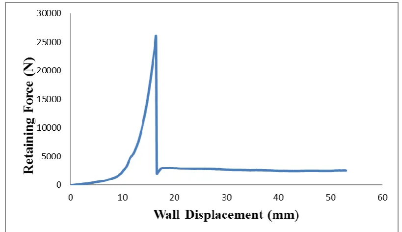
Figure 9. Interlocking Concrete Block Wall with Vertical Steel rebar concrete filled core – Sample 1.
The test results shown on Figure 9 indicated a Maximum retaining force 23637.81 N at a wall deflection of 11.6664 mm. Structural failure occurred beyond this point.
Figure 10. Interlocking Concrete Block Wall with Vertical Steel rebar concrete filled core – Sample 2.
[image:8.595.92.502.369.605.2]A Monthly Double-Blind Peer Reviewed Refereed Open Access International e-Journal - Included in the International Serial Directories. GE-International Journal of Engineering Research (GE-IJER) ISSN: (2321-1717)
[image:9.595.96.498.36.274.2]90 | P a g e
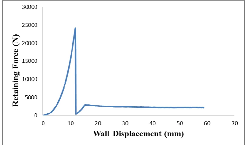
Figure 11. Interlocking Concrete Block Wall with Vertical Steel rebar concrete filled core – Sample 3.
The test results shown on Figure 11 indicated a Maximum retaining force 24059.28 N at a
wall deflection of 11.8328 mm. Structural failure occurred beyond this point.
The average retaining force for the interlocking concrete block wall with vertical steel rebar
and concrete filled core was calculated as 24546 N at an average wall deflection of 13.3 mm.
4. DISCUSSION
Regular concrete blocks are convenient and easily available for the construction of
retaining wall structures. The practice of using vertical rebar with concrete filled core are the
norm for concrete block retaining walls. The use of mortar during construction is to hold the
blocks in place and ensure proper alignment. The mortar joining is not a structural force
bearing attachment. The interlocking block design accommodated for load bearing joint
where the blocks interlocked. At this junction the adjacent pre-cast concrete blocks make
direct contact which would resist horizontal force loading.
The experiments were designed to simulate a horizontal force loading on a free
standing retaining wall section as shown in Figure 5. The test results for the three regular
concrete block wall sections ranged between 15600 N to 17835 N with an average horizontal
retaining force of 16862 N at a mean wall deflection of 12.2 mm at the center of the wall. The
A Monthly Double-Blind Peer Reviewed Refereed Open Access International e-Journal - Included in the International Serial Directories. GE-International Journal of Engineering Research (GE-IJER) ISSN: (2321-1717)
91 | P a g e
25942 N with an average horizontal retaining force of 24546 N at a mean wall deflection of
13.3 mm at the center of the wall.
All three interlocking retaining wall section showed a higher horizontal retaining
force than the three regular retaining wall sections. From the test results the minimum
difference in horizontal retaining force between the regular and interlocking block walls was
5802 N or 32.5%. The maximum difference in horizontal retaining force between the regular
and interlocking block walls was 10342 N or 66.3%. The difference between the mean
horizontal retaining force between the regular and interlocking block walls was 7684 N or
45.6%. Structural failure on the average for all the walls was 12.7 mm. There were no
significant difference in the structural failure deflection between the regular concrete block
wall and the interlocking concrete block wall.
5. CONCLUSIONS
The interlocking concrete block design forms a horizontal retaining force load bearing
joint between adjacent blocks. The free standing interlocking block retaining wall section
showed a higher horizontal retaining wall force ranging from 32.5% to 66.3% when
compared with the regular concrete block wall section. On the average, the interlocking
block wall section showed a 46.5% higher horizontal retaining force then the regular block
wall. On the average, structural failure under horizontal force loading occurred at about 12.7
mm deflection for both the interlocking and regular concrete block wall sections.
REFERENCES
[1] F.D. Ching, R.S. Faia, and P. Winkel, Building Codes Illustrated: A Guide to
Understanding the 2006 International Building Code, 2nd ed., (New York, NY:
Wiley, 2006).
[2] J. Ambrose, Simplified Design of Masonry Structures, 70-75,(New York: John
Wiley and Sons, Inc., 1991).
[3] M. Crosbie and D. Watson, Time-Saver Standards for Architectural Design, (New
York, NY: McGraw-Hill, 2005).
[4] Commercial Installation Manual for Allan Block Retaining Walls, 13, 2011.
Accessed 22 August 2016. Available:
A Monthly Double-Blind Peer Reviewed Refereed Open Access International e-Journal - Included in the International Serial Directories. GE-International Journal of Engineering Research (GE-IJER) ISSN: (2321-1717)
92 | P a g e
[5] K. Terzaghi, Large Retaining Wall Tests, Engineering News Record, 112, 1934,
136-140.
[6] J.D. Carpenter, Handbook of landscape architectural construction, Washington DC,
Landscape Architecture Foundation, 1976.
[7] Q.Q Sayyed and M.G. Shaikh, Articulated hollow concrete masonry blocks for
earth-retaining structures, International Journal of Engineering Research &
Technology, 4(4), 2015. 315-317.
[8] Boral MASONRY,Masonry Design Guide,south australia BOOK 2, 2007. Accessed
22 August 2016. Available:
http://www.boral.com.au/masonry-design-guide/pdf/BOR11999_S_ Manual_Bk2.pdf
[9] S. Ahmad, S.Hussain, M. Awais, M. Asif, H. Muzamil, R. Ahmad and S. Ahmad, To
study the behavior of interlocking of masonry units/blocks, IOSR Journal of
Engineering, 4(3), 2014, 2278-8719.
Journal Papers
1. K Nunjal, J. Adachi, and N. mill, Impact of FDI on Economy, International Journal of
Management, 18(2), 1998, 112-116.
Note that the journal title, volume number and issue number are set in italics.
Books
2. R.E. Moore, Interval analysis (Englewood Cliffs, NJ: Prentice-Hall, 1966).
Note that the title of the book is in lower case letters and italicized. There is no comma following the
title. Place of publication and publisher are given.
Chapters in Books
3. P.O. Bishop, Neurophysiology of binocular vision, in J.Houseman (Ed.), Handbook of
physiology, 4 (New York: Springer-Verlag, 1970) 342-366.
Note that the place of publication, publisher, and year of publication are enclosed in brackets. Editor
of book is listed before book title.
Thesis
4. D.S. Chan, Theory and implementation of multidimensional discrete systems for signal