International Journal of Emerging Technology and Advanced Engineering
Website: www.ijetae.com (ISSN 2250-2459, Volume 2, Issue 7, July 2012)1
Alleviation of Downstream Impediments of a Passive Optical
Network through Implementation of a Distributed Architecture
1
ASM Delowar Hossain,
2M. Kouar,
3M. Ummy,
4M. Razani
1,2,3,4 Department of Electrical Engineering Technology, New York City College of Technology,
City University of New York, NY, USA. Abstract— In this work, we examine the downstream
impediments of centralized Ethernet passive optical networks supporting LAN emulation [inter-Optical Network Units communication(ONU)]. The available downstream bandwidth in the centralized scheme is reduced due to LAN emulation and upstream bandwidth allocation functions. The reduction in available downstream bandwidth results in degraded downstream performance. To address this problem, we implement a LAN capable distributed ring architecture, where Optical Line Terminal is relieved from the burden of upstream bandwidth allocation and inter-ONU communication. Consequently, this increases the available downstream bandwidth and thereby enhancing downstream performance in terms of queuing delay, utilization, and packet loss ratio.
Keywords— Distributed Network, Passive Optical Network (PON), Ethernet PON, Access Network, Dynamic Bandwidth Allocation.
I. INTRODUCTION
Passive Optical Network (PON) technology, especially Ethernet PON (EPON), is a feasible solution for next-generation broadband access networks. A PON connects a group of Optical Network Units (ONUs) located at the subscriber premises to an Optical Line Terminal (OLT) located at the service provider’s facility. Traffic from an OLT to an ONU is called ―downstream‖, and traffic from an ONU to an OLT is called ―upstream‖ [1–7]. In the downstream direction, an EPON operates as a broadcast and select network. The OLT houses N number of queues, each corresponding to an ONU. Incoming traffic is first sorted according to destination ONU addresses and then accepted into the corresponding queues. The OLT divides available downstream bandwidth among the queues and allocates transmission timeslots. The OLT then broadcasts frames from a queue (corresponding to a destination ONU) in its allocated timeslot. An ONU accepts the broadcasted frame, matching its Medium Access Control (MAC) address to the frame destination address. The upstream operation is more involved in the typical centralized architecture; the OLT is required to perform an additional function of arbitrating among the ONUs for sharing upstream bandwidth.
In order to facilitate the implementation of upstream bandwidth allocation schemes, the OLT and ONUs exchange control messages, namely, the REPORT and the GATE messages. These control messages are defined by the IEEE 802.3ah task force through the development of a Multi-Point Control Protocol (MPCP) [2]. A REPORT message is sent by an ONU to an OLT informing it about its bandwidth requirements. Upon receiving a REPORT, the OLT passes the message to the OLT’s DBA module to perform the bandwidth allocation computation. The OLT then grants the ONU a transmission time slot by sending a GATE message indicating the start time and the duration of such a time slot. Then the ONUs transmit upstream traffic as per allocated timeslot.
PONs are traditionally deployed as centralized tree topologies; they have several inherent drawbacks, including i) an inefficient upstream control plane due to centralization at the OLT, ii) the inability to support a truly shared Local Area Network (LAN) capability (inter-ONU communication) among the (inter-ONUs in the upstream direction and iii) the first two drawbacks result in degraded downstream performance due to wastage of needed bandwidth [4]. This work focuses on the third issue (downstream performance), while the other two issues were detailed in our previous work[4].
Firstly, due to centralized control plane at OLT, the upstream operation requires frequent generation of REPORT and GATE messages. This function overburdens the OLT and consumes bandwidth unnecessarily, thereby hindering the network performance. Specifically, the GATE messages consumes downstream bandwidth, causing poor performance in downstream direction as detailed in Section A.
International Journal of Emerging Technology and Advanced Engineering
Website: www.ijetae.com (ISSN 2250-2459, Volume 2, Issue 7, July 2012)2
The alternate feasible solution of a standard upper layer shared LAN emulation technique, which requires the use of bridges/routers at the OLT to redirect LAN traffic back to the ONUs [7], consumes downstream bandwidth as well as over burdens OLT.
This technique is simple and effective but hinders downstream performance by consuming downstream transmission bandwidth and increasing end-to-end delay of LAN and original downstream traffic (Section B).
Among the recent research contributions pertaining to EPON downstream bandwidth allocation schemes [8-11], there was a LLID (end user) based solution that supports delay sensitive downstream traffic [8] and another scheme improving downstream burst mode traffic performance [9]. All these solutions (addressing various downstream issues) are within the framework of centralize architecture, which has inherent limitations [4,10] as discussed above. To date, virtually no significant solution has been proposed to address the centralized downstream impediments. This work, which extends our previous work [10], proposes a solution to the two above-mentioned impediments to downstream performance. We present a downstream Dynamic Bandwidth Allocation (DBA) scheme over a decentralized ring architecture (which inherently supports private networking capability), where the OLT is relieved of the burden of upstream bandwidth allocation and LAN traffic re-routing. The main characteristic of the proposed scheme is that it supports a fully distributed upstream control plane among the ONUs for ONU–ONU communication (LAN connectivity) as well as upstream access to the OLT [4]. Specifically, it utilizes a fully distributed Time Division Multiple Access (TDMA) arbitration scheme in which the OLT is excluded from the arbitration process. In the proposed decentralized scheme, the ONUs exchange signaling and control information concerning their queue statuses and their transmission needs amongst themselves (REPORT messages). Then, the ONUs concurrently and independently run instances of the same DBA algorithm, outputting identical bandwidth allocation results. Once the algorithm has been run, the ONUs transmit their data sequentially and in an orderly way, including both LAN and OLT traffic, without any collisions, eliminating the OLT’s centralized task of upstream DBA as well as re-routing of LAN traffic. Therefore, unlike in a centralized tree architecture, the total downstream bandwidth is utilized for the purpose of truly
downstream transmission, resulting in improved
performance. We conducted detailed simulations in order to study the performance and validate the effectiveness of the proposed downstream scheme.
II. DOWNSTREAM OPERATION IN TRADITIONAL CENTRALIZED TREE ARCHITECTURE
The OLT maintains N number of queues, each corresponding to an ONU. Incoming traffic is then sorted according to destination ONU addresses and entered into corresponding queues. Periodically, the OLT checks the downstream queue occupancy and makes DBA decisions for each queue. Then the OLT transmits downstream traffic from the queues. As a reference model, we will consider a simple allocation scheme, where periodically the OLT checks the queues occupancy to distribute the available downstream bandwidth as follows:
max max maxB
Q
if
B
B
Q
if
Q
B
i i i Granted i where, ] T * -(R [ N 1 _cycle_max dowsntream loss downstream LAN loss downstream EPONmax - )
B GATE
B
B _ _
REPON = OLT to ONU (downstream) transmission line rate
N = number of queues in OLT
Tdownstream_cycle_max =maximum downstream cycle time LAN
loss downstream
B
_ = LAN loss of downstream bandwidthGATE
loss downstream
B
_ = GATE loss of downstream bandwidthIn a centralized scheme, such as Interleaved Polling with Adaptive Cycle Time (IPACT)[3], the OLT is responsible for scheduling both upstream and downstream transmission slots. Within a given downstream cycle, the OLT receives the ONUs’ requests (REPORT) for upstream bandwidth. While the OLT transmits downstream traffic, it also calculates upstream bandwidth for ONUs and broadcasts GRANTs to the ONUs. These upstream GRANTs consume downstream bandwidth, contributing to inefficient use of downstream bandwidth.
International Journal of Emerging Technology and Advanced Engineering
Website: www.ijetae.com (ISSN 2250-2459, Volume 2, Issue 7, July 2012)3
A. Inefficiency due to GRANT generation
The downstream bandwidth loss due to cyclic upstream GRANT depends on ONU counts and upstream cycle length.
Upstream cycle length is variable within a certain minimum and maximum bound to accommodate variable traffic load. At a higher upstream load the cycle time will reach its maximum length.
The maximum upstream cycle length is generally set to 2 ms [2–3]. At a lower upstream load, cycle lengths are shorter. Since cycle length is the time between two consecutive GRANTs (sequential) to a specific ONU, minimum cycle length requires at least one RTT between OLT and ONU. The RTT between the OLT and ONU depends on the distance between the OLT and ONU (i.e. for a ~20 km trunk the RTT is ~ 200 µs; similarly for 10 km the RTT is ~ 100 µs). Minimum upstream cycle length is defined as follows:
) (R/R TN gaurd EPON min _ _ rtt cycle upstream T MAX T
REPON = ONU to OLT transmission line rates (1 Gbps)
R = ONU reports to OLT (84 B) N = number of ONUs (32)
Tguard = guard time between two ONUs’ upstream
transmissions = 1 µs
Trtt = round trip time between ONU and OLT
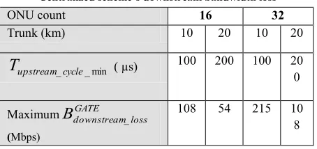
While the upstream cycle length gets shorter, the number of upstream cycles per second increases significantly. Thus, at a low network load the total number of grants/second issued by the OLT increases. The number of upstream grants per cycle is equal to the number of ONUs in the network. Therefore, increased ONU count also results in greater loss of downstream bandwidth. The maximum loss of downstream bandwidth due to the GATE message is as follows:
N
*
G
1
min _ _ _ cycle upstream GATE loss downstreamT
B
, whereG = size of GRANT (84 B * 8 = 672 bits)
GATE
loss downstream
B
_ = loss of downstream bandwidthmin _ _cycle upstream
T
= minimum upstream cycle time [image:3.612.332.559.153.260.2]N = number of ONUs
Table 1
Centralized scheme’s downstream bandwidth loss
ONU count 16 32
Trunk (km) 10 20 10 20
min _ _cycle upstream
T
( µs) 100 200 100 200
Maximum
B
downstreamGATE _loss (Mbps)108 54 215 10 8
Table 1 illustrates the worst-case downstream bandwidth loss under various conditions. At lower upstream load, where the Total Network Load (TNL) < 0.1 for 32 ONUs with a 10 km trunk, the downstream bandwidth loss could be as much as 200 Mbps (20% of total bandwidth). As the upstream load grows, the cycle length reaches the maximum (~2 ms, regardless of OLT distance from ONUs), causing the downstream bandwidth loss to be at its minimum: Mbps b T B cycle upstream GATE loss
downstream 32*672 ~11
1
max _ _
_
Under the given conditions, the GATE loss could be 11 Mbps to 215 Mbps.
B. Inefficiency due to LAN emulation
Due to LAN emulation, ONU LAN traffic is sent to the OLT to be broadcasted back to ONUs. The downstream bandwidth loss due to LAN traffic is equivalent to the amount of upstream LAN traffic. We define LAN loss as follows:
LAN
waste downstream
B
_ = P * Lupstream , whereP = percentage of upstream network load (LAN) Lupstream = total upstream network load
International Journal of Emerging Technology and Advanced Engineering
Website: www.ijetae.com (ISSN 2250-2459, Volume 2, Issue 7, July 2012)4
Outgoing Ring
E
---
O
1x2 Splitter
1490/1310 nm Downstream
Rx
1490nm
Upstream
Tx
1310nm
n:(1-n)
Incoming Ring
Upstream
Rx
1310nm
.. 1310 nm
1490 nm
1310 nm
ONU Architecture and Operation
Processing downstream traffic
Processing upstream traffic
Transmission of local upstream traffic along with regenerated upstream traffic upstream traffic
1490 / 1310 nm
Filter CWDM
A C
B
CWDM
(b)
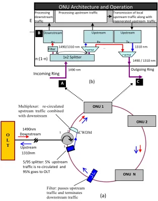
Figure 1: (a) Proposed ring-based architecture (b) ONU architecture
ONU N ONU 2
Downstream
Upstream
CWDM
1 2
3
O L T
ONU 1
Multiplexer: re-circulated upstream traffic combined with downstream
5/95 splitter: 5% upstream traffic is re-circulated and 95% goes to OLT
Filter: passes upstream traffic and terminates
downstream traffic
(a)
1310nm 1490nm
III. PROPOSED DOWNSTREAM SCHEME OVER A DISTRIBUTED RING ARCHITECTURE
The proposed downstream scheme is reliant upon a distributed architecture (distributed control plane). Therefore, it is imperative to understand how the decentralized scheme works. Fig. 1a illustrates the distributed ring-based PON architecture.
[image:4.612.128.442.144.545.2]International Journal of Emerging Technology and Advanced Engineering
Website: www.ijetae.com (ISSN 2250-2459, Volume 2, Issue 7, July 2012)5
Each ONU attaches to the ring at a (n: 1-n) 1x2 passive star coupler (incoming signal at point A in Fig. 1b) and can transmit data onto the ring through the output port of a 2x1 Coarse Wave Division Multiplexing (CWDM) combiner (outgoing signal at point C in Fig. 1b). Note that in addition to the conventional transceiver maintained at each ONU (a up upstream transmitter and a d
downstream receiver), this approach requires an extra receiver tuned at up.
Downstream signal is coupled to the ring at port 2 of the optical circulator. After recombining with the re-circulated upstream signal via another 2x1 CWDM combiner (Fig. 1a) placed on the ring directly after the optical circulator, the combined signal then circulates around the ring (ONU 1 through ONU N) in a Drop-and-Go fashion. The downstream signal is then removed at the end of the ring using a filter (located directly after the last ONU) that passes only the 1310 nm upstream signal. The upstream signal emerging from the filter at the end of the ring is split into two components via a 1x2 passive splitter (Fig. 1a) placed on the ring directly after the filter. The first component is directed towards the OLT via circulator ports 1 and 3, while the second component is allowed to re-circulate around the ring after recombining with the downstream signal (originating from the OLT) via the 2x1 CWDM combiner Fig. 1a.
The (n: 1-n) 1x2 coupler (n is a small arbitrary percentage assumed here to be 10%) splits the incoming combined signal at each node into a small (10%) ―Drop-signal-portion‖ and a large (90%) ―Go-―Drop-signal-portion‖. The small portion of the circulating combined signal dropped at each node (Drop-signal) is passed through a filter that removes the upstream signal and passes only the downstream broadcast signal, which is then received and processed by the 1490 nm downstream receiver. The remaining portion of the combined signal emerging from the 90% coupler’s port (Go-signal) is first separated into its two constituent: downstream and upstream signals via a CWDM filter. The separated upstream signal (second component) is received and processed via the 1310 nm upstream optical receiver housed at the ONU, where it is then regenerated and retransmitted along with the ONU’s own local control and data traffic.
Finally, the separated downstream signal is re-combined again with the retransmitted upstream signal (regenerated plus local) via the 2x1 CWDM of Fig. 1b to form the outgoing combined signal (incoming combined signal for next ONU) that circulates around the ring.
Since upstream transmission is based on a TDMA scheme, inter-ONU traffic (LAN data and control messages exchanged among ONUs) is transmitted along with upstream traffic destined to the OLT (MAN/WAN data) within the same pre-assigned time slot. The first component of the upstream signal destined to the OLT is received and processed by the 1310 nm upstream optical receiver (housed at the OLT), which accepts only MAN/WAN traffic, discards LAN traffic, and may discard or process (for reasons to be given below) the control messages. On the other hand, the second component of upstream signal is transmitted sequentially, bit by bit, around the ring from one node to the next where it is regenerated and retransmitted at each node.
Since the ring is a closed loop, upstream traffic will circulate indefinitely unless removed. The process of removing, regenerating and retransmitting the second component of the upstream signal at each node (ONU) is implemented as follows: first, the 1310 nm upstream optical receiver (housed at each ONU) terminates all upstream traffic, examines the destination MAC address of each detected Ethernet frame, and then performs one or more of the following functions: (1) all re-circulated upstream traffic addressed to the OLT is removed by the first ONU (ONU that is physically located on the ring directly after the 2x1 CWDM coupler of Fig. 1a); (2) all control messages (REPORTs) must be processed, regenerated, and then retransmitted by each node; (3) the source node removes its own transmitted inter-ONU control messages that complete one trip around the ring through re-circulation; (4) transient LAN traffic, terminated at an intermediate node, but destined to other nodes are regenerated and then retransmitted along with the node’s own local upstream traffic within the designated proper time slot; (5) once the destination address of the LAN traffic matches the node’s MAC address, it is copied and delivered to the end users and then discarded (not retransmitted to the next ONU).
Note that only inter-ONU control traffic completes one trip around the ring (returns to the source node); the LAN traffic is removed at the destination ONU and the MAN/WAN traffic destined to the OLT is always removed before returning to the source node except for first ONU’s traffic, which is removed by the source node (first ONU).
International Journal of Emerging Technology and Advanced Engineering
Website: www.ijetae.com (ISSN 2250-2459, Volume 2, Issue 7, July 2012)6
Additionally, the OLT is relieved from the exchanging REPORT and GATE messages for upstream bandwidth allocation; therefore, the total downstream bandwidth is available for downstream functions. Thus, this distributed scheme alleviates the centralized scheme’s downstream impediments.
In the downstream direction, the OLT houses N number of queues, each corresponding to an ONU. Incoming traffic is sorted according to destination ONU addresses and accepted into corresponding queues. Periodically, the OLT checks the downstream queue occupancy and carries out bandwidth allocation for each queue. In other words, the OLT simply divides available downstream bandwidth among the queues to allocate downstream transmission timeslots. The three variants of decentralized downstream bandwidth distribution schemes will be further discussed: the Fixed Maximum Limit (FML), Cycle Remainder Redistribution (CRR), and Max-Min Fair (MMF) schemes. A. Fixed Maximum Limit
This is a simple distribution scheme which uses the same distribution approach as used in limited IPACT [3]. Since the centralized limited IPACT scheme is simple and was shown to exhibit good performance in the upstream direction, its bandwidth distribution scheme will be our reference model for comparing the performance of decentralized schemes with that of the centralized scheme. In every cycle, the available downstream bandwidth is divided among the queues in the following manner:
max max maxB
Q
if
B
B
Q
if
Q
B
i i i Granted iwhere [R *T ]
N 1 _cycle_max downstream EPON max
B
REPON = OLT to ONU (downstream) transmission line rate
N = number of queues in OLT
Tdownstream_cycle_max =maximum cycle time
In other words, the queue is granted the requested number of bytes, but no more than a given predetermined
max
B . A queue size over Bmax will be granted bandwidth in the next cycle.
B. Cycle Remainder Redistribution
Cycle Remainder Redistribute works similarly to Fixed Maximum Limit, but eradicates the shortcomings of FML. The FML scheme suffers from a limitation due to the bursty nature of Ethernet traffic.
In an instant, some queues may have less traffic to transmit while others may require more bandwidth than Bmax. For instance, assume that Qi size is small (Qi < Bmax),
while Qj size is large (Qj > Bmax). Although there is an
excess amount of bandwidth (Bmax – Qi) that can be granted
to Qj, due to the limitation of the distribution method, the
maximum bandwidth that may be granted to Qj is only
Bmax. Note that to support CRR DBA, unlike FML, OLT
has to consider overall queue occupancy of the system (i.e. bandwidth allocation cannot be done on a one-to-one basis). Therefore, we propose the redistribution of the unused cycle remainder from the low occupancy queue to the high occupancy queue to enhance efficiency without neglecting fairness. Based on their sizes, the OLT queues can be classified into two groups, namely low occupancy queues whose sizes are smaller than Bmax and high
occupancy queues whose sizes are greater than Bmax.
During each cycle, the DBA module must keep track of the unused cycle bandwidth from the set of low occupancy queues. It must then redistribute this excess bandwidth to other high occupancy queues according to the ratio of their sizes, that is, two queue sizes Q1 and Q2 which are greater than Bmax will be assigned excess bandwidths proportional
to Q1 and Q2.
During each cycle, the low occupancy queues with Qi <
Bmax will contribute a total remainder cycle bandwidth:
) Q (B i L i max
inder Cycle_RemaB L: Number of low occupancy
queues
The high occupancy queues with Qi > Bmax will require a
total over the limit cycle bandwidth:
) B
(Q max
H
i i _OverLimit
CycleB H: Number of high
occupancy queues
The total remainder cycle bandwidth can be fairly distributed amongst the high occupancy queues to expand their maximum transmission window as follows [12]:
OverLimit Cycle inder Cycle_Rema extra iB
B
B
_ max iQ
B
where
Bi is the extra bandwidth allocated to Qi. Thegranted bandwidth, BGH, for a high occupancy queue Qi is
given by: max
B
B
B
extra i GHi
If Qi is the queue size, BGranted is the bandwidth granted
International Journal of Emerging Technology and Advanced Engineering
Website: www.ijetae.com (ISSN 2250-2459, Volume 2, Issue 7, July 2012)7
OverLimit Cycle mainder Cycle i GH i OverLimit Cycle mainder Cycle i i i i Granted i B B B Q if B B B B Q if Q B Q if Q B _ Re _ max _ Re _ max max & &C.Max–Min Fair (MMF)
Finally, we introduce a bandwidth distribution scheme named Max–Min Fair share [13, 14]. Note that when the accumulative bandwidth demand of all queues is less than the available cycle bandwidth, then each queue is allocated a share equal to its demand. The scheme is as follows: intuitively, a fair share allocates the whole amount requested to a queue that has a "small" demand, and evenly distributes unused resources to the "high-demand" queues. While sharing C bandwidth among n queues, where
C
Q
n i i
1, the order of calculation is as follows:
1) resources are allocated in order of increasing demand ( Q1 ≤ Q2 ≤ ... ≤ Qn )
2) no queue gets a resource share larger than its demand ( )
/ ,
min(Q C n
B i
Granted
i )
3) no other allocations satisfying (2) have a higher minimum allocation
4) condition (3) holds recursively as we remove the minimal user and reduce the total resource accordingly 5) queues with unsatisfied demands get equal shares of the
resources Granted
i Granted
i B
B 1 .
Note that since the OLT houses all queues and allocates bandwidth, the order of transmission is not important in our discussion.
IV. SIMULATION RESULTS
In this section, we compare the simulation performance of the proposed distributed downstream scheme with that of the centralized downstream scheme. An event-driven packet-based simulation model was developed using C++. Two simulation programs with identical network parameters were developed, one for the centralized architecture and the other for the decentralized architecture. Initially we employed the Fixed Maximum Limit (FML) distribution scheme for both the centralized and decentralized schemes to demonstrate the architectural advantage of the proposed scheme. Then we repeated the decentralized downstream simulation with enhanced DBAs (CRR, FMM) for a comparative analysis among the decentralized downstream DBAs.
The performance metrics used here are average packet queuing delay, utilization, packet loss ratio, and queue size. To compare the performance results of the proposed distributed scheme with that of the centralized scheme, we use the following system parameters: the OLT houses 32 queues corresponding to 32 ONUs, the downstream link rate is 1 Gb/s, the incoming data rate to the OLT queues is 50 Mbps, each queue size is 5 MB, the trunk length ~ 10 km, and the maximum downstream cycle time TMAX is 2
ms. Parameters specifically associated with the centralized architecture are as follows: the upstream link rate is 1 Gb/s, the inter-ONU upstream transmission guard time (Tguard) is
1 µs, the downstream GRANT message size is 84 B, and the LAN traffic is assumed to be 20% of total upstream traffic [4]. The traffic model used here is the same as that reported in [3],where each queue has a number of ON/OFF sources, each with a Pareto distribution governing the lengths of the ON/OFF periods, in order to capture the self-similar nature of Ethernet traffic [15, 16]. All frames arriving at the OLT are then queued in a first-in–first-out buffer. Each point on the following plots corresponds to a sample of 50 million packets averaged over four different runs. In the following three subsections, the simulations will be repeated for different distribution schemes. In Section A and B, the centralized scheme is compared to the decentralized scheme using a Fixed Maximum Limit distribution scheme (including LAN traffic) and in Section C a few variants of decentralized DBAs (CRR, FMM) are compared among themselves.
A. Downstream performance ( centralized vs decentralized)
International Journal of Emerging Technology and Advanced Engineering
Website: www.ijetae.com (ISSN 2250-2459, Volume 2, Issue 7, July 2012)International Journal of Emerging Technology and Advanced Engineering
Website: www.ijetae.com (ISSN 2250-2459, Volume 2, Issue 7, July 2012)9
Therefore, GATE loss is inversely proportional to the cycle length. Conversely, the LAN loss is proportional to the cycle length/TNL. The LAN traffic load increases as the TNL increases, causing more downstream bandwidth wastage. Figure 3 depicts the centralized scheme’s downstream bandwidth wastage due to GATE messages and LAN traffic as well as the accumulative wastage due to both losses. As we see in the figure, regardless of upstream network load, the minimum downstream bandwidth wastage is over 210 Mbps for the centralized architecture with LAN emulation.
Figure 4 shows the average frame queuing delay for centralized and decentralized schemes. The centralized delay is always longer than the decentralized one. At a low downstream TNL, the effective downstream bandwidth in the centralized scheme is at least 20% less than in the decentralized scheme. Note that it is still adequate to serve the queues at low load. But the OLT’s additional GATE and LAN function in the centralized scheme causes the downstream cycle to become longer than in the decentralized scheme. The consequence is a comparatively longer buffer stay, resulting in a longer queuing delay in the centralized network even though the bandwidth is adequate. On the other hand, at a higher TNL, the centralized scheme suffers from lack of available bandwidth; therefore, it cannot serve as much traffic in a given cycle as the decentralized scheme does. Packets have to wait in queues for the next cycle, causing more queuing delay. This longer queue occupancy results in comparatively larger queue sizes for the centralized scheme than for the decentralized scheme (see Fig. 5). At higher loads the queue sizes become larger and at TNL ~ 1, queues are saturated, causing packet drop. Figure 6 depicts this fact; since the centralized scheme has a comparatively larger queue size, it causes more packet drop than the decentralized scheme.
Note that the utilization is similar in both cases until the TNL ~ .75 (Fig. 7). Due to the low TNL, most of the cycle is unused for both cases. The centralized architecture uses that time for GATE and LAN messages, whereas the decentralized scheme just waits without doing anything. The average usage of bandwidth is similar, until the demand gets higher and the centralized scheme cannot serve as much as the decentralized scheme does due to the reduction in available downstream bandwidth (over 20%).
This reduction in bandwidth confines the centralized utilization to below 80% at high TNL.
B. LAN traffic performance( centralized vs decentralized) In this section, we observe the LAN traffic performance between the centralized and decentralized scheme. Note that for the centralized scheme, the LAN traffic is the upstream traffic redirected as downstream traffic by OLT through LAN emulation. Fig. 8 compares the average end-to-end packet delay of LAN traffic as a function of TNL (upstream), for both centralized IPACT [3] and decentralized scheme. As can be seen from the figure, at all network loads, the average end-to-end packet delays of the distributed scheme are always less than those of the centralized one. At low load, centralized scheme has about 250-350 µs longer average end-to-end delays than that of the decentralized one. This is mainly due to the round-trip-time (RTT) delay from the ONUs to the OLT, beside the queuing delay. In the case of the proposed distributed ring-based architecture, the maximum delay between the two most distant ONUs on the ring is about 15µs. At higher load, as queuing delay becomes higher and dominant, the delays get higher and difference between the two schemes are now in milliseconds.
C. Downstream performance ( various decentralized schemes)
International Journal of Emerging Technology and Advanced Engineering
Website: www.ijetae.com (ISSN 2250-2459, Volume 2, Issue 7, July 2012)International Journal of Emerging Technology and Advanced Engineering
Website: www.ijetae.com (ISSN 2250-2459, Volume 2, Issue 7, July 2012)11
REFERENCES
[1 ] S. De, V. Singh, H. M. Gupta, N. Saxena, and A. Roy, ―A new predictive dynamic priority scheduling in Ethernet passive optical networks (EPONs),‖ Optical Switching and Networking, vol. 7, no. 4, pp. 215–223, 2010.
[2 ] IEEE 802.3ah EFM Study Group,
http://www.ieee802.org/3/efm/public/index.html.
[3 ] G. Kramer et al., ―Interleaved polling with adaptive cycle time (IPACT): A dynamic bandwidth distribution scheme in an optical access network,‖ Photonic Network Comm, vol. 4, no. 1 pp. 89–107, Jan. 2002.
[4 ] A. Hossain, R. Dorsinville, M. Ali, A. Shami, and C. Assi, "Ring-based local access PON architecture for supporting private networking capability," J. Opt. Network. Vol. 5, pp. 26-39, 2006.
[5 ] C.-J. Chae et al., ―A PON system suitable for internetworking optical network units using a fiber Bragg grating on the feeder fiber,‖ IEEE Photon. Technol. Lett., vol. 11, pp. 1686–1688, Dec. 1999.
[6 ] E. Wong et al., ―CSMA/CD-based EPON with optical internetworking capability among users,‖ IEEE PTL, vol. 16, no. 9, pp. 2195–2197, Sep. 2004.
[7 ] N. Nadarajah, M. Attygalle, E. Wong, and A. Nirmalathas, ―Novel schemes for local area network emulation in passive optical networks with RF subcarrier multiplexed customer traffic,‖ J. Lightwave. Technol., vol. 23, no. 10, pp. 2974–2983, Oct. 2000.
[8 ] Chiaroni, D, et. al., ―Downstream traffic control policy of EPON based on LLID‖ Proc. SPIE Vol. 6783, November 2007.
[9 ] Jia, W. ―Performance Evaluation of Ethernet Frame Burst Mode in EPON Downstream Link‖, ETRI Journal, Volume 30, Number 2, April 2008
[10 ] ASM Delowar Hossain, et. al, "Downstream Bandwidth Allocation Scheme in Local Access over a Distributed Control Plane", in Proceedings of IEEE ICCIT 2011, Jordan, March 29-31, 2011.
[11 ] C. W. Chow and C. H. Yeh, "40-Gb/s downstream DPSK and 40-Gb/s upstream OOK signal remodulation PON using reduced modulation index," Opt. Express 18, 26046-26051 (2010)
[12 ] C. Assi et al., ―Dynamic bandwidth allocation for quality of service over Ethernet PONs,‖ IEEE J. Select. Areas Commun., Dec. 2003.
[13 ] Y. Hou, H. Tzeng, and S. Panwar, ―A generalized max–min rate allocation policy and its distributed implementation using the ABR flow control mechanism,‖ IEEE INFOCOM ’98, pp. 1366–1375, Apr. 1998. [14 ] M. Hosaagrahara and H. Sethu, ―Max–min fairness in input queued
switches,‖ ACM SIGCOMM Student Poster Session, August 2005, Philadelphia, PA, USA.
[15 ] V. Paxson and S. Floyd, ―Wide area traffic: the failure of Poisson modeling,‖ IEEE/ACM Trans. Networking, vol. 3, pp. 226–244, June 1999.