65:4 (2013) 47–51 | www.jurnalteknologi.utm.my | eISSN 2180–3722 |
Full paper
Jurnal
Teknologi
Comparative Study on Effect of PEG and PVP as Additives on Polysulfone
(PSF) Membrane Structure and Performance
Nurul Nabilah Aminudina*, Hatijah Basria, Zawati Harunb,c, Muhamad Zaini Yunosc, Goh Pei Seand
aFaculty of Science, Technology and Human Development, Universiti Tun Hussein Onn Malaysia, Batu Pahat,86400, Johor, Malaysia
bAdvanced Materials and Manufacturing Centre (AMMC), Faculty of Mechanical and Manufacturing Engineering, Universiti Tun Hussein Onn
Malaysia, Batu Pahat, 86400, Johor, Malaysia
cFaculty of Mechanical and Manufacturing Engineering, Universiti Tun Hussein Onn Malaysia, Batu Pahat, 86400, Johor, Malaysia dAdvanced Membrane Technology Research Centre (AMTEC), Universiti Teknologi Malaysia, 81310 UTM Johor Bahru, Johor, Malaysia
*Corresponding author: [email protected]
Article history
Received :21 August 2013 Received in revised form : 30 October 2013
Accepted :15 November 2013
Graphical abstract
Abstract
PSf flat sheet membrane was prepared via phase inversion technique with N-methyl-2-pyrroidone (NMP) as solvent. In this study polyethylene glycol (PEG) and polyvinylpyrollidone (PVP) were compared as additives at different composition (0.5 wt%, 1 wt%, 3 wt% and 5 wt%). The structure and morphology of the resulting membranes were observed by scanning electron microscope (SEM) and the membranes permeation were evaluated in terms of pure water flux (PWF) and solute rejection. Solution of bovine serum albumin (BSA) was used to study the performance of prepared membrane. The addition of the additives into the casting solution changed the structure of the resultant membranes, which was believed to be associated with the change the permeated of water. The results demonstrated that at the same additive content, PSf/PVP membranes had higher PWF at 0.5 wt% and and 5 wt% of additive while PSf/PEG at 1 wt% and 3 wt% of additive. The BSA rejection show no significant changes for PSf/PEG while PSf/PVP, BSA rejection decrease with increase the increasing the PVP. For PEG, additive from 0% to 5%, the PWF increased from 14.73 at to 101.85 LMH. While for PVP, the PWF increased from 21.13 to 177.61 LMH. The membrane morphology showed that all images showed the membranes were having asymmetric structure consisting of a dense top layer, a porous sublayer, and a small portion of sponge-like bottom layer. The top layer of the membrane consist of finger-like structure while at bottom layer has macrovoid structure. With increasing the additive, the finger-like structure become longer to the bottom and macrovoid become smaller. The study found that PEG gives the optimum performance based on the result of rejection and flux permeation.
Keywords: Polysulfone, polyethylene glycol (PEG); polyvinylpyrollidone (PVP); bovine serum albumin (BSA)
© 2013 Penerbit UTM Press. All rights reserved.
1.0 INTRODUCTION
In the recent years, use of membrane in various applications such as water treatment, desalination, food processing, biotechnology and many other separations is increased and become as the important process among all. A membrane must exhibit at least the following characteristics : high flux, high selectivity (rejection), mechanical stability, tolerance to all feed stream components (fouling resistance), tolerance to temperature variations, and low manufacturing cost.1 In many
cases, membrane processes are faster, more efficient and economical than conventional separation techniques. Membrane separations process can be classified as microfiltration (MF), ultrafiltration (UF), nanofiltration (NF), and reverse osmosis (RO). Membranes are generally categorized by pore size, structure and separation mechanism. There are various polymers in preparing the commercial membranes such as polysulfone (PSf), polyethersulfone (PES), polypropylene (PP), cellulose
acetate (CA), polyacrylonitrile (PAN) polyvinylidene fluoride (PVDF) and polyethylene (PE).2
In this experiment PSf is chosen as a polymeric material due to its low cost, superior film ability, good mechanical and anti-compaction properties and strong chemical and thermal stabilities. However due it hydrophobic nature, PSf membranes is susceptible to cause membrane fouling by the adsoption of proteins and other biomolecules in the feed stream. 3 When
fouling occurs in separation process, the performance of the membrane may affect in terms of flux permeation, water permeability and rejection.4To overcome the fouling problem
on PSf membrane, it is believed that the addition of additive in the membrane solution may somehow prevent the fouling from occuring. The common used additives in membrane formation such as polyethylene glycol (PEG), polyvinylpyrollidone (PVP), lithium chloride (LiCl), silver nitrate (AgNO3), titanium dioxide
(TiO2) and others.5-9 The addition of additives in membrane
hydrophilicity or hydrophobicity, increase antibacterial properties and enhance the membrane performance. 5, 10-11
Previous study stated that PEG can improve the membrane hydrophilic nature and pore distribution.12 Study of Yeo et al.,13
that used PVP in the casting solution produced membrane with enlarge macrovoid structure rather than the suppression of the structure.
The porosity and flux can be enhanced for the addition of high molecular weight (Mw) additives such as PEG and PVP. 14-15 The variation of the type and concentration of polymer,
solvents and additives were produced different viscosity of the membrane solution. Due the high number of Mw of additive,
membrane solution tends to be more viscous. The changes of the solution viscosity were change the phase separation rate which high Mw additive is less soluble than low Mw.
In this work, N-methyl-2-pyrrolidone (NMP) were used as a solvent to prepare PSf membrane. Two different types of high Mw additive, PEG 35,000 Da and PVP 360,000 Da were used as
an additive separately. The effects of additives molecular weight Mw on permeation characteristics and morphology of the
prepared membrane were investigated. Membrane performance was analyzed in terms of water permeation and protein rejection behavior. The membranes morphology were analyzed using scanning electron microscopy (SEM).
2.0 EXPERIMENTAL
2.1 Membrane Preparation
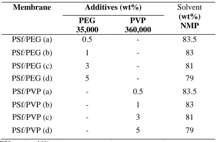
[image:2.612.64.278.458.599.2]Flat sheet PSf membranes were prepared via phase inversion method using different molecular weight of additives (PEG 35,000 Da or PVP 360,000 Da) and NMP as solvent. The PSf concentration was kept constant at 16 wt% for all cases. Table 1 shows the composition of all the membrane prepared in the study.
Table 1 Composition of the casting solution
Membrane Additives (wt%) Solvent (wt%) NMP PEG 35,000 PVP 360,000
PSf/PEG (a) 0.5 - 83.5
PSf/PEG (b) 1 - 83
PSf/PEG (c) 3 - 81
PSf/PEG (d) 5 - 79
PSf/PVP (a) - 0.5 83.5
PSf/PVP (b) - 1 83
PSf/PVP (c) - 3 81
PSf/PVP (d) - 5 79
PSf constant 16%
For dope preparation, the solution was stirred with the aid of magnetic stirrer for more than 4 h at temperature 60 oC. The
solution was further agitated for another 24 h in order to form a homogeneous solution. The solution was then cast on a clean glass plate with a casting knife maintaining at 0.1 ± 0.02 mm at
room temperature. The glass plate was then immediately immersed in the water bath and the cast films immediately changed to white colour. Finally, the washed composites were air-dried at room temperature for 1 day.
2.2 Membrane Characterization
2.2.1 Pure Water Flux and Rejection Test
The membrane was cut into desired shape and fitted in flat sheet membrane separation unit. The distilled water was fed into the flat sheet membrane separation unit from the pressure reservoir and the initial water flux was taken after flux become constant. The PWF was calculated using the equation:
(1)
where Jw is the water flux (LMH). Δt is the sampling time (h)
and A is the membrane area (m2). The solute rejection
membranes were evaluated using BSA as solute. The absorbance was measured by using the spectrophotometer (Shimadzu UV-160) at wavelength of 280 nm against a reagent blank. The solute rejection (%R) is defined as
(2) where Cp and Cf are the BSA concentration in the permeate and
in the feed, respectively.
2.2.2 Morphological Studies
The cross sectional morphology of the membranes was studied using scanning electron microscopy (SEM) model JEOL JSM-6380LA. All the samples were immersed into liquid nitrogen, fractured and then coated with platinum sputtered on sample holders to provide electrical conductivity to the very thin layers of polymeric membranes.
3.0 RESULTS AND DISCUSSION
3.1 Effect of PEG and PVP Additives on Membrane Permeability
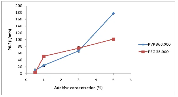
The effect of PEG and PVP additives on the PWF performance is illustrated in Figure 1. From the figure, the PWF for both PEG and PVP is increasing with the increment the additive content. Based on the experimental results, the PWF of PSf/PEG was increased from 14.73 at 0.5 wt% PEG to 101.85 LMHat 5 wt% composition of PEG. On the other hand, the PWF of PSf/PVP was increased from 21.13 at 0.5 wt% PVP to 177.61 LMH at 5 wt% composition of PVP. The addition of PEG and PVP to the casting solution increased the water permeation. In the casting solution, PEG was used as pore forming agent to improve the permeability of membrane.12,16 While, the addition
of PVP to the casting solution will effect on the pore formation mechanism and thus directly influence the membrane porosity.17
Figure 1 Effect of additives concentration (%) on the PWF
3.2 Effect of PEG and PVP Additives on BSA Rejection
Figure 2 illustrates the effect of different loading of additives to BSA rejection performance (%R). Based on the plot, PEG shows no significant changes in term of BSA rejection compared to PVP. The PSf/PEG shows no obvious changes in BSA rejection when PEG content is increased. Similar results were obtained by Yuxin Ma et al,.6 The PSf/PVP at 0.5 wt% of
additive recorded the highest BSA rejection at 92.21% rejection and reduced to 27.41% at 5 wt% of PVP. The BSA rejection is
decreased with increasing the additive composition due to the pore size of skin layer becomes larger. The presence of PVP in the casting solution has contributed to the enlargement of microvoid in membrane structure.13 Chakrabarty et al.,7 had
stated that membrane prepared with PVP can be considered better than those prepared with PEG in term of BSA rejection. However in this study the situation is vice versa. High molecular weight of additive can be trapped in the membrane because of their lower mobility after immersion in the coagulation bath wich results in the formation of larger pores in the skin layer.6
Figure 2 Effect of additives concentration (%) on the BSA rejection
3.2.1 Morphological Study
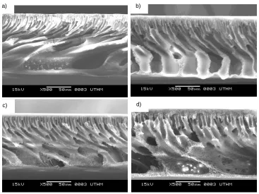
The cross sectional morphologies of PSf membrane prepared using PEG and PVP as additive for various concentrations were shown in Figure 3 and 4, respectively. All images showed the membranes were having asymmetric structure consisting of a dense top layer, a porous sublayer, and a small portion of sponge-like bottom layer. The skin layer acts as a separation layer and the support layer provides the mechanical strength. The sub layer seems to have finger like cavities beneath the top surface layer as well as macrovoids structure. The observations were similar by Chakrabarty et al. where PSf was used as a polymer, NMP and DMAC as solvent, and PEG and PVP as an additive. 7,12 The formation of finger-like structure in the
sublayer is attributed to the instantaneous demixing which is due to high mutual affinity of solvent and coagulant.2,18
Figure 3 shows the variation in the morphologies of the membrane with different concentration of PEG. The image captured show that by adding PEG as additive the formed finger-like structures at top layer of the membrane and pore becomes bigger in size and longer to the bottom of the membrane. The same effect on membrane morphology was observed for Figure 4. It is clear from these images that the finger-like structures are suppressed by the addition of PEG and PVP. However, the differences between membranes (PSf/NMP/PVP) in Figure 4 were significant at top layer. In Figure 4 (d), the top layer is thicker compared to other membranes and more porous. This is due to the molecular weight (Mw) of PVP that is higher than Mw of PEG. The higher
the Mw of additive makes the membrane solution concentrated
[image:3.612.160.455.377.523.2]kinetic hindrance to phase separation, resulting in the suppression of macrovoid formation in the membranes. Besides that, a high Mw additive is less soluble than low Mw. Low Mw
additives can be washed out together with the solvent from the membrane film in the coagulation bath. Therefore, the higher molecular weight take more time to reach the surface and this
will give a sufficient time for polymer aggregates on the top layer to form a thicker layer.20
In fact, by increasing the additive (PEG/PVP) content, the finger-like structure become longer and irregular sponge macrovoids become less in sizes at the bottom layer. This straight or long finger-like structure formed at the bottom give better permeation compared to short finger-like structure. 21
[image:4.612.124.483.144.410.2]
Figure 3 Cross section SEM image of PSf/PEG at different PEG concentration (a) 0.5 wt%, (b) 1 wt%, (c) 3 wt% and (d) 5 wt%
Figure 4 Cross section SEM image of PSf/PVP at different PVP concentration (a) 0.5 wt%, (b) 1 wt%, (c) 3 wt% and (d) 5 wt% a)
c)
b)
d)
a
)
c)
b
)
d
)
a)c)
b)
[image:4.612.118.485.442.717.2]4.0 CONCLUSION
In this study, flat sheet PSf membrane were successfully prepared using phase inversion process containing 0.5, 1, 3 and 5 wt% Peg and PVP as additives with NMP as a solvent. By increasing the percentage of PEG and PVP additives, membrane permeability seem to increase and in reverse decreased the rejection of BSA solution. However, no significant changes of BSA rejection was observed for PSf/PEG. For both PEG and PVP at 5 wt%, the highest PWF were recorded. Another interesting finding is PSf/PEG can reject BSA solution effectively compared to PSf/PVP. As a conclusion, PEG 35,000 Da gives the best possible performance based on the result of rejection and flux permeation.
Acknowledgement
Financial support from the Ministry of Higer Education with Research Grants Scheme vot A022 is acknowledged with gratitude.
References
[1] I. Pinnau and B. D. Freeman. 1999. Formation and Modification of
Polymeric Membranes: Overview. ACS Symposium Series; American Chemical Society.
[2] M. Mulder. 1991. Basic Principles of Membrane Technology. Kluwer
Academic Publishers.
[3] Haijun Yua, Yiming Caoa, Guodong Kanga, Jianhui Liua, Meng Li ,
Quan Yuana. 2009.J. Membr. Sci. 342: 6–13.
[4] L. Yan, Y. Li, C. Xiang, and S. Xianda. 2006. J. Membr. Sci. 276(1–2):
162–167
[5] H. Basri, A. F. Ismail, M. Aziz. 2011. Desalination. 273: 72–80.
[6] Yuxin Ma, Fengmei Shi, Jun Ma, Miaonan Wu, Jun Zhang and Congjie
Gao. 2011.Desalination. 272: 51–58.
[7] B. Chakrabarty, A. K. Ghoshal and M. K. Purkait. 2008. J. Membr. Sci.
315: 36–47.
[8] M. Tomaszewska. 1996. Polymer. 40: 6499–6506.
[9] N. A. A. Hamid, A. F. Ismail, T. Matsuura, A. W. Zularisam, W. J.
Lau, E. Yuliwati, M. S. Abdullah. 2011. Desalination. 273: 85–92.
[10] A. Mansourizadeh, A. F. Ismail, 2010. J. Membr. Sci. 348: 260–267.
[11] A. Idris, Mat Zain, N., and M. Y. Noordin. 2001. Desalination. 207:
324–339
[12] B. Chakrabarty, A. K. Ghoshal and M. K. Purkait. 2008.J. Membr. Sci.
309: 209–221.
[13] H. T. Yeo, S. T. Lee and M. J. Han. 2000. J. Chem. Eng. Jpn. 33:180–
185.
[14] Y. Zhou, D. L. Xi. 2008. Desalination. 223: 438–447.
[15] H. A. Tsai, L. C. Ma, F. Yuan, K. R. Lee, J. Y. Lai. 2008.
Desalination. 234: 232–243.
[16] G. Arthanareeswaran, D. Mohan, and M. Raajenthiren. 2007. App.
Surf. Sci. 253: 8705–8712.
[17] S. A. Al Malek, M. N. Abu Seman, D. Johnson and N. Hilal. 2012.
Desalination. 288: 31–39.
[18] P. Y. Qin, C. X. Chen, B. B. Han, S. Takuji, J. D. Li, B. H. Sun. 2006.
J. Membr. Sci. 268: 181–188
[19] S. H. Yoo, J. H. Kim, J. Y. Jho, J. Won, and Y. S. Kang. 2004. J.
Membr. Sci. 236: 203–207
[20] J. K. Y. B. Jung, B. Kim, H.W. Rhee. 2004. J. Membr. Sci. 243: 45–57
[21] M. Z. Yunos, Z. Harun, H. Basri and A. F. Ismail. 2012. Advanced