Traffic Light Security Alarm Control System Using
Pic Microcontroller
Yan Naung Soe*, Khet Khet Khaing Oo**
*Faculty of Information Technology Support and Maintenance, University of Computer Studies, Myitkyina **Faculty of Computer Systems and Technologies, University of Computer Studies, Monywa
DOI: 10.29322/IJSRP.9.07.2019.p91125
http://dx.doi.org/10.29322/IJSRP.9.07.2019.p91125
Abstract- The more developing the country, the higher the living standard of the people, and the denser the traffic will be. So, there are a lot of traffic congestions and the monitoring and control of city traffic is becoming a major in many countries. The idea of intelligent traffic system is that drivers will not spend time waiting for the traffic light to change.
PIC controlling system is widely used and very popular around the world. Microcontroller control system with traffic security alarm is proposed in this paper. The proposed system is a combination of hardware and software devices. And this is the real time control system with fast dynamics situation. This is implemented by using assembly language programming.
Index Terms- Programmable Interface Controller (PIC),embedded system, security control system, detected circuit, PIC 16F877A single display, Power Electronic Devices,
I. INTRODUCTION
his system utilizes the traffic light security alarm to control the traffic light. There are one main road and one side street at a certain traffic junction. This system aims to develop a computer implemented PIC controller system that would automatically generate the durations of the green light to be lit for both ways as control output giving the main road higher priority. The traffic light is to have three lights (red, yellow, green), be able to shine red, yellow, and green for a certain number of seconds each, and be able to repeat this sequence indefinitely.
It is of a computer that controls the selection and timing of traffic movements in accordance to the varying demands of traffic signal as registered to the controller unit by sensor. The second part is that the visualization is signal face. Signal faces are part of a signal head provided for controlling traffic in a signal direction and consist of one or more signal sections.
These usually comprise of solid red, yellow and green
logic, MATLAB software, Lab VIEW software, PIC microcontroller is used in developing this traffic light control system. Owing to using the chip of PIC microcontroller with sensor, this system developed more than other.
The sensor will help to alarm in crossing the road at the wrong signal. In this system, microcontroller is applied of secure system. Nowadays, PIC microcontroller is used for a few kilobytes requirements of device control instead for a few kilobytes requirements of device control instead of personal computer. PIC microcontroller is very useful in the application areas of communication, transportation, product manufacturing and automatic control etc [2] [3]. Microcontrollers have traditionally been programmed using the assembly language of the target device. Although the assembly language is fast, it has several disadvantages. An assembly program consists of mnemonics and it is difficult to learn and maintain a program written using the assembly language.
High level language has the advantage that it is much easier to learn a high level language than the assembly. Also, very large and complex program can easily be developed by using a high level language.
III. MICROCONTROLLER
Circumstances that we find ourselves today in the field of microcontrollers had their beginnings in the development of technology of integrated circuits. This development had made it possible to store hundreds of thousands of transistors into one chip. That was a prerequisite for production of microcontrollers, and adding external peripherals such as memory, input- output lines, timers and other made the first computers. Further increasing of the volume of the package resulted in creation of integrated circuits.
These integrated circuits contained both processor and peripherals. That is how the first chip containing a microcomputer,
application because all necessary peripherals are already built in to it. Thus, we save the time and space needed to construct devices [5] [7].
General features of PIC 16F877A
General features of PIC16F877A are RISC (Reduced instruction Set Computer). The PIC 16F877A microcontroller is the midrange microcontroller from the Microchip technology Inc [1]. It has the following features:
- 40 pins devices (33 input / output pins) - 8192*14 flash program memory - 368 bytes of RAM
- 256 bytes of EEPROM
- 8 multiplexed A/D converters with 10 bits resolution - 3 timers, analogue capture and comparator circuit, USART and internal and external interrupt facilities - 10000 erase/write cycles
- 1 K word of program - timer and interrupt functions
IV. HARDWARE COMPONENTS
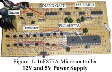
[image:2.612.338.554.56.201.2]This system includes three major hardware components: the controller implemented to the system, the LDR sensors which detect the presence of vehicles, the light emitting diodes (LED) which act as the actuator and the countdown timers [6] ,12V and 5V power supply and the 555 timer used as a timer in alarm generating circuit is also discussed.
Figure 1. 16F877A Microcontroller 12V and 5V Power Supply
A power supply is an essential part of each electronic system from the simplest to the most complex. The DC power supply converts the standard 220v, 50Hz AC into a constant DC voltage. The DC voltage produced from a power supply is used to power all types of electronic circuits. In this system, full wave bridge rectifier uses four diodes. Diodes are used in circuits as rectifiers that convert AC voltage to DC voltage as shown in Figure 2.
C1…22µF 50V C2,C4…10 µF50V
R1…,R2….1KΩ C3,C5…0.1µF
Figure 2. 12V and 5V Power Supply Circuit
555 Timer-monostable and astable
The 8-pin 555 timer is one of the most useful chips ever made and it is used in many projects. With just a few external components it can be used to build many circuits, not all of them involve timing. So, it is a versatile and widely used device. It can be configured in two different modes as either a monostable multivibrator (one-shot) or as an astable multivibrator (oscillator), an astable multivibrator has no stable states and therefore changes back and forth (oscillates) between two unstable states without any external triggering. There are several reliable timers but the 555 timer is the most common whether you are putting together an alarm or a circuit to activate a computer a timer is the common component [4].
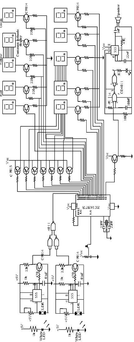
[image:2.612.72.266.398.522.2]Figure 3. Circuit Diagram of Security Alarm Control System Using PIC16F877A
light signal operation will start with the traffic light illuminating in red for 25 seconds in all directions. It will start operating in the North lane [6], the East lane, South lane, the West lane and then goes back to the North lane. Firstly, simulator will check the north lane condition. It will check whether the sensors are triggered or not.
The total number of the sensors triggered will be used in the mathematical function to calculate the appropriate timing for the green signal to illuminate. After the green signal finishes the illumination of timing, the yellow signal will illuminate for 3 seconds, and finally the red signal will illuminate [6]. The yellow signal means that vehicles and passers-by are standby.
[image:4.612.352.536.58.429.2]The red signal means to wait for the countdown and the green, to cross the road safely. Of course, if a vehicle or man on the road at the red signal crosses the road, and then sensor device will receive the object and alarm control will broadcast. This system will save the waiting time of vehicles to cross the road. Since the waiting time of the vehicles for the true signal is optimal, the emission of carbon monoxide from the vehicles can be reduced. This will also save a positive effect to the green house effect towards the environment [6]. This system will save the motorists’ time .It will help reducing the traffic congestion. Moreover, in crossing the road at the wrong signal, alarm control will help to broadcast. So, any vehicle and passer-by can cross the road safely and sound at the green signal.
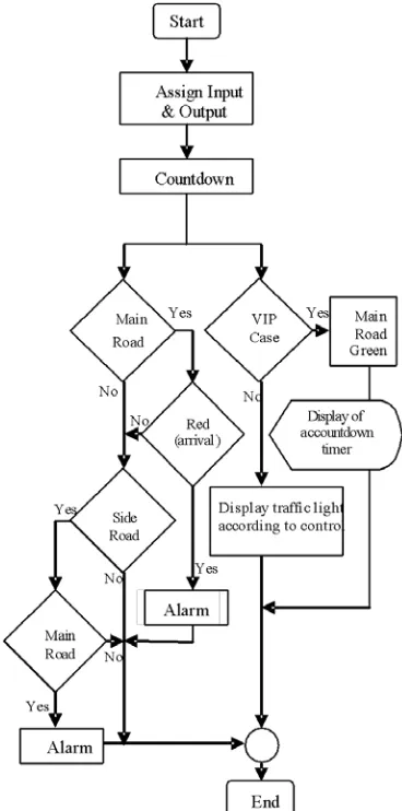
Figure 5. Flow Diagram of Proposed System
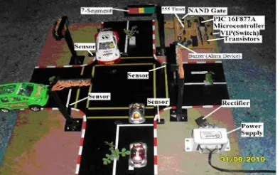
[image:4.612.341.549.469.591.2]Figure 7. Model of the traffic light security alarm control system
VII. CONCLUSION
This traffic light control system develops more than normal one. For, the system had successfully been designed under the control of the sensor. The sensors are interfaced with Lab VIEW integrate system [6]. This interface is synchronized with the whole process of the traffic system. It is this prototype (figure 7) in the real life situation.
The sensors will detect the presence or absence of vehicles or passers-by [6]. Crossing the road at the wrong signal which is that there is a vehicle or passer-by on the road at the red signal,
alarm control will help to broadcast. And, the system consists of the sensors to detect in all directions so that it has a wide range of detection capabilities, which can be enhanced and ventured into a perfect traffic system [6].
REFERENCES
[1] https://microcontrollerslab.com/pic16f877a-introduction-features/ [2] https://www.edgefx.in/pic-microcontroller-architecture-and-applications/
[3] Solomon, S., 1999. Sensors Handbook. McGrawHill, New York.
[4] Nise, N.S., 1995. Control Systems and Engineering. Addison Wesley. 2nd
Edition.
[5] http://www.microchip.com
https://www.researchgate.net/publication/26439807_Design_ad_Developm ent_of_Sensor_Based_Traffic_Light_System
[6] https://www.authorstream.com/Presentation/dineshshankar3 53-2020457-pci-microcontroller/
AUTHORS
First Author – Yan Naung Soe, Faculty of Information Technology Support and Maintenance, University of Computer Studies, Myitkyina