COMPUTATIONAL STUDY ON SHEAR STRENGTHENING OF RC CONTINUOUS BEAMS USING CFRP SHEET
NABIL MOHAMED EMHDAB ALNATIT
A thesis is submitted of the fulfillment of the requirements
for the award of the degree of Master of Civil
Engineering
Faculty of Civil and Environmental Engineering
University Tun Hussein Onn Malaysia (UTHM)
ABSTRACT
This research studied the feasibility and effectiveness of a new method of strengthening
existing RC continuous beams in shear by using CFRP strips. The CFRP composite strips were used to strengthen concrete externally at a known failure plane to resist shear stresses in shear friction. All beams were design to fails in shear with av/d 2.5. This research describes the computational study on shear strengthening of RC continuous beams using CFRP strips. In this study, a computational program consisting of 5 beams were performed subjected to experimental program with the same size and details of the beams where the experimental study was performed by other student in the laboratory. Here in this part the study done through simulation by ABAQUS Software version 6.9. Therefore, this research aims to investigate the effectiveness of using externally bonded CFRP strips in repair and strengthen of RC continuous beams and also to know the behavior of RC continuous beams strengthened in shear with CFRP sheet. So in this study there are five specimens with different CFRP wrapping scheme as 90 degree and
45 degree with three sides and four sides each beam. The computational results were
ABSTRAK
Kajian ini dijalankan bagi mengkaji keberkesanan kaedah baru bagi pengukuhan ricih
CONTENTS
TITLE I
DEDICATION II
ACKNOWLEDGEMENT III
ABSTRACT IV
ABSTRAK V
CONTENTS VI
LIST OF TABLES XI
LIST OF FIGURES XII
CHAPTER 1 INTRODUCTION
1.1 Introduction 1
1.2 Problem Statement 2
1.3 Objectives of Project 2
1.4 Scope of Project 3
CHAPTER 2 LITERATURE REVIEW
2.1 Introduction of FRP 4
2.2 Fiber reinforced polymer 5
2.2.1 History of FRP 5
2.2.2 Definition of FRP 7
2.2.3 Types of CFRP 8
2.2.4 The uses of FRP 9
2.2.5 Advantages of FRP 10
2.2.6 Disadvantages of FRP 12
2.3 Shares strength of reinforced concrete using FRP 12
2.3.1 The equation used to calculate shear strength 13
2.3.1.1 ACI Code provisions for shear strength of Beams 13
2.3.1.2 Khalifa Equation 14
2.4 Finite element analysis 16
6.2 Conclusion 17
CHAPTER 3 RESEARCH METHODOLOGY 3.1 Introduction 18
3.2 Beam details 18
3.3 Materials of the beams 21
3.4 Abaqus software 22
3.4.1 Introduction to Abaqus/CAE 22
3.4.3.1 Components of the main window 24
3.4.4 Systems support 25
3.4.5 Exiting an ABAQUS/CAE session 25
3.4.6 ABAQUS Finite Element System 25
3.4.7 Finite Element Meshes 26
3.4.8 Material modeling 29
3.4.9 Boundary condition 29
3.4.10
Analysis Running and Results 30
CHAPTER 4 RESULTS AND DISCUSSION
4.1 Introduction 32
4.2 Ultimate load 32
4.3 Load Displacement Behavior 33
4.3.1 Comparison between simulation and experimental study 34
4.3.1.1 Comparison between simulation and experimental for C2.5-C 34
4.3.1.2 Comparison between simulation and experimental for C2.5- UA-S 35
4.3.1.3 Comparison between simulation and experimental for C2.5-U-S 36
4.3.1.4 Comparison between simulation and experimental for C2.5-LA-S 37
4.3.1.5 Comparison between simulation and experimental for C2.5-L-S 38
4.4 Load - Main Reinforcement Strain 39
4.4.1 Comparison between simulation and experimental for C2.5-C 40
4.4.2 Comparison between simulation and experimental for C2.5-UA-S 41
4.4.4 Comparison between simulation and experimental for C2.5-LA-S 43
4.4.5 Comparison between simulation and experimental for C2.5-L-S 44
4.5 Load – strain results 45
4.5.1 Load – stirrups strain 45
4.5.1.1
Load-Stirrups Strain Behavior of C2.5-C, (S1, S2, S3, and S4) 45
4.5.1.2 Load-Stirrups Strain Behavior of C2.5-UA-S, (S1, S2, S3, and S4) 47
4.5.1.3 Load-Stirrups Strain Behavior of C2.5-U-S, (S1, S2, S3, and S4) 49
4.5.1.4 Load-Stirrups Strain Behavior of C2.5-LA-S, (S1, S2, S3 and S4) 51
4.5.1.5 Load-Stirrups Strain Behavior of C2.5-L-S, (S1, S2, S3, and S4) 53
4.5.2 Load - concrete surface strain 55
4.5.2.1 Load-Concrete Surface Behavior of C2.5-C for (C1, C2, C3 and C4) 56
4.5.2.2 Load-Concrete Surface Behavior of C2.5-UA-S for (C1, C2, C3 and C2) 58
4.5.2.3 Load-Concrete Surface Behavior of C2.5-U-S for (C1, C2, C3 and C4) 60
4.5.2.4 Load-Concrete Surface Behavior of C2.5-LA-S for (C1, C2, C3 and C4) 62
4.5.2.5 Load-Concrete Surface Behavior of C2.5-L-S for (C1, C2, C3 and C4) 64
4.5.3 Load – CFRP strain 66
4.5.3.1 Load CFRP Behavior of C2.5-UA-S for (F1, F2, F3 and F4) 66
4.5.3.2 Load CFRP Behavior of C2.5-U-S for (F1, F2, F3 and F4) 68
4.5.3.3 Load CFRP Behavior of C2.5-LA-S for (F1, F2, F3, and F4) 70
CHAPTER 5 CONCLUSIONS AND RECOMMENDATIONS
5.1 Introduction 74
5.2 Conclusion 74
5.3 Recommendation 75
REFERENCE 76
LIST OF TABLES
Table 3.1:
Information of all beams 19
Table 3.2:
Properties of Sikadur-330 (Sika kimia, 2009) 21
Table 4.1:
The ultimate load for all specimen 32
Table 4.2:
The displacement for C2.5-C 34
Table 4.3:
The displacement for C2.5-UA-S 35
Table 4.4:
The displacement for C2.5-U-S 36
Table 4.5:
The displacement for C2.5-LA-S 37
Table 4.6:
The displacement for C2.5-L-S 38
Table 4.6:
The Reinforcement for C2.5-C 40
Table 4.7:
Load – Main Reinforcement Strain for C2.5-UA-S 41
Table 4.8:
Load – Main Reinforcement Strain for C2.5-U-S 42
Table 4.9:
Load – Main Reinforcement Strain for C2.5-LA-S 43
Table4.10:
LIST OF FIGURES
Figure 2.1:
Comparison among CFRP, AFRP, and GFRP sheets and reinforcing steel in terms of stress-strain relationship
8
Figure 3.1: Reinforcement 19
Figure 3.2: Cross section details 20
Figure 3.3: Loading Position 20
Figure 3.4: Cross Section for Fully Wrap (4 sides bonding) 20
Figure 3.5: Cross Section for 3 Sides Bonding 21
Figure 3.6: Preprocessing, simulation, and processing 22
Figure 3.7: Components that appear in the main window 24
Figure 3.8: The size of mesh for the concrete beam 27
Figure 3.9: Concrete beam after mesh 27
Figure 3.10:
Stirrup after mesh 28
Figure 3.11:
Main steel reinforcement after mesh 28
Figure 3.12:
Material of concrete 29
Figure 3.13:
Boundary condition and load 30
Figure 3.14:
Step on submit and getting results 30
Figure 3.15:
Project flow chart 30
Figure 4.1:
Load – displacement for all beams 33
Figure 4.2:
Load displacement for C2.5-C 34
Figure 4.3:
Load displacement for C2.5-UA-S 35
Figure 4.4:
Load displacement for C2.5-U-S 36
Figure 4.7: Load - Main Reinforcement Strain for all beams 39
Figure 4.8: Load – Main Reinforcement Strain for C2.5-C 40
Figure 4.9: Load – Main Reinforcement Strain for C2.5-UA-S 41
Figure 4.10: Load – Main Reinforcement Strain for C2.5-U-S 42
Figure 4.11: Load – Main Reinforcement Strain for C2.5-LA-S 43
Figure 4.12: Load – Main Reinforcement Strain for C2.5-L-S 44
Figure 4.13: Load – Stirrups Strain Behavior 45
Figure 4.14: Load – stirrups strain for C2.5-C 46
Figure 4.15: Load – Stirrups Strain Behavior 47
Figure 4.16: Load – stirrups strain for C2.5-UA-S 48
Figure 4.17: Load – Stirrups Strain Behavior 49
Figure 4.18: Load – stirrups strain for C2.5-U-S 50
Figure 4.19: Load – Stirrups Strain Behavior 51
Figure 4.20: Load – stirrups strain for C2.5-LA-S 52
Figure 4.21: Load – Stirrups Strain Behavior 53
Figure 4.22: Load – stirrups strain for C2.5-L-S 54
Figure 4.23: Load - concrete surface strain 56
Figure 4.24: Load – concrete surface strain for beam C2.5-C 57
Figure 4.25: Load - concrete surface strain 58
Figure 4.27: Load - concrete surface strain 60
Figure 4.28: Load – concrete surface strain for beam C2.5-U-S 61
Figure 4.29: Load - concrete surface strain 62
Figure 4.30: Load – concrete surface strain for beam C2.5-LA-S 63
Figure 4.31: Load - concrete surface strain 64
Figure 4.32: Load – concrete surface strain for beam C2.5-L-S 65
Figure 4.33: Load – CFRP strain of C2.5-UA-S for (F1, F2, F3 and F4) 66
Figure 4.34: Comparison among simulation and experimental Load – CFRP strain for beam C2.5-UA-S
67
Figure 4.35: Load – CFRP strain of C2.5-U-S for (F1, F2, F3 and F4) 68
Figure 4.36: Comparison among simulation and experimental Load – CFRP strain of C2.5-U-S
69
Figure 4.37: Load – CFRP strain of C2.5-LA-S for (F1, F2, F3, and F4) 70
Figure 4.38: Comparison among simulation and experimental Load – CFRP strain of C2.5-LA-S
71
Figure 4.39: Load – CFRP strain C2.5-L-S for (F1, F2, F3, and F4) 72
Figure 4.40: Comparison among simulation and experimental Load – CFRP
strain C2.5-L-S
CHAPTER 1
1.1 Introduction
During the past 30 years, it has been necessary to strengthen increasing numbers of reinforced concrete beams. In the early days, this was achieved by bonding thin steel plates to beam soffits or sides to enhance the flexural or shear strength. However, steel has numerous disadvantages, the most obvious of which is its great weight. In the late 1980s, this material began to be replaced by carbon fiber-reinforced polymer (CFRP) plates which were much lighter and stronger than steel.
The majority of early investigations into (CFRP) were directed at flexural strengthening and little research was undertaken into the use of CFRP for shear strengthening. However, the publication of Concrete Society Technical Report 55 Design guidance for strengthening concrete structures using fiber composite materials briefly describes some applications and provides design guidance on the use of fiber composites to enhance shear strength.
This study covers the computational study on shear strengthening of reinforced concrete continuous beams using CFRP sheet and tends to reduce the problems regarding shear failure and a sudden collapse of a structure.
1.2 Problem statement
reinforced concrete continuous beams. This is includes the behavior of the beam before and after crack. Traditionally, repair of reinforced concrete is done by using steel plate as the external strengthened mechanism. However, steel plate shows weaknesses in terms of corrosion of the steel plate due to the environment. Therefore, this study tends to use CFRP as it is has better performance in terms of the reaction with the environment
compared with steel plate. In this study, a computational program consisting of 5 beams will be performed subjected to experimental program with the same size and details of the beams where the experimental study was performed by other student. The CFRP composite strips were used to strengthen concrete externally at a known failure plane to resist shear stresses in shear friction. All beams were design to fails in shear with av/d 2.5. This paper describes the computational study on shear strengthening of RC continuous beams using CFRP sheet.
1.3 Objectives of project:
1) To investigate the effectiveness of using externally bonded CFRP strips in repair and strengthen of RC continuous beams.
2) To study the behavior of RC continuous beams strengthened in shear with CFRP sheet using finite element analysis.
3) To investigate the shear behavior of RC continuous beams repair with different CFRP wrapping scheme.
1.4 Scope of project
1) This study involves a finite element modeling and analysis of RC continuous beams externally strengthened with CFRP sheet.
3) The results from finite element analysis using ABAQUS software will be compared with laboratory results which performed by another student.
4) The CFRP wrapping scheme will involve wrapping four sides and wrapping three sides of the beams.
5) All beams were designed to fails in shear with av/d 2.5.
1.5 Significance of Research
CHAPTER 2
2.1 Introduction of FRP
There are considerable numbers of existing reinforced concrete structures in world that do not meet current design standards, because of inadequate design and/or construction error or need structural upgrading to meet new seismic design requirements. Retrofitting of flexural concrete elements is traditionally accomplished by externally bonding steel plates to concrete. Although this technique has proved to be effective in increasing strength and stiffness of reinforced concrete elements, yet it has the disadvantages of being susceptible to corrosion and difficult to application and installation. Recent development in the field of composite materials, together with their inherent properties, which include high specific tensile strength, good fatigue and corrosion resistance and ease of use, make them an attractive alternative to steel plates in the field of repair and strengthening of concrete elements.
The use of fiber reinforced polymer (FRP) composites for strengthening
reinforced concrete(RC) structure was first investigated as an alternative to steel plate bonding for beam strengthening at the Swiss Federal Laboratory for Materials Testing and Research (EMPA) (Meier et al. 1993) where tests on RC beams strengthened with CFRP plates started in 1984.
cause serious damage to surrounding concrete and also depreciate the strength of the corroded member. In many regions the corrosion of the steel reinforcement is accelerated by the use of deicing salts and other chemicals to prevent freezing. Many various approaches have been attempted to control the corrosion of the reinforcing steel: epoxy coated rebar; protection increased cover use of polymer concretes etc. However,
none of these approaches provides a permanent solution as they all still incorporate the usage of corrosive steel. Recently advances in fiber reinforced plastics (FRP) have made replacing steel reinforcement with non-corrosive FRP’s a viable alternative.
CFRP’s offer many advantages as compared to steel reinforcement including
high strength to weight ratio, excellent fatigue characteristics, corrosion resistance, electromagnetic neutrality, low axial coefficient of thermal expansion, and handle ability due to its light weight.
2.2 Fiber reinforced polymer
2.2.1 History of FRP
FRP composites are the latest version of the very old idea of making better composite material by combining two different materials that can be traced back to the use of straw as reinforcement in bricks used by ancient civilizations (e.g. Egyptians in 800). The development of FRP reinforcement can be found in the expanded use of composites after World War II: the automotive industry first introduced composites in early 1950’s and since then many components of today’s vehicles are being made out of composites. The
aerospace industry began to use FRP composites as lightweight material with acceptable strength and stiffness which reduced the weight of aircraft structures such as pressure vessels and containers. Today’s modern jets use large components made out of
like naval, defense and sporting goods have used advanced composite materials on a widespread basis: pultrusion offered a fast and economical method of forming constant profile parts, and pultruded composites were being used to make golf clubs and fishing poles. Only in the 1960s, however, these materials were seriously considered for use as reinforcement in concrete.
More recently, EOCRETE has headed the European effort with research and demonstration projects. In Japan more than 100 commercial projects involving FRP reinforcement were undertaken up to the mid-1990s (ACI Committee 440, 2001). The 1980s market demanded nonmetallic reinforcement for specific advanced technology; the largest demand for electrically nonconductive reinforcement was in facilities for MRI (Magnetic Resonance Imager) medical equipment. FRP reinforcement became the standard in this type of construction. Other uses developed as the advantages of FRP reinforcement became better known and desired, specifically in seawall construction, substation reactor bases, airport runways, and electronics laboratories (Brown and Bartholomew 1996).
2.2.2 Definition of FRP
FRP composites consist of high strength fibers embedded in a polymer resin. The fibers
are the main load-carrying element and have a wide range of strengths and stiffnesses with a linear stress-strain relationship up to failure. Fiber types typically used in the fabrication of FRP composites for construction are carbon, glass, and aramid. All these fibers are available commercially as continuous filaments.
The polymer resin surrounds and encapsulates the fibers to bind them together, protect them from damage, maintain their alignment, and allow distribution of load among them. Polymers are available as two categories; thermosetting polymers (e.g. epoxy and polyester) and thermoplastic polymers (e.g. nylon).
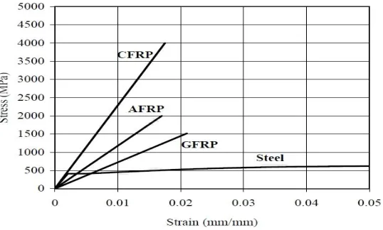
composites have significantly higher strength-to-weight ratio than metals and other construction materials. In addition, these materials are non-corrosive, non-magnetic, and generally resistant to chemicals. A comparison among carbon FRP, aramid FRP
(AFRP), and glass FRP (GFRP) sheets(based on fiber area only), and reinforcing steel
in terms of stress strain relationship is illustrated in next figure
[image:19.612.199.468.217.379.2]
Figure .2.1: Comparison among CFRP, AFRP, and GFRP sheets and reinforcing steel in terms of stress-strain relationship.
2.2.3 Types of CFRP
There are three types of CFRP
GFRP -Glass fibers typically have a Young modulus of elasticity (70 GPa for E-glass)
lower than carbon or aramid fibers and their abrasion resistance is relatively poor. In
performance (static and dynamic) of the composite material. FRP composites based on fiberglass are usually denoted as GFRP.
AFRP–Aramid fibers are organic fibers, made of aromatic polyamides in an extremely
orient form. Due to the anisotropy of the fiber structure, compression loads promote a localized yielding of the fibers resulting in fiber instability and formation of kinks.
Aramid fibers may degrade after extensive exposure to sunlight, losing up to 50 % of their tensile strength. In addition, they may be sensitive to moisture. Their creep behavior is similar to that of glass fibers, even though their failure strength and fatigue behavior is higher than GFRP. FRP composites based on aramid fibers are usually denoted as CFRP. For strengthening purposes in civil engineering carbon fibers are the most suitable.
CFRP-Carbon fibers are used for their high performance and are characterized by
high Young modulus of elasticity as well as high strength. They have an intrinsically brittle failure behavior with a relatively low energy absorption; nevertheless, their failure strength are larger compared to glass and aramid fibers. Carbon fibers are less
sensitive to creep rupture and fatigue and show a slight reduction of the long-term tensile strength. FRP composites based on carbon fibers are usually denoted as CFRP.
2.2.4 The uses of FRP
FRP composites can be produced by different manufacturing methods in many shapes and forms. The most popular ones for concrete reinforcement are bars, prestressing tendons, pre cured laminates shells, and fiber sheets. FRP bars and tendons are currently produced with sizes and deformation patterns similar of those of steel bars, strands and solid wires.
They are commonly used for internal concrete reinforcement. FRP pre-cured
1) To resolve corrosion problems in reinforcing steel
2) To increase the efficiency of repair work for the deteriorating RC infrastructure, professionals have turned to alternative materials such as FRP composites.
3) The interest in the use of composites is attributable to declining manufacturing costs combined with ease and speed of installation.
The structural design and thus the production of structural elements made of reinforced concrete is based on forces and loads current in codes of the time. However, during the service life of a structure, various circumstances may require that the service loads are changed due to:
1) A modification of the structure: cutting of holes in slabs or beams. 2) A different use of the structures: from offices to library.
3) Ageing of the construction materials.
4) Deterioration of the concrete caused by reinforcement corrosion. 5) Cutting of pre- or post- stressed reinforcement cables.
6) Fire damages.
7) Upgrading of building codes. 8) Earthquake design requirements.
The CFRP laminates are used for the post-strengthening of structures to increase the load bearing capacity of structural components (increase of bending tensile force). The increased flexural capacity results in reduced deflections and the reduction in crack propagation. The use of carbon fiber plate has distinct advantages over the use of
2.2.5 Advantages and disadvantages of FRP
Advantages of FRP reinforcement:
1) High longitudinal tensile strength (varies with sign and direction of loading relative to fibers)
2) Corrosion resistance (not dependent on a coating) 3) Nonmagnetic
4) High fatigue endurance (varies with type of reinforcing fiber) 5) Lightweight (about 1/5 to 1/4 the density of steel)
6) Low thermal and electric conductivity (for glass and aramid fibers)
Weight advantages
another very distinct advantage of FRP is it is low weight to strength ratio as rule of thumb for the same strength FRP will weigh approximately one seventh as much as steel, and half as much as aluminum. Light weight properties are important when considering the cost and ease of installation especially for pipe and tanks. FRP’s
inherent light weight is an advantage when equipment must be mounted on existing structures such as scrubbers on mezzanines applications such as FRP tank trailers.
High Strength
Economy
Often, a major advantage of FRP is it is lower cost. When comparing materials for corrosion service, rubber lining, titanium, and the exotic stainless materials are very frequently alternatives to FRP. In these cases, FRP may offer both a satisfactory solution
to corrosion problems and the lowest of FRP with other materials. These costs depend entirely upon the application, the design consideration, the pressures (or vacuums) involved, and the product configurations. FRP is not competitive, however, if you simply try to substitute it for a carbon steel in a particular use, with minimum design changes. Design for FRP as a material of its own-not as a substitute for another material (as you might substitute stainless for carbon steel).
2.2.6 Disadvantages of FRP reinforcement
The disadvantages of FRP reinforcement are as follows: 1) No yielding before brittle rupture
2) Low transverse strength (varies with sign and direction of loading relative to fibers). 3) Low modulus of elasticity (varies with type of reinforcing fiber).
4) Susceptibility of damage to polymeric resins and fibers under ultraviolet radiation exposure.
5) Low durability of glass fibers in a moist environment.
6) Low durability of some glass and aramid fibers in an alkaline environment.
7) High coefficient of thermal expansion perpendicular to the fibers, relative to concrete. 8) May be susceptible to fire depending on matrix type and concrete cover thickness.
2.3 Shear strength of reinforced concrete using FRP
throughout the world are in urgent need of repair or reconstruction because of deterioration due to corrosion of their steel reinforcements, insufficient shear reinforcement resulting, design errors, use of outdate codes, increase in demand of service load, and construction defects and design faults .
The application of Carbon Fiber Reinforced polymer Composite material, as an
external reinforcement is a viable technology recently found to be worth for improving
the structural performance of reinforced concrete structures (Chu kia wang, sixth edition,
1998)
2.3.1 The equation used to calculate shear strength
2.3.1.1 ACI Code provisions for shear strength of Beams
The nominal shear strength Vn:
Vn = Vc +VS
Where:
Vc is the nominal shear strength provided by concrete.
Vs is the nominal shear strength provided by steel shear reinforcement. Therefore, ACI 318-95 allows the use of the following simplified equation.
𝑉𝑐 = 1
6 𝑓´𝑐 𝑏𝑤𝑑
The nominal shear reinforcement contribution, Vs, is based on the 45-degree-truss model and where vertical stirrups, (stirrups perpendicular to the axis of member are used
The ACI 318-95 limits Vs to 0.67√ (f-c b w d). In addition, a minimum amount of web
reinforcement, Av (min.), has to be provided if the applied shear force, Vu, exceeds half of the factored inclined cracking shear, φ (0.5Vc).
𝐴𝑣 𝑚𝑚 = 𝑏𝑤 𝑠 3𝑓𝑦
The stirrups are unable to resist shear failure unless they are crossed by an inclined crack. For this reason .ACI Section-11-5-4-1 sets the maximum spacing of vertical
stirrups as the smaller. When d/2 or 610 mm if Vs ≤ 1/3√(fc' b w d) and when d/4 or
305 mm if Vs >13√f'c b w d (Chu kia wang, sixth edition, 1998)
2.3.1.2 Khalifa Equation
Shear Strength of RC Beams Strengthened with FRP Reinforcement:
The nominal shear strength of a RC beam may be computed by the basic design equation presented in ACI 318-95 and given below:
Vn = Vc + Vs
In this equation the nominal shear strength is the sum of the shear strength of the concrete (which for a cracked section is attributable to aggregate interlock, dowel action of the longitudinal reinforcement, and the diagonal tensile strength of the uncracked portion of concrete) and the strength of the steel shear reinforcement. In the case of beams strengthened with externally bonded FRP sheets, the nominal shear strength may be computed by the addition of a third term to account for the contribution of the FRP sheet to the shear strength in this equation.
The design shear strength is obtained by multiplying the nominal shear strength by a strength reduction factor, φ. It is suggested that the reduction factor of φ = 0.85 given in
ACI 318-95 be maintained for the concrete and steel terms. However, the reduction factor for CFRP reinforcement will require an adjustment as discussed later.
In order to compute the nominal shear strength as given in the last equationit is
necessary to quantify the contribution of CFRP reinforcement to the shear capacity (Vf). The contribution of CFRP depends on several parameters including the stiffness of the CFRP sheet, the quality of the epoxy resin, the compressive strength of the concrete, the number of layers of CFRP sheet, the wrapping scheme, and the fiber orientation angle. It has been difficult to establish one formula to compute (Vf) because the parameters are numerous and there is a lack of adequate experimental results. This study presents two equations that may be used to obtain Vf and suggests taking the lower of the two results as the shear strength contribution of the CFRP reinforcement. These two equations represent two possible failure modes.
The first of the two failure modes is CFRP rupture. Based on the experimental results and concepts presented by Triantafillou (Oct 1997), CFRP rupture occurs at an average stress level below the ultimate strength of CFRP due to stress concentrations. This average stress level, the effective stress, may be determined from experimental results comparing the stiffness of the CFRP sheet used in various strengthening efforts. Due to a lack of experimental results, this method does not, however, address the effect of concrete strength or bonded surface configuration on the shear capacity.
V n = V c + Vs + V f
𝑉
𝑓=
A
ff
fcsinβ + cosβ ∗ d
fs
f≤
2 f′
cb
wd
Where:
V f = the shear contribution of the CFRP, Vs is the shear strength of the steel
reinforcement and V c is the shear strength of the concrete.
f
fc = effective tensile stress in the FRP sheet in the direction of the principal fibersd
f= effective depth of the CFRP shear reinforcement (usually equal to d for rectangularsections and for T-sections).
s
f = spacing of FRP stripsA
f = area of CFRP shear reinforcementβ =
angle between the principal fiber orientation and the longitudinal axis of the beamf 'c= concrete compressive strength in MPa
bw = width of the web of beam cross section
2.4 Finite element analysis
H.-T. Hu et al. (2004) numerical analyses are performed using the ABAQUS finite element program to predict the ultimate loading capacity of rectangular reinforced concrete beams strengthened by fiber-reinforced plastics applied at the bottom or on both sides of these beams., and fiber-reinforced plastics is simulated using appropriate
constitutive models. The influences of fiber orientation, beam length and reinforcement
ratios on the ultimate strength of the beams are investigated. It has been shown that the use of fiber-reinforced plastics can significantly increase the stiffnesses as well as the ultimate strengths of reinforced concrete beams.
and some strengthening schemes are discussed in detail for engineering applications. It has been shown that the use of fiber-reinforced plastics can significantly increase the stiffness as well as the ultimate strengths of reinforced concrete slabs.
W et al. May, (2010) this thesis details experimental work and finite element simulations of reinforced concrete beams retrofitted with carbon fiber reinforced polymer (CFRP). The objectives of this study were to investigate the behavior of retrofitted beams experimentally, develop a finite element model describing the beams, verifying the finite element model against the experimental results and finally investigating the influence of
different parameters on the behavior of the retrofitted beams. The ABAQUS program
was used to develop finite element models for simulation of the behavior of beams. The concrete was modeled using a plastic damage model and two models, a perfect bond model and a cohesive model, were evaluated for the concrete-CFRP interface.
R.D et al. 7(2007) this paper presents the numerical study on and retrofitted reinforced concrete beams subjected to combined bending and torsion. Different ratios between twisting moment and bending moment are considered. The finite elements adopted by ANSYS are used for this study. For the purpose of validation of the finite element model developed, the numerical study is first carried out on the reinforced concrete beams that were experimentally tested with carbon fiber reinforced plastic composites with ±45o
2.5 Conclusion
It is known that the steel is common in the use of concrete structures, and it has some advantages in the concrete works but also there are some disadvantages when used the steel in concrete structure. But With the passage of time was discovered Fiber reinforced
CHAPTER 3
RESEARCH METHODOLOGY
3.1 Introduction
This chapter elaborates the process that was conducted in fulfilling the objectives of the project. It also discuss about the data requirements, data collection, properties of used materials and beams. This study analyzed 5 beams using the ABAQUS finite element program to predict the ultimate loading capacity of reinforced concrete continuous beams strengthened by CFRP applied at different orientation. A total of five beams were analyzed where one of them was treated as control specimen while the other four beams were strengthened using CFRP. Table 3.1 shows the information of all beams. This study also compare between results of using ABAQUS finite element program with the
result of experimental work which was done by other student.
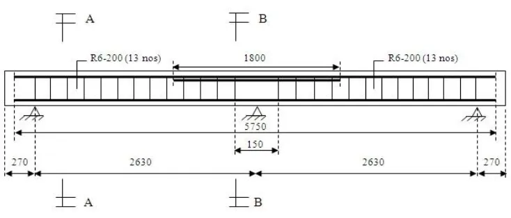
3.2 Beam details
Beam No. 1 is the beam which not strengthened with CFRP and taken as the control specimen. For beam No. 2, it was wrapped with 4 sides of CFRP strips with the
orientation of 900. For beam No.3, it was wrapped with 3 sides of CFRP strips with the
sides of CFRP strips with the orientation of 45/1350. For beam No.5, it was wrapped with 3 sides of CFRP strips with the same orientation as beam No.4. The table 3.1 shows the beams designation while figure 3.1 and 3.2 show the beam details and cross section of the beam respectively. For main reinforcement, high yield strength steel
reinforcement of size 20 mm were while used while for stirrups, mild yield strength of
[image:31.612.112.540.243.498.2]steel reinforcement of size 6mm were used.
Table 3.1: Information of all beams
No of beam av /d CFRP Orientation Wrapping scheme
1
2.5
--- ---
2 0/90 4 sides
3 0/90 3 sides
4 45/135 4 sides
[image:31.612.147.514.494.651.2]5 45/135 3 sides
Figure 3.2: Cross section details
Figure 3.3: Loading Position
Figure 3.4 Cross Section for Fully Wrap (4 sides bonding)
Figure 3.5: Cross Section for 3 Sides Bonding
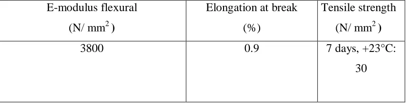
3.3 Materials of the beams
Explain about the compressive strength of concrete used as well as CFRP and epoxy.
Fcu = 30 N/ mm2 Epoxy: sikadur – 330
Table 3.2: Properties of Sikadur-330 (Sika kimia, 2009)
E-modulus flexural
(N/ mm2 )
Elongation at break (%)
Tensile strength
(N/ mm2 )
3800 0.9 7 days, +23°C:
[image:33.612.121.539.408.515.2]3.4 Abaqus software
3.4.1 Introduction to Abaqus/CAE
[image:34.612.243.413.242.494.2]A complete Abaqus analysis usually consists of three distinct stages: preprocessing, simulation, and post processing. These three stages are linked together by files as shown below:
Figure 3.6: preprocessing, simulation, and processing.
Abaqus is a suite of powerful engineering simulation programs based on the finite element method, as Product Life-cycle Management (PLM) software tools. The unique features of Abaqus include:
1) Abaqus contains an extensive library of elements that can model virtually any geometry.
3) various different material models to simulate the behavior of most typical engineering materials including metals, rubber, polymers, composites, reinforced concrete
and resilient foams, and geotechnical materials such as soils and rock.
4) Designed as a general-purpose simulation tool, Abaqus can be used to study more than just structural (stress/displacement) problems.
3.4.2 Starting Abaqus
To start Abaqus/CAE, followed by the Startmenu at computer was click and then chose
from programs Abaqus SE Abaqus CAE. When Abaqus/CAE begins, the Start Session dialog box appears. The following session startup options are available:
1) Create Model Database - to begin a new analysis.
2) Open Database - to open a previously saved model or output database file. 3) Run Script - to run a file containing Abaqus/CAE commands.
4) Start Tutorial - to begin an introductory tutorial from the online documentation.
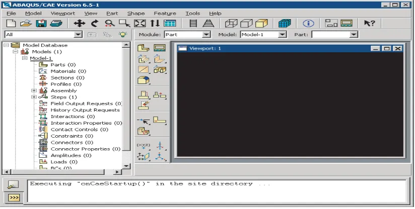
3.4.3 Overview of the main window
3.4.3.1 Components of the main window
Figure 3.7: Components that appear in the main window.
Title bar:The title bar indicates the version of ABAQUS/CAE and the name of the
currentmodel database.
Menu bar:The menu bar contains all the available menus; the menus give access to all
the functionality in theproduct. Different menus appear in the menu bar depending on
which module was selected fromthe context bar.
Toolbar:The toolbar provides quick access to items that are also available in the menus.
Context bar:ABAQUS/CAE is divided into a set of modules, where the module list in
the context bar allows movement between these modules.Other items in the context bar
are a function of the module.
Model Tree:The Model Tree provides a graphical overview of the model and the objects
that itcontains, such as parts, materials, steps, loads, and output requests. In addition, the
Model Treeprovides a convenient, centralized tool for moving between modules and for
References
Adhikary, B. B., & Mutsuyoshi, H. _2004_. “Behavior of concrete beams strengthened
in shear with carbon-fiber sheets.” J. Compos.Constr., 8_3_, 258–264.
Ahmed Mahmud Khalifa. (March 1999).Shear performance of reinforced concrete
beams Strengthened with advanced composites.
Al-Sulaimani, G. J., Istem, A., Basunbul, A. S., Baluch, M. H., & Ghaleb, B. N._1994_. “Shear repair for reinforced concrete by fiberglass plate bonding.” ACI
Struct.J., 91_3_, 458–464.
Alex Li,1 Jules Assih,2 & Yves delmas3 (April 2001).shear strengthening of rc beams
with externally bonded CFRP sheets.
Bousselham, A., & Chaallal, O. _2004_. “Shear strengthening reinforced concrete
beams with fiber-reinforced polymer: Assessment of influencing parameters and required research.” ACI Struct. J., 101_2_, 219–227.
Bousselham, A., & Chaallal, O. _2004_. “Retrofit of reinforced concrete T-beams in
shear with U-shaped CFRP wrap.” Proc., 4th Int. Symp. On Advanced Composite Materials in Bridges and Structures, Canadian Society for Civil Engineering _CSCE_, Calgary, Alta., 8.
Professor Carlo Pellegrino (June 2009).Flexural Strengthening of Reinforced Concrete
Beams with Prestressed FRP.
Chu kia Wang. (1998).sixth edition. reinforced concrete design.
Gamage, J.C.P.h, wong, M.B & Al mahidi R. (2005).Performance of CFRP
Godat, A., Neale, K. W., & Labossière, P. _2007b_. “Towards modeling FRP shear- strengthened reinforced concrete beams.” Proc., 8th Int. Symp. on Fiber
Reinforced Polymer Reinforcement for Concrete Structures, University of Patras, Patras.
Hsuan-Teh Hu *, Fu-Ming Lin, Yih-Yuan Jan (2004).Nonlinear finite element analysis
of reinforced concrete beams strengthened by fiber-reinforced plastics
H. K. Lee†, S. K. Ha et al (2008).Finite element analysis of shear-deficient RC beams
strengthened with CFRP strips/sheets.
Jayabrakash, (August 2006).Shear strengthening of reinforced concrete beams using
externally bonded BI- directional carbon fiber reinforced polymer.
Khalifa, A., & Nanni, A. _2000_. “Improving shear capacity of existing RC T-section
beams using CFRP composites.” Cem. Concr. Compos., 22_3_, 165–174.
Leung, C., Chen, Z., Lee, S., Ng, M., Xu, M., and Tang, J. _2007_. “Effect of size on the
failure of geometrically similar concrete beams strengthened in shear with FRP strips.” J. Compos. Constr., 11_5_, 487–496.
Liu Zihong, (July 2007).Testing and analysis of a fiber reinforced polymer”.
Mohamed Sh Mahmud (2009).Finite Element Modeling Reinforced Concrete Beams
Strengthened with FRP Laminates.
Nabil F. Grace (May-June 2001).Strengthening of negative moment region of
Santhakumar, R., Chandrasekaran, E., & Dhanarraj, R. _2004_. “Analysis of retrofitted reinforced concrete shear beams using carbon fiber composites.” Electron. J. Struct. Eng., 4, 66–74.
Shahawy, M., & Beitelman, T. E. ~2000!. ‘‘Static and fatigue performance of RC
beams strengthened with CFRP laminates.’’ Rep., Structural Research Center,
Florida Dept. of Transportation, Tallahassee, Fla.
Triantafillou, T. C. _1998_. “Shear strengthening of reinforced concrete beams using
epoxy-bonded FRP composites.” ACI Struct. J., 95_2_, 107–115.
Wong, R. _2001_. “Towards modeling of reinforced concrete members with externally
bonded fiber reinforced polymer _FRP_ composites.” MS thesis, Univ. of
Toronto, Toronto, Ont.
ACI 440.2R, 2008, “Guide for the Design & Construction of Externally Bonded FRP