Fault Location Method and Simulation Analysis of
Parallel Compensating Capacitors
Daquan Du1, Na Zheng2, Zhiming Su3
1
Hebei Electric Power Research Institute, Shijiazhuang of Hebei, China
2
Hebei Shijiazhuang Power Supply Company, Shijiazhuang of Hebei, China
3
School of Electrical and electronic engineering, North China Electric Power University, Baoding of Hebei, China Email: [email protected]
Received March, 2013
ABSTRACT
At present, the operational parallel compensating capacitors can only through the protection action for the information, so we can‘t location the fault capacitor. In order to obtain every parallel capacitor running status information and meanwhile according to internal structure and the operation mode of film capacitor, this paper established the physical model on the single capacitor and the capacitors and simulated different forms of capacitor fault model and calculated currents changes which flow through the capacitor in every group. According to the above situation, we established fault criterion matrix of capacitors. The simulation results show that the fault criterion matrix can reflect capacitor run-ning state information accurately, and it positioned fault capacitor effectively.
Keywords: Parallel Capacitor; Physical Model; Fault Location; Fault Matrix
1. Introduction
As a kind of very important reactive power compensation equipment, capacitor improved the power system struc-ture and the power quality. The stable operation of ca-pacitors is a very important guarantee for the power sys-tem security.
At present, the transformer substation under the juris-diction of the power supply company, which has large numbers of capacitor. So it is difficult to monitor single capacitor’s electric capacity effectively in the operation and maintenance. When the capacitor failure occurs, only relying on capacitor protection device movement, this method is an afterthought method, and only reflects the fault information of the capacitors. Location the fault capacitor need for detected individually[1-3].
Currently, the running parallel capacitor is lack of ef-fective online testing means. Reference [4] applied high potentials in taking energy and wireless synchronization acquisition and transmission technology to design a par-allel capacitor’s capacitance online monitoring system. Based on the each current flow through capacitor, we can realize the change trend of every capacitor’s capacitance.
In order to obtain the capacitor in the parallel capacitor banks operating status information and locate on the fault capacitor effectively, this paper modeled a single capaci-tor and the entire group of capacicapaci-tors physical model, which according to the internal structure of the film
ca-pacitors and field operation. We simulated different forms of capacitor fault model and calculated currents changes which flow through the capacitor in every group. According to the above situation, we established fault criterion matrix of capacitors. The simulation results show that the fault criterion matrix can reflect capacitor running state information accurately, and it positioned fault capacitor effectively.
2. The Internal Structure and Operation
Mode of the Parallel Capacitor
and 4 series, and the rated capacity of each capacitor is 29.55 uF, a discharge coil is used to discharge and cater to the voltage transformer[5].
Capacity of the capacitor changes in two forms, the increase and decrease of the electrical capacity. The ca-pacitance of the capacitor increase is due to the break-down or partial discharge of the internal components and at this time the amount of increase of the electric capac-ity is often at least 10%, even larger. But the reasons for the reduction of the capacitor capacity are element through a larger current, which exceeds the predeter-mined value cause internal fuse blown. If one or two components blown fuse, a change in capacitance value is generally less than 5%.
According to the relevant protocols of the parallel pacitors at current, when the capacity change of the ca-pacitor exceeds a certain threshold value is considered to be the fault of the capacitor. When the capacitor fault occurs, the fuse will be blown and it will isolate fault original from intact original, meanwhile the capacitance of the capacitor will change accordingly. Capacitor ca-pacity changes can be reflected in the current from flow-ing through the capacitor, based on this to determine the operating state of the capacitor from the monitoring of the capacitor current.
3. The Model of Capacitor and Simulation
In order to obtain the run state trend information of ca-pacitor in parallel caca-pacitor bank, we assumed that the internal fuse blown to simulate the electrical capacity
changes in the amount of 5% in this paper. By analyzing the current flowing through the capacitor and according to the relationship between the capacitance of the ca-pacitor and the current value to obtain the trend of the electric capacity of the capacitor and position the capaci-tor whose electrical capacity has a large change.
Modeling capacitor parameters: type BAM12/2-334- 1W, rated voltage 6 kV, rated capacity 29.55 uF and in the form of internal fuse protection. The internal struc-ture of the capacitor is 12 and 4 series as shown in Fig-ure 2.
C C C C
TV
C C C C
TV QG1
[image:2.595.324.520.234.431.2]FV L
Figure 1. Main wiring diagram of the parallel compensation capacitor bank.
[image:2.595.62.533.486.712.2]Capacitor bank shown in Figure 1 as an example, the connection of each group-phase capacitors is 10 and 4 series, and every capacitor is 12 and 4 series in each in-side element. Simulation of the electric capacity change within 5% of the capacitor, it may be has a variety of fusing forms according to different fuse blown fuse[6].
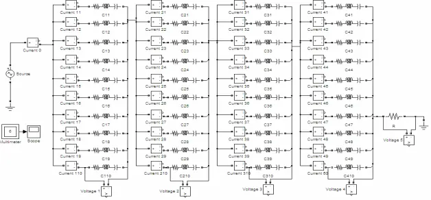
Fault simulation in this paper is based on the Simulink public module library and electricity systems profes-sional module library of the Matlab simulation platform. The Simulink simulation language is one of the most famous integrated simulation environment in the field of dynamic system simulation, also it uses advanced graph-ics technology, has a good user interface, provides a large number of systems built-in modules, simulation concise and practical[7].
3.1. The Fuse Blown Only Occurs in a Capacitor
The equivalent diagram of single capacitor shown in
Figure 2, the connection of elements is 12 and 4 series, and the capacity of the capacitor is 29.55 uF. Assuming that the each element of capacitor has the same capacity, a capacitance value of each element can be calculated as 9.85 uF according to the series-parallel relationship of the capacitive element.
As shown in Figure 2, the connection relationship of each capacitor element has obvious symmetry, when there is a blown fuse, we assume L11 fuse (denoted as case 1), according to the series-parallel relationship of capacitance the value of the capacitor can be calculated as 28.8933uF. When the two fuse are blown, it is as-sumed that L11 and L12 at the same time fuse (denoted as case 2), or L11 and L21 at same time fuse (denoted as case 3), the electrical capacity of the capacitor reduce to 28.2652 uF and 28.1429 uF respectively.
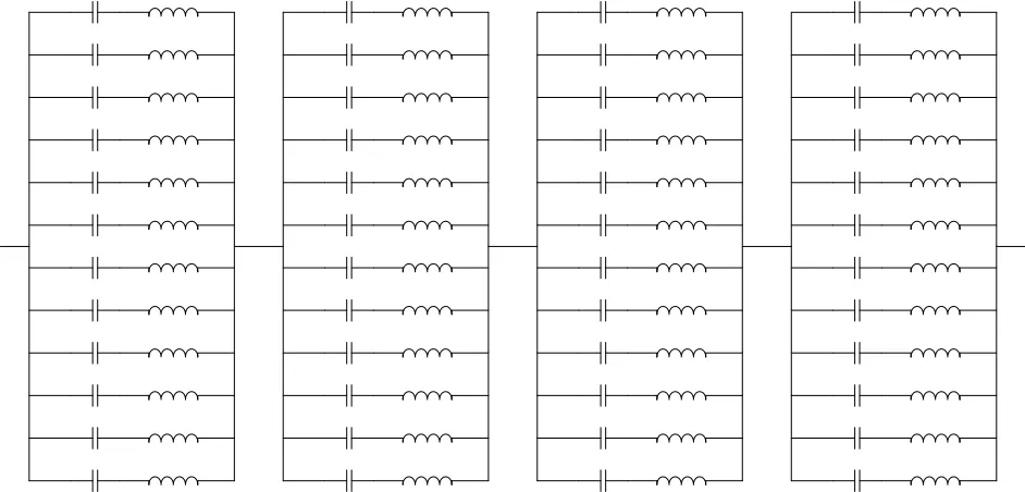
The single-phase equivalent circuit of 10 and 4 series capacitor is shown in Figure 3. Apply Simulink tool to simulate and calculate the current flowing through the capacitor bank shown in Figure 3. Assuming the blown fuse occurs in the C11 capacitor, and we denoted the current which flowing through C11 as I11, and C12 as I12, and the current following other capacitors and so on. Current calculation results shown in table 1, I11 is the current flowing in the failure capacitor, and I12 is the current flowing in non-failure of a capacitor of the fault parallel segments, I21, I31, I41 are current flowing through the other parallel section capacitor. Figure 4 is a curve, which reflects the relationship between the current flowing through capacitor and capacitance change.
[image:3.595.143.457.402.548.2]From Table 1 and Figure 4, the calculated result, we
[image:3.595.57.284.578.707.2]Figure 3. Single-phase equivalent circuit of the 10 and 4 series capacitor bank.
[image:3.595.308.540.591.731.2]Figure 4. Curve reflects the relationship between the cur-rent and capacitance change.
Table 1. Current flowing through capacitor.
I11 I12 I21 I31 I41 Total current
No fault 33.154 33.154 33.154 33.154 33.154 397.842
Case 1 32.462 33.200 33.138 33.138 33.138 397.658
Case 2 31.799 33.244 33.123 33.123 33.123 397.481
can see in the three fault case, the currents flowing through the failure of a capacitor are reduced, which is same as trend of the capacitor capacity.
3.2. The Fuse Blown Happens in Different Capacitors
Such cases mainly consider the fuse blown in two ca-pacitors, because the connection of the capacitor group is 10 and 4 series, and taking the symmetry of the capacitor connected relationship into account, there are two cases in the failure of a capacitor:
1) Two failure capacitors occur in a same series, may set as C11 and C12;
2) Two failure capacitors occur in the different series, may set as C11 and C21;
While a change in capacitance of each capacitor has three forms, i.e. a blown fuse in the element(case 1 in 2.1), two blown fuse in the same series (case 2 in 2.1) and two blown fuse in the different series (case 3 in 2.1). The different points of the three fuse case only a reduc-tion of the capacitor capacitance values are different, but have the same regularity, so only consider the first two cases described above analyze. The current variation in other circumstances can be got in the same way.
Apply Simulink tool to simulate, and compare no fault current and fault current flowing capacitor group, the results shown in the table below.
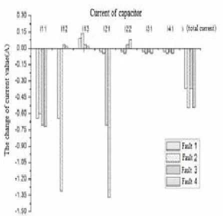
In Table 2, the failure capacitors of the fault 1 are C11 and C12, the failure capacitors of the fault 2 are C11 and C12, the failure capacitors of the fault 3 are C11 and C21, the failure capacitors of the fault 4 are C11 and C21. As can be seen from Figure 5 When the capacitor failure occurs, the change of current is very obvious compare with the normal capacitor current, and total current of the capacitor bank will has a dramatic change correspond-ingly, and the current change in no fault capacitor is very small.
4. Fault Location of Capacitor
The relationship between a change in capacitance and the current flowing through the capacitor bank can be ob-tained in section II. Current changes can be demonstrated in the form of a matrix, for the previous embodiment the capacitor bank can be established a 10-row by 4 column matrix, and we defined that when the capacitor current increases the value of the corresponding position is 1, when the capacitor current is decreased the value of the corresponding position is -1.we can judge the fault of the capacitor bank through observing the change of the ma-trix values easily. If we need to know the fuse number of the capacitor element, we can judged by reduce or in-crease of the current.
[image:4.595.312.535.300.516.2] [image:4.595.90.508.562.737.2]Established discrimination matrix based on data in
Table 2, the four fault a matrix as follows:
Figure 5. Comparison of each capacitor current changes.
Table 2. Current flowing through each capacitor.
I11 I12 I13 I21 I22 I31 I41 I(total current)
No fault 33.154 33.154 33.154 33.154 33.154 33.154 33.154 397.842
Fault 1 C11(case 1)
C12(case 1) 32.507 32.507 33.246 33.123 33.123 33.123 33.123 397.473
Fault 2 C11(case 1)
C12(case 2) 32.550 31.843 33.290 33.108 33.108 33.108 33.108 397.296
Fault 3 C11(case 1)
C21(case 1) 32.447 33.184 33.184 32.447 33.184 33.123 33.123 397.474
Fault 4 C11(case 1)
1
1 1 1 1
1 1 1 1
1 1 1 1
1 1 1 1
1 1 1 1
1 1 1 1
1 1 1 1
1 1 1 1
1 1 1 1
1 1 1 1
A 2
1 1 1 1
1 1 1 1
1 1 1 1
1 1 1 1
1 1 1 1
1 1 1 1
1 1 1 1
1 1 1 1
1 1 1 1
1 1 1 1
A 3
1 1 1 1
1 1 1 1
1 1 1 1
1 1 1 1
1 1 1 1
1 1 1 1
1 1 1 1
1 1 1 1
1 1 1 1
1 1 1 1
A 4
1 1 1 1
1 1 1 1
1 1 1 1
1 1 1 1
1 1 1 1
1 1 1 1
1 1 1 1
1 1 1 1
1 1 1 1
1 1 1 1
A
The working condition of the individual capacitors in the capacitor group can be seen from 4 matrixes above. When the matrix value in a column is the same show that the respective capacitors segments have no faults; when the positive and negative value appear in a column in the discrimination matrix it shows that has a fault in this ca-pacitor section, and the capacitance value is reduced in the corresponding position of negative value, shows that the capacitor internal fuse has blown. According to the current changes and its corresponding relationship, we can determine the number of fault capacitor fuse blown.
5. Conclusions
In order to obtain operating state information and the failure of a capacitor effectively positioning of the vari-ous capacitors in shunt capacitor bank, and according to the operation mode and the capacitor’s internal structure we establish the physical modeling of a single capacitor and the entire group of capacitors in this paper, and
si-mulate different form of capacitor failure model, and calculate the change current flowing through the capaci-tor bank, and establish the failure discrimination matrix on this basis. The simulation results show that the ca-pacitor failure discrimination matrix can reflect the run-ning state of the capacitor in the group accurately, and locate the failure capacitor effectively.
6. Acknowledgements
The paper is supported by the opening funding of Na-tional Engineering Laboratory for Ultra High Voltage Engineering Technology (Kunming, Guangzhou).
REFERENCES
[1] T. Zhao, Y. P. Liu and F. C. Lv, “A Feasibility and Method Research on the On-line Monitoring of Parallel Compensation Capacitors,” Proceeding of 2012 IEEE In-ternational Conference on Condition Monitoring and Diagnosis, September 2012, Bali, Indonesia, pp. 748-751.
doi: /10.1109/CMD.2012.6416255
[2] A. Lu, “Power Station Substation and Power System Re-active Power,” China Electric Power Press, 2006, pp. 146-156.
[3] Q. L. Jia, D. L. Yuan and Y. F. Luan, “System Simulation, Analysis and Design based on Matlab7.X/Simulink/ Stateflow,” Xi'an University Press,2008
[4] Z. X. Han and Q. Y. Wu, “Power System Analysis,” Zhejiang University Press, 2003, pp.11-13.
[5] D. Maurizo, P. G. Gianpietro, P. Marannino, et a1., “Op-timal Capacitor Placement Using Deterministic and Ge-netic Algorithms,” IEEE Trans on Power System, Vol. 15, No. 3, 2000, pp. 1041-1046. doi:10.1109/59.871731
[6] T. W. Rudy, “High Speed Reactive Compensation Sys-Tems For Industrial Applications,” Cement Industry Technical Conference, IEEE-IAS/PCA, Vancouver, BC, Canada, 2001, pp. 41-50.