Full Length Research Article
DESIGN OF DUAL MODE FUZZY LOGIC LOAD FREQUENCY CONTROLLER FOR INTERCONNECTED
POWER SYSTEMS USING SUPERCONDUCTING MAGNETIC ENERGY STORAGE UNIT
*Vinoth Kumar, N. J., Sathya, M. R. and Mohamed Thameem Ansari, M.
Department of Electrical Engineering, Annamalai University, Annamalai Nagar – 608002, Tamilnadu, India
ARTICLE INFO ABSTRACT
A design of dual mode fuzzy logic load frequency controller for interconnected two area thermal power systems with superconducting magnetic energy storage (SMES) unit is proposed in this paper. Nowadays due to increase in size, increased demand and complexity in interconnected power system, load frequency controller has become more significant. SMES technology has the potential to bring real power storage characteristics to the utility transmission and distribution systems. In general proportional and integral (PI) controllers are used for load frequency control, which is generally tuned on the basis of classical approaches. Proportional and Integral controller are slow and lack of efficiency in handling system nonlinearities. Hence it is much more needed to have controllers which are capable of self tuning in nature according to situations. Dual mode concept is incorporated in the proposed controller because it can improve the system performance. The system with the proposed controller was simulated and the frequency deviation resulting from a step load disturbance is presented. The comparison of proportional plus integral controller, fuzzy logic dual mode controller with SMES unit shows that, with the application of dual mode fuzzy logic controller, the system performance is improved significantly. In this paper, simulation results are carried out for a two area thermal reheat power system. The proposed controller is also found to be less sensitive to changes in the parameters of the system.
Copyright © 2014 Vinoth Kumaret al. This is an open access article distributed under the Creative Commons Attribution License, which permits unrestricted use, distribution, and reproduction in any medium, provided the original work is properly cited.
INTRODUCTION
Load-frequency control (LFC) in power systems is very important in order to supply reliable electric power with good quality. The goal of LFC is to maintain zero steady state errors in a multi-area interconnected power system (Kothari et al., 1989). In addition, the power system should fulfil the requested dispatch conditions. With an increasing demand for electric power the electric power system becomes more and more complicated. Therefore the supply of electric power with stability and high reliability is required. The power system operates in normal state which is characterized by constant frequency and voltage profile with certain system reliability. A number of control strategies have been employed in the design of load frequency controllers (Sheirah and Abd, 1984; Bhatta Praghnesh et al., 2010; Zribi et al., 2005; Ramar and Velusami, 1989; Velusami and Chidambaram, 2007; Toulabi
et al., 2014; Mehdi Rahmani and Nasser Sadati, 2013; Hamed
Shabani et al., 2013) in order to achieve better dynamic performance.
*Corresponding author: Vinoth Kumar, N. J.,
Department of Electrical Engineering, Annamalai University, Annamalai Nagar – 608002, Tamilnadu, India
Among the various type of load frequency controllers, the most widely employed is the conventional proportional integral (PI) controller. Conventional controller can be simple for implementation but takes more time for control and gives large frequency deviation. In recent years fuzzy logic controller has received increasing attention in power system engineering. Fuzzy logic is a logical system for formalization of approximate reasoning, and is used synonymously with fuzzy set theory systems introduced by Zadeh and investigated further by many researchers (Dipti Srinivasan et al., 1995;Gang Feng, 2006; Ertugrul Cam, 2007). Fuzzy logic systemprovided as excellent frame work to more completely andeffectively model uncertainty and imprecision in human reasoning with the use of linguistic variable with membership functions. Fuzzification offers superior expressive power, greater generality, and in improved capability to model complex problems at a low solution cost. Energy storage is an attractive option to augment demand side management implementation. By using energy storage systems, a low cost source of electricity can be efficiently provided to meet the peak demand. An energy storage device can be charged during off-peak period and the stored energy is used during peak period. SMES is suggested as storage unit for improving the
ISSN:
2230-9926
International Journal of Development Research
Vol. 4, Issue, 3, pp. 654-658, March,2014
DEVELOPMENT RESEARCH
Article History:
Received 08th January, 2014
Received in revised form 11th February, 2014
Accepted 15th February, 2014
Published online 14th March, 2014
Key words:
Two area power system, Load frequency control, PI controllers,
Dual mode fuzzy logic controller, Performance Index,
dynamic performance of load frequency control for a two area power systems. A SMES device is a dc current device that stores energy in the magnetic field. The dc current flowing through a superconducting wire in a large magnet creates the magnetic field (Chen and Liu, 2006). Since energy is stored as circulating current, energy can be drawn from the SMES unit with almost instantaneous response with energy stored or delivered over periods ranging from a fraction of a second to several hours. In this study, a two area power system using SMES unit is considered to control power flows. In each control area, all generators are assumed to form coherent group. This paper proposes by taking advantage of the superior characteristics inherent in the design of dual mode fuzzy logic load frequency controller, using superconducting magnetic energy storage device for interconnected power systems. An important design concept of dual mode control is incorporated in the proposed controller because it improves the system performance and makes it flexible for application to actual systems (Chen and Liu, 2006). The computer simulation results of application of the proposed controller with inter connected power systems prove that the proposed controller is effective and provides significant improvement in the system performance.
Statement of the problem
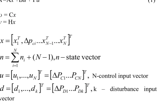
The state variable equation of the minimum realization of the continuous model of the ‘N’ area interconnected power system is expressed as (Velusami and Chidambaram, 2007)
̇=Ax +Bu + d (1)
= Cx
y = Hx
T
T N T N ci Tx
x
p
x
x
1,
...
1...
N
i
i
N
n
n
n
1
vector
state
),
1
(
u
1,...,
u
N
T
P
C1...
P
CN
T,
u
N-control input vector
d
1,...,
d
k
T
P
D1...
P
Dk
T,
d
k – disturbance inputvector
where A is the system matrix, B is the input distribution matrix, is the disturbance distribution matrix, C is the control output distribution matrix, H is the measurable output distribution matrix, x is the state vector, u is the control vector and d is the disturbance vector of load changes.
Description of Dual Mode Fuzzy Logic Controller
The block diagram of dual mode fuzzy logic controller is shown in Fig.1. The major difference between the proposed dual mode fuzzy logic controller and the conventional fuzzy logic controller is that a dual mode fuzzifier module is inserted in the proposed controller. This proposed controller operates in mode A as long as the significant observed variable to the control actions the system output error is sufficiency large i.e greater than the switching limit of the controller otherwise it operates in mode B. Mode A acts as proportional fuzzy logic controller and mode B as integral fuzzy logic controller. Thus,
[image:2.595.318.549.194.310.2]the control structure of the system is changed when switching in each mode of operation. Since the proposed controller is designed based on the switching limit of the controller, the performance of the controller is improved significantly. The fuzzy inference system implement a non-linear mapping from its input space to output space. This mapping is accomplished by a number of fuzzy if-then rules, each of which discussing the local behaviour of the mapping. The rule base is given in table.1. The defuzzification module convert fuzzy value to crisp value. In this paper centroid method is employed for defuzzification.
[image:2.595.323.544.354.408.2]Fig.1. Block diagram of dual mode fuzzy logic controller
Table 1. Rule base for fuzzy logic controller
ACE
ACE N_ Zo P+
N_ P+ P+ Zo
Zo P+ Zo N_
P+ Zo N_ N_
Description of Superconducting Magnetic Energy Storage
The schematic diagram of SMES unit is shown in Fig.2. The SMES unit contains DC superconducting coil and converter which are connected by Y-∆/Y-Y transformer.
Fig. 2. Schematic diagram of SMES unit
The control of the converter firing angle provides the dc voltage Ed appearing across the inductor to be continuously
varying within a certain range of positive and negative values. Neglecting the transformer and the converter losses, the DC voltage is given by
Ed=2Vdo cosα-2IdRc (2)
Where Ed is DC voltage applied to the inductor (kV), α is
firing angle, Id is the current flowing through the inductor
(kA). Rc is equivalent commutating resistance () and Vdo is
[image:2.595.38.289.406.572.2] [image:2.595.325.538.482.645.2]maximum circuit bridge voltage (kV). Charging and discharging of SMES unit are controlled through change of commutation angle α. If α is less than 90o, the converter act as an inverter mode (charging mode). The inductor current deviation is used as a negative feedback signal in the SMES control loop. So, the current variable of SMES unit is intended to be settling to its steady state value. If the load demand changes suddenly, the feedback provides the prompt restoration of current. The inductor current must be restored to its nominal value quickly after a system disturbance, so that it can respond to the next load disturbance immediately (Ali and Dougal, 2010). The transfer function model of SMES unit with inductor current deviation feedback is shown in Fig.3.
Fig. 3. Transfer Function Model of SMES Control Scheme
Application of Dual Mode Fuzzy Logic Controller for Interconnected Power Systems
The proposed dual mode fuzzy logic controller is applied to interconnected two area reheat based thermal power systems. The simulink block diagram of dual mode for two area with proposed controller is shown in Fig.4.
Fig.4. Simulink Block Diagram of dual mode Fuzzy logic controller for two area Interconnected power system with reheat
turbines
Design of conventional PI controller with output feedback
The conventional PI Controller with output feedback are designed using integral square error (ISE) technique (Velusami and Chidambaram, 2007) and the feedback gains are KP=1.05 and KI=0.09. The system output is sampled at the
normal sampling rate of two seconds and the controller output is also updated at normal sampling rate.
Design of proposed dual mode fuzzy logic Controller with output feedback
Design of proposed dual mode fuzzy logic controller with output feedback scheme is carried out for two area interconnected power systems. Since the switching limit value ε should be greater than the steady state error of the system output ∆ACE with only proportional fuzzy logic controller, it is chosen as 0.004 (ε1=0.004, ε2 =0.004).The input variable of
the proposed controller are ∆ACE (error e) and ∆ ̇CE (change of error ce). Fig.5 shows the membership functions for the input variables (e and ce) scheduled by only three fuzzy sets with the simple shape membership functions linguistically labelled as N-, Zo and P+ distributed over the intervals eЄ (-α,
α), ceЄ (-α, α). The value α=0.1 for fuzzifier module A and α = 0.004 for fuzzifier module B. The output variable u is characterized by three fuzzy sets N-, Zo and P+ over the
[image:3.595.308.541.299.395.2]interval (-0.02, 0.02). The feedback signal is sampled at the normal sampling rate of two seconds and the control output is also updated at normal sample rate.
Fig.5. Membership function of ∆ACE, ∆A ̇E of interval fuzzy logic controller
RESULTS AND DISCUSSION
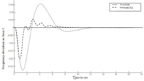
The dual mode fuzzy logic controller designed in the previous section is implemented in an interconnected reheat based thermal power systems. The performance of this controller is simulated for 0.01 p.u. MW step load change in area one and the corresponding frequency deviation f1 in area 1, frequency
deviation ∆f2 in area 2 and tie line power deviation ∆Ptie are
plotted in Fig.6-8. For easy comparison, the responses of f1,
∆f2 and ∆Ptie of the system with the optimum PI controller
designed on the basis of ISE criterion are also plotted in the same Fig.6-8. Similarly the performance of the controller is simulated for 0.01 p.u. MW step load change in area two and the corresponding frequency deviation and tie line power deviation are plotted with respect to time as shown in Fig.9-11.
Fig.6. ∆f1 with step increase in demand of first area with SMES
unit
N_ P+
-α 0 +α
∆ACE, ∆A ̇E Zo
[image:3.595.39.288.455.645.2] [image:3.595.313.551.627.761.2]Fig.7. ∆f2 with step increase in demand of first area with SMES
unit
Fig.8. ∆Ptie with step increase in demand of first area with SMES
unit
Fig.9. ∆f1 with step increase in demand of second area with SMES
unit
Fig.10. ∆f2 with step increase in demand of second area with
SMES unit
Fig.11. ∆Ptie with step increase in demand of second area with
SMES unit
From the result, it is observed that the proposed dual mode fuzzy logic controller has less overshoot and settling time.
Conclusions
This paper presents a new design based on dual mode fuzzy logic controller applicable to an interconnected reheat based thermal power systems using superconducting magnetic energy storage unit. The proposed controller is designed by taking advantage of dual mode control concept and the normal fuzzy sets. Simulation study results of an inter connected power systems reveal that the proposed controller design provides a high quality transient and steady state response. Further, it is also observed that the proposed controller is less sensitive to changes in the parameters of the system. Thus, the overall performance of the proposed controller is found to be superior to that of the conventional PI controllers.
List of Symbols
fi area frequency in Hz
Pei the total power exchange of area i in p.u. MW/Hz
PDi area real power load in p.u. MW
Pci area speed changer output in p.u. MW
XE governor valve position in p.u. MW
PG mechanical (turbine) power output in p.u. MW
kp gain associated with the transfer function of the area in
Hz/p.u. MW
TP area time constant in seconds
R steady state regulation of the governor in Hz/p.u. MW
Tg time constant of the governing mechanism in seconds
kr reheat coefficient of the steam turbine
Tr reheat time constant of the steam turbine in seconds
Tt time constant of the steam turbine in seconds
βi frequency bias constant in p.u. MW/Hz
N number of interconnected areas
∆ incremental change of a variable
S Laplace frequency variable
KP proportional constant
KI integral constant
FLC fuzzy logic controller
ACE, AĊE normalised input variables Min minimum
N_ negative P+ positive
Zo zero
Ptie tie line power
εi switching limit
SMES Superconducting Magnetic Energy Storage
Superscript
T transpose of a matrix
Subscripts
i, j area indices (i, j = 1, 2, . . . , N)
APPENDIX
Data for the interconnected two-area thermal power system,
Kr1=Kr2=0.5;R1=R2=3.2Hz/p.u.Hz;Tg1=Tg2=0.08s;
Tr1=Tr2=10s;a12=-1;ΔPd1=0.01p.u.MW;
Tt1=Tt2=0.3sec;Kps1=Kps2=120Hz/p.u.MW; Tps1=Tps2=20sec;
β1=β2=0.425p.u.MW/Hz; 2πT12=0.545p.u.MW/Hz;
Data for SMES unit,
Ido1=Ido2=4.5KA; Id1min=Id2min=4.0KA; Tdc1=Tdc2=0.03s;
Id1max=Id2max=4.9KA; L1=L2=2.5H.
Acknowledgement
The authors wish to thank the authorities of Annamalai University, Annamalai Nagar, Tamilnadu, India for the facilities provided to prepare this paper
REFERENCES
Kothari M, L., Nanda J, Kothari DP, Das D. Discrete-mode automatic generation control of a two-area reheat thermal system with new area control error. IEEE Trans Power
Syst 1989;4:730–8.
Sheirah M, Abd MM. Improved load frequency self tuning regulator. Int J Control 1984;39:143–58.
Bhatta Praghnesh, Ghoshalb SP, Roy Ranjit. Load frequency stabilization by coordinated control of Thyristor Controlled Phase Shifters and superconducting magnetic energy storage for three types of interconnected two-area power systems. Int J Electr Power Energy Syst 2010;32:1111–24. Zribi, Al-Rashed M, Alrifai M. Adaptive decentralized load
frequency control of multi-area power systems. Int J Electr
Power Energy Syst 2005;27:575–83.
Ramar K. Velusami S. Design of decentralized load frequency controllers using pole placement technique. Electr Mach
Power Syst 1989;16:193-207.
Velusami S. Chidambaram I.A. Design of decentralized biased dual mode controllers for LFC of interconnected power system considering GDB and GRC non-linearities. Energy
Convers Manage 2007; 48: 1691-702.
Toulabi M.R, Shiroei M, Ranjbar A.M. Robust analysis and design of power system load frequency control using the Kharitonov’s theorem. International Journal of Electrical
Power & Energy Systems, 2014; 55:51-58
Mehdi Rahmani, Nasser Sadati. Two-level optimum load frequency control for multi area power systems. .
International Journal of Electrical Power & Energy Systems, 2013; 53:540-54
Hamed Shabani, Behrooz Vahidi, Majid Ebrahimpou. A roboust PID controller based on imperialist competitive algorithm for load-frequency control of power systems. ISA Transactions, 2013; 52:88-95.
Dipti Srinivasan, Liew AC, Chang CS. Applications of Fuzzy Systems in Power Systems. Elect Power Syst Res 1995; 35:39-43.
Gang Feng. A survey on analysis and design of model-based fuzzy control systems. IEEE Trans Fuzzy Syst 2006; 14:676-7.
Ertugrul Cam. Application of fuzzy logic for load frequency control of hydro electrical power plants. Energy Converse Manage 2007;48:1281-8
Chen, L. and Y.Liu. Detailed Modeling of Superconducting Magnetic Energy Storage (SMES) System. IEEE Transactions of Power Delivery 2006;21:699-710..
Ali, M.H., Dougal. R.A. An overview of SMES Applications in Power and Energy Systems. IEEE Transactions on Sustainable Energy 2010;1:38-47.
Demiroren, A., E. Yesil. Automatic Generation control with fuzzy logic controllers in the power system including SMES units. Electrical power and Energy Systems 2004; 26:291-305.
Thameem Ansari M. Md, Velusami S. Dual mode linguistic hedge fuzzy logic controller for an isolated wind-diesel hybrid power system with superconducting magnetic energy storage unit. Energy Convers Manag 2007; 51:169-181.
Tripathy, S.C., M. Kalantar, R. Balasubramanian. Dynamics and stability of wind diesel turbine generators with superconducting magnetic energy storage unit on an isolated power system. IEEE Transactions on Energy Conversion 1991; 6:579-585.