International Journal of Emerging Technology and Advanced Engineering
Website: www.ijetae.com (ISSN 2250-2459, ISO 9001:2008 Certified Journal, Volume 4, Issue 6, June 2014)
652
The Implementation of a Control Circuit for a Microcontroller
Based Automated Irrigation System
Jonathan A. Enokela
1, Isaiah I. Tsavwua
2, Simon A. Onyilo
3Department of Electrical and Electronics Engineering, University of Agriculture, P.M.B. 2373, Makurdi, Nigeria
Abstract--- In many parts of the world especially in arid and semi arid areas, rainfalls, due to their seasonal nature, are inadequate to meet agricultural needs. It thus becomes imperative to use irrigation to meet the moisture needs of plants in order to increase food crop production. The system described here monitors the moisture needs of crops through buried sensors and automatically pumps water for irrigation when the need arises. Through the use of a microcontroller and sensors, water storage and delivery to the farm are automatically carried out thus requiring minimal human interventions, achieving supply of water as needed by plants thus optimizing plant growth and helping to conserve water and energy. The system is very simple to operate and ideally suits the irrigation need of rural farmers.
Keywords--- Automated Irrigation, Microcontroller,
Electronic, Control
I. INTRODUCTION
Crops require moisture to grow. This moisture is provided naturally mostly by rainfalls which are seasonal in many parts of the world. This fact makes the growing of crops to be carried out mostly during the rainy seasons. In the dry seasons crop growing is nearly completely suspended due to the extra difficulties of providing moisture for the crops. In places where dry season farming is carried out the moisture requirements of the crops are most often provided through the method of irrigation.
Irrigation is an artificial means used to supply water to plants for their growth and maturity. In addition to ensuring enough moisture essential for plant life, irrigation also provides insurance against short duration drought and cools the soil and atmosphere to provide a congenial environment for plant growth as well as reducing hazard of soil piping amongst other advantages [1]. Irrigation is carried out mainly through the use of surface or flood irrigation and the drip irrigation type. In the surface irrigation water is applied and distributed over the soil surface by gravity. The drip irrigation allows water to drip slowly to the roots of plants either onto the soil surface or directly onto the root zone through a network of valves, pipes and tubes [2]. The drip irrigation has many advantages over basin flood and localized methods of irrigation [3].
It eliminates the possibility of soil erosion and can be used for the application of liquid fertilizers [4].
The manual method of irrigation is used predominantly by rural farmers in most developing countries especially in areas where the season of rainfall is very short [1].
An automated irrigation system has important advantages over the methods used by the local farmers: it ensures a more precise application and conservation of water, high crop yield as well as removal of human errors [3, 4]. The current trend in irrigation is to shift from manually operated type of irrigation to automated types [4]. Many automated types of irrigation systems that use fairly complex electronics for their control have been implemented. Many of these automated systems use sensors to monitor parameters such as soil moisture, soil temperature, soil pH, leaf temperature, relative humidity, air temperature, rainfall, vapour pressure, and sunshine hours [5]. The use of wireless sensor network technology to implement and control various types of irrigation systems have been reported [2, 5, 6, 7]. The use of wireless and internet communication systems enables real-time monitoring of irrigation systems [8, 9, 10, 11].
Most of the systems that have been reportedly implemented use very complex electronics control and measure very many parameters. The system described here monitors the soil moisture and uses the value of this parameter to schedule the irrigation of a farm. This system is simpler for rural and small-time farmers to adopt than more complicated automatic irrigation scheduling systems that use numerous weather and soil data as inputs.
II. MATERIALS AND METHODS
International Journal of Emerging Technology and Advanced Engineering
Website: www.ijetae.com (ISSN 2250-2459, ISO 9001:2008 Certified Journal, Volume 4, Issue 6, June 2014)
653
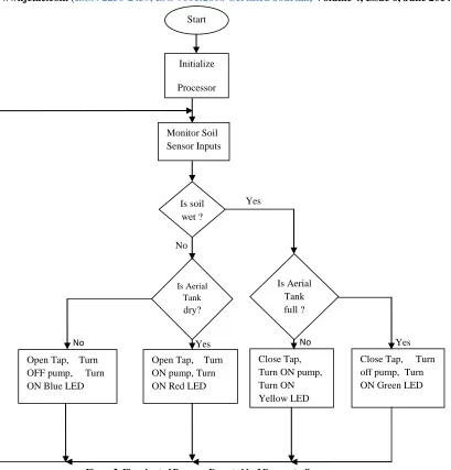
When the system is first switched on, and on sensing that the aerial tank is empty, it turns on the pump, through the ac motor, for the aerial tank to be filled. When this has been done the system checks if the soil is dry upon the affirmation of which the control tap is opened for water to flow to the soil through the sprinkler system. The control tap is closed when the moisture content of the soil reaches a predetermined level that has been fixed by the soil moisture sensors. The aerial tank is then refilled to complete the process. The microcontroller keeps monitoring the state of the sensors to determine what action it will take next.
A.Sensors
Both the water level and the soil moisture sensors are discrete sensing type. The water level sensors are required to indicate the presence or absence of water to an exact height only. We are not interested in the rising or falling of water level outside the stipulated levels. In the same manner the soil moisture sensors are required to indicate only the presence or absence of soil wetness to a predetermined level.
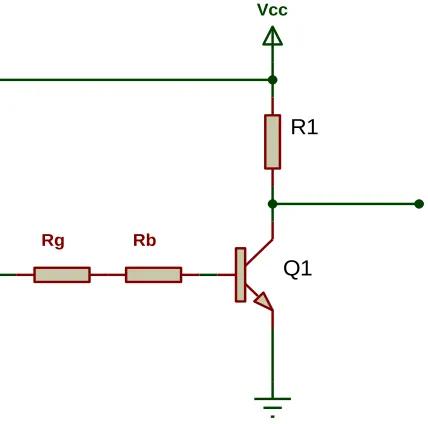
The soil moisture sensors consist of gypsum blocks buried in the soil [12]. Transistors switches are attached to the blocks. The arrangement is shown in figure 2 in which one sensor has been depicted.
The number of sensors employed depends on the size of farm to be irrigated. The logical OR operation of the sensors ensure that all parts of the farm receive adequate moisture. When the soil is dry the gypsum block has a high resistance thus turning off transistor Q1. This transistor is turned on only when the soil has received the desired amount of moisture. If we assume that the resistance of the gypsum block under wet condition is Rg, then the requirement for the saturation of the BJT is expressed as inequality (1).
...(1)
F
I
BI
C
The transistor Q1 will turn on when
1
(
g b)
F CC BEsat...(2)
CC CEsat
R V
V
R
R
V
V
International Journal of Emerging Technology and Advanced Engineering
Website: www.ijetae.com (ISSN 2250-2459, ISO 9001:2008 Certified Journal, Volume 4, Issue 6, June 2014)
654
Figure1: Block Diagram of Automated Irrigation System
AC Power Input Soil Moisture
Sensors
Soil Sensor
Logic
Control
Tap
Sole- noid Drive
Relay
Drive Microcontroller
Status Indicator
Sole- noid
Aerial Tank Water
Level sensors Water
Level Logic
Water Reservoir
Pump
AC Motor
International Journal of Emerging Technology and Advanced Engineering
Website: www.ijetae.com (ISSN 2250-2459, ISO 9001:2008 Certified Journal, Volume 4, Issue 6, June 2014)
655
Q1
R1
Vcc
[image:4.612.64.278.126.338.2]Rg Rb
Figure 2: Schematic Diagram of a Soil Moisture Sensor Unit
International Journal of Emerging Technology and Advanced Engineering
Website: www.ijetae.com (ISSN 2250-2459, ISO 9001:2008 Certified Journal, Volume 4, Issue 6, June 2014)
656
R 4
DC 7
Q 3
G
N
D
1
V
C
C
8
TR 2 TH
6
CV 5
U1
555
Q1
Q2
Q3 R1
R2
R3
R4
R5
R6
VCC
VCC VCC
VCC
VCC
VCC
1
2
TL
1
2
[image:5.612.151.465.140.472.2]TF
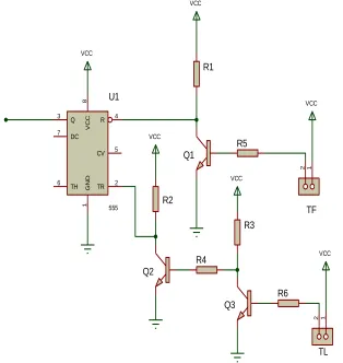
Figure 3: Schematic Diagram of Two-level Water Sensor Unit
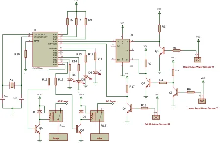
The schematic diagram of the complete automated irrigation system is given in figure 4. The microcontroller used for the project is the PIC16F84A [13]. The microcontroller takes inputs from the soil sensor S1 and the water level sensors (TF, TL) continuously. Under the control
of the program in its memory the microcontroller turns on (or off) the tap or pump depending on the input it has received from the sensors. One of the four LEDs (D1 - D4) is also turned on to visually indicate the state of events at the input of the microcontroller.
Figure 5 gives the flowchart of the program executed by the microcontroller. As indicated in the flowchart the microcontroller polls the input sensors and after taking the appropriate decision it goes back to monitoring the sensors in a continuous loop.
III. RESULTS AND DISCUSSION
International Journal of Emerging Technology and Advanced Engineering
Website: www.ijetae.com (ISSN 2250-2459, ISO 9001:2008 Certified Journal, Volume 4, Issue 6, June 2014)
657
R 4 DC 7 Q 3 G N D 1 V C C 8 TR 2 TH 6 CV 5 U1 555 Q1 Q2 Q3 R1 R2 R3 R4 R5 R6 VCC VCC VCC VCC VCC VCC 1 2 1 2 OSC1/CLKIN 16 RB0/INT 6 RB1 7 RB2 8 RB3 9 RB4 10 RB5 11 RB6 12 RB7 13 RA0 17 RA1 18 RA2 1 RA3 2 RA4/T0CKI 3 OSC2/CLKOUT 15 MCLR 4 U2 PIC16F84AR7 R8 R9
R10 R11 R12 R13 R14 R15 R16 Q4 R17 R18 VCC VCC 1 2 VCC C1 X1 C2 VCC Q5 D1 RL1 VCC1 Q6 D2 RL2 VCC1 Pump Valve AC Power AC Power D4 D5 D6 D7
Upper Level Water Sensor TF
Lower Level Water Sensor TL
[image:6.612.84.533.140.432.2]Soil Moisture Sensor S1
Figure 4: Schematic of Complete Irrigation System
The circuit shown in figure 4 was then built and the hardware was debugged in the Proteus Virtual System Modeling (VSM) environment version 7.7 [16]. Switches were used to represent the soil moisture sensor and the water level sensors.
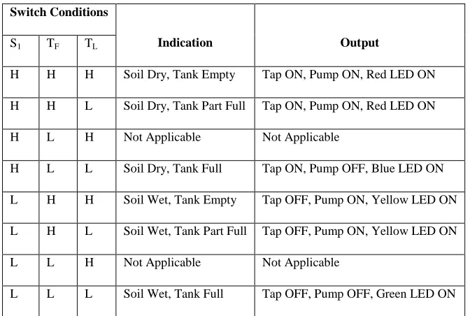
Light emitting diodes (LED) driven through transistors were used to indicate the valve and pump output signals. The conditions of the switches and the outputs observed from the microcontroller are given in table 1.
International Journal of Emerging Technology and Advanced Engineering
Website: www.ijetae.com (ISSN 2250-2459, ISO 9001:2008 Certified Journal, Volume 4, Issue 6, June 2014)
[image:7.612.139.475.157.383.2]658
TABLE 1
SENSOR CONDITIONS AND MICROCONTROLLER DECISIONS
Switch Conditions
Indication Output
S1 TF TL
H H H Soil Dry, Tank Empty Tap ON, Pump ON, Red LED ON
H H L Soil Dry, Tank Part Full Tap ON, Pump ON, Red LED ON
H L H Not Applicable Not Applicable
H L L Soil Dry, Tank Full Tap ON, Pump OFF, Blue LED ON
L H H Soil Wet, Tank Empty Tap OFF, Pump ON, Yellow LED ON
L H L Soil Wet, Tank Part Full Tap OFF, Pump ON, Yellow LED ON
L L H Not Applicable Not Applicable
L L L Soil Wet, Tank Full Tap OFF, Pump OFF, Green LED ON
International Journal of Emerging Technology and Advanced Engineering
Website: www.ijetae.com (ISSN 2250-2459, ISO 9001:2008 Certified Journal, Volume 4, Issue 6, June 2014)
[image:8.612.123.532.127.554.2]659
Figure 5: Flowchart of Program Executed by Microcontroller
Yes
No
Yes Yes
No No
Close Tap, Turn off pump, Turn ON Green LED Start
Open Tap, Turn ON pump, Turn ON Red LED
Close Tap, Turn ON pump, Turn ON Yellow LED Open Tap, Turn
OFF pump, Turn ON Blue LED
Monitor Soil Sensor Inputs
Initialize
Processor
Is Aerial Tank
dry?
Is Aerial Tank full ? Is soil
International Journal of Emerging Technology and Advanced Engineering
Website: www.ijetae.com (ISSN 2250-2459, ISO 9001:2008 Certified Journal, Volume 4, Issue 6, June 2014)
[image:9.612.83.529.110.373.2]660
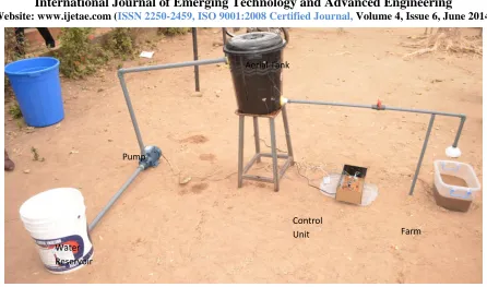
Figure 6: Realization of the Miniature Irrigation System
IV. CONCLUSION
A stand alone farm irrigation system has been designed and implemented using a microcontroller. Due to the few number of components used the system has a high degree of reliability. The size of the pump and tap used can be varied to meet the required expanse of a particular farm. The system can easily be deployed in remote farms as the amount of electrical power it consumes is small.
REFERENCES
[1] J. Dhiman, S. Singh, and S. Dhiman, “Utilization of Irrigation Water Using Microcontroller”, Automatic Control and Information Sciences, Vol.1, No. 1, pp.1-5, 2013.
[2] J.S. Awati and V.S. Patil, “Automatic Irrigation Control by Using Wireless Sensor Networks”, Journal of Exclusive Management Science, Vol. 1, Issue 6, pp. 1-7, June 2012.
[3] T. Boutraa, A. Akhkha, A. Alshuaibi and R. Atta, “Evaluation of the Effectiveness of an Automated Irrigation System Using Wheat Crops”, Agriculture and Biology Journal of North America, Vol. 2, No. 1, pp.80-88, 2011.
[4] M. Yildirim and M. Demirel, “An Automated Drip Irrigation System Based on Soil Electrical Conductivity”, The Philippine Agricultural Scientist, Vol. 94, No. 4, p.343-349, December, 2011.
[5] S. Singh, and N. Sharma, “Research Paper on Drip Irrigation Management Using Wireless Sensors”, International Journal of Computer Networks and Wireless Communications, Vol. 2, No. 4, pp.461-464, August 2012.
[6] A. Cellatoglu, and B. Karuppanan, “Remote Sensing and Control for Establishing and Maintaining Digital Irrigation”, International Journal of Advanced Information Technology, Vol. 2, No.1, pp.11-25, February 2012.
[7] R.G. Evans and W.M. Iversen, “Remote Sensing and Control of an Irrigation System Using a Distributed Wireless Sensor Network”, IEEE Transactions on Instrumentation and Measurement, Vol. 57, No. 7, pp.1379-1387, 2008.
[8] G. Yang, Y. Liu, L. Zhao, S. Cui, Q. Meng and H. Chen, “Automatic Irrigation System Based on Wireless Network”, International Conference on Control and Automation, ICCA, 2010, pp.2120-2125. [9] R.M. Faye, F. Mora-Camino, S. Sawadogo, and A. Niang, “PC-Based Automation of a Multi-Mode Control for an Irrigation System, International Symposium on Industrial Embedded Systems”, Lisbon, 4-6 July, 2007, pp.310-315.
[10] Y. Zhou, K. Yang, L. Wang, and Y. Ying, “A Wireless Design of Low-Cost Irrigation System Using ZigBee Technology”, International Conference on Networks, Security, Wireless Communications and Trusted Computing, 2009.
[11] Y. Kim and R.G. Evans, “Software Design for Wireless Sensor-Based Site-Specific Irrigation”, Computer and Electronics in Agriculture, Vol. 66, No.2, pp.159-165, 2009.
[12] F.S. Zazueta and J. Xin, “Soil Moisture Sensors”, Bulletin 292, Florida Cooperative Extension Service, Institute of Food an Agricultural Sciences, University of Florida, April, 1994.
[13] Microchip Technology Inc., PIC16F84A Data Sheet, http://ww1.microchip.com/downloads/en/DeviceDoc/35007b.pdf (Accessed 15/05/2013)
[14] M.A. Mazidi, R.D. McKinlay and D. Causey, PIC “Microcontroller and Embedded Systems: Using Assembly and C for PIC18”, Pearson Education Inc., Upper Saddle River, New Jersey, 2008.
[15] Microchip IDE,
http://www.microchip.com/microchip.www.SecureSoftwareList/ [16] Proteus VSM, Labcenter Electronics,
http://www.labcenter.com/Products/
Water Reservoir
Pump
Aerial Tank
Control