HP 98035A
Installation and Service
rli~
HEWLETT
Hewlett-Packard products are warranted against defects in materials and workmanship. For Hewlett-Packard Desktop Computer Division products sold in the U.S.A. and Canada, this warranty applies for ninety (90) days from date of delivery.* Hewlett-Packard will, at its option, repair or replace equipment which proves to be defective during the warranty period. This warranty includes labor, parts, and surface travel costs, if any. Equipment returned to Hewlett-Packard for repair must be shipped freight prepaid. Repairs necessitated by misuse of the equipment, or by hardware, software, or interfacing not provided by Hewlett-Packard are not covered by this warranty.
NO OTHER WARRANTY IS EXPRESSED OR IMPLIED, INCLUDING, BUT NOT LIMITED TO, THE IMPLIED WARRANTIES OF MERCHANTABILITY AND FITNESS FOR A PARTICULAR PURPOSE. HEWLETT-PACKARD SHALL NOT BE LIABLE FOR CONSEQUENTIAL DAMAGES.
Manual Part No. 98035-90000 Microfiche No. 98035-99000
Hewlett-Packard Desktop Computer Division 3404 East Harmony Road, Fort Collins, Colorado 80525
Chapter 1: General Information Introduction System Configurations General Specifications Power Requirements Temperature Range Accuracy Signal Lines Physical Description
Chapter 2: Installation
Introduction
Select Code
Device Cable
Identification
Cable Preparation
Field Installation of Option 100 Cable Changing the Data Code Format
Recommended Driver and Receiver Circuits
Peripheral Driver Circuits
Peripheral Receiver Circuits I/O Timing Considerations
Chapter 3: Operations
Simplified Theory of Operation
A Note About Syntax Real Time Information
Set Real Time
Request Real Time
Timing/ Counting Units Define Output
Define Input
Unit State Control Halt All Units
Activate All Units
Halt Selected Unit Activate Selected Unit
Output Operations: Interrupts
Input Operations: Counting Milliseconds '
Request Value,
Clear Value Status and Control
Request Error
Request Trigger
Request Unserviced Interrupt, '
Interface Communications, ,,' By-Pass Self Test,
Activate Clock Chip Test Point, "
Deactivate Clock Chip Test Point
Direct I/O ' , , " ""
Read External Input Lines Pulse External Output Lines
Chapter 4: Service
Calibration Procedures """"" Calibrating the 1 MHz Oscillator
Calibrating the 32.768 KHz Oscillator
General Troubleshooting Hints .
Repair and Troubleshooting of the Processor Board,
Handling Cautions,
Processor Replacement
98035A RAM Testing "
Battery Testing and Replacement, , ,
Interface Board Details "
Replaceable Parts List,
Component Locator
Circuit Diagram
Processor Board Details
Replaceable Parts List, ,
Component Locator
Circuit Diagram
Appendix
98035A Instruction Set
ASCII Character Codes
Sales and Service Offices
,38 38 39 ,40 40 42 43 45
" 46
47 47 ,48 ",,48 49 ,53 54 54 56 57 ,,57 ",,57 58 ,59 60
" 60 , 61
, 61
" ,62
62
",63 63
65
".,,66
" 67
Printing History
New editions of this manual will incorporate aU material updated since the previous edition.
The manual printing date and part number indicate its current edition. The printing date
changes when a new edition is printed. (Minor corrections and updates which are incorporated
at reprint do not cause the date to change.) The manual part number changes when extensive
technical changes are incorporated.
February 1981. .. Third Edition
NOTICE
The information contained in this document is subject to change without notice.
HEWLETT-PACKARD MAKES NO WARRANTY OF ANY KIND WITH REGARD TO THIS MATERIAL, INCLUDING, BUT NOT LIMITED TO, THE IMPLIED WARRANTIES OF MERCHANTIBILITY AND FITNESS FOR A PARTICU-LAR PURPOSE. Hewlett-Packard shall not be liable for errors contained herein or for incidental or consequential damages in connection with the furnishing, performance or use of this material.
Hewlett-Packard assumes no responsibility for the use or reliability of its software on equipment .that is not furnished by Hewlett-Packard.
Chapter
1
General Information
Introduction
The HP 98035A is a real time clock in a standard interface housing. The HP 98035A Real Time
Clock adds real time referencing and time related control to Hewlett-Packard's line of desktop computers.
Available to the computer is real time information containing the month, day, hour, minutes,
and seconds in the U.S. or European date format. The date format is jumper selectable. A
built-in rechargeable battery maintains back-up power for the Real Time Clock whenever the
computer is switched off.
Also available in the Real Time Clock is access to four independent timing/ counting units that
can be operated in either interrupting (output) or counting (input) modes.
Some of the operations are performed with little or no interaction with the computer after initial
setup.
[image:7.613.166.488.506.701.2].System Configurations
Option 001
u.s.
date format - real time output as month:day:hours:minutes:secondsOption 002
European date format - real time output as day:month:hours:minutes:seconds
Option 025
Operating note for the HP 9825 desktop computer
Option 031
Operating note for the HP 9831 desktop computer
Option 035
Programming techniques for the HP 9835 desktop computer
Option 045
Programming techniques for the HP 9845 desktop computer
Option 100
HP 98035A Real Time Clock with approximately 1.8 meters (6 feet) of unterminated cable for
I/O operations
Field-Installable Cable
A field-installable cable is available to convert the standard clock into an Option 100 type
rev: 2/81
General Specifications
Power Requirements
Supplied by Computer
+
5 volts at 300 rnA+
12 volts at 20 rnA-12 volts at 5 rnA
Internal Battery
2.5 volt rechargeable nickel-cadmium
Maximum recharge time: 16 hours
Minimum discharge time:
with clock chip outputs enabled: 10 hours (see pages 24, 41, and 47)
with clock chip outputs disabled: 2 months
Temperature Range
Operating: 5° C to 40° C
Storage: - 20° C to 55° C
Accuracy (ms counter/interrupt functions)
Initial Accuracy
Factory adjusted to ±s ppm at 25°C ambient after a one hour warmup.
Frequency Temperature Characteristic
Maximum drift of ±S ppm from a 25°C reference over the range from 10°C to 40°C.
Accuracy (time-of-day functions)
Initial Accuracy
Typically within ±30 ppm at 25°C.
Frequency Temperature Characteristic
Maximum drift of
+
10 ppm, -30 ppm from a 27°C reference over the range from 10°C to40°C.
Crystal Aging
Maximum drift of 5 ppm in the first year; less than 3 ppm in subsequent years.
Signal Lines!
Four data input lines, 11-14. The inputs are low-power Schottky with internal pull-up resistors.
The low level current is 2mA, and the logic sense is negative true (Low = "I" = True).
Four data output lines, 01-04. The outputs are open-collector types with a low-level drive
capability of 8mA. The logic sense is negative true (Low = "1" = True).
There is also a synchronizing output that can be used in I/O operations. It provides a 4
microsecond wide pulse every millisecond and is an open-collector output.
For more information on interfacing external devices to the HP 98035A and the associated
timing requirements, see Chapter 2, figures 2-5, 2-6, and 2-7.
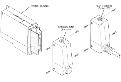
Physical Description
The 98035A Real Time Clock is contained in a plastic housing, approximately 163 x 91 x 35
mm (6.4 x 3.6 x 1.4 in.). Figure 1-2 illustrates the clock housing. The front housing which plugs into the calculator contains the clock, nicad battery, interface, and associated control circuitry
on two printed circuit boards. One of the boards has a 24-pin connector for the optional
interface cable.
REAR HOUSING ~
(Standard)
/~
/Figure 1-2: 98035A Housing
~,,--REAR HOUSING
(Option 1 00) ~
! /'
~/ [image:10.612.86.498.390.670.2]Chapter
2
Installation
Introduction
The standard 98035A Real Time Clock as shipped from the factory has no liD cable.
Installa-tion consists of plugging the unit into one of the liD slots on the back of the computer, letting
the battery charge, and then setting the time. The Option 100 clock has an unterminated liD
cable, and thus requires you to install the necessary terminating connector for your application.
The standard Real Time Clock can be reconfigured to an Option 100 type device by the
addition of an liD cable, HP part number 98035-61600.
Information concerning the operation of the 98035A Real Time Clock should be read and understood before attempting to install this peripheral (refer to Chapter 3).
If an external device is to be interfaced to an Option 100 clock, a thorough understanding of the
Select Code
All peripheral devices and interfaces attached to an HP desktop computer have a unique
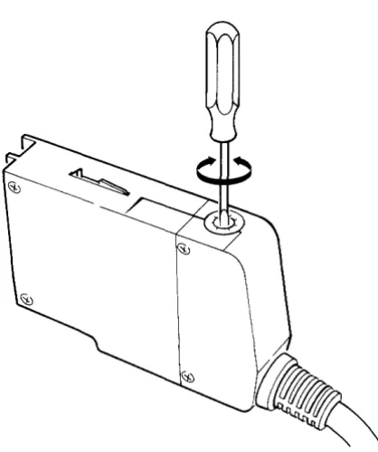
address that allows them to be individually selected. These addresses are called select codes and can be set by the user. The 98035A Real Time Clock is preset at the factory to select code
9. If it is necessary to change the setting, rotate the select code switch on the top of the rear housing to the desired position, using a small screwdriver as illustrated in Figure 2-1.
NOTE
Two interfaces or peripherals should not be set to the same
[image:12.615.185.394.320.569.2]select code.
Peripherals internal to the computer such as built-in tape drives and printers have their own
select codes. Care should be taken so that the 98035A's select code differs from those of the
internal devices. For a listing of the internal peripheral select codes, please refer to your
computer's operating manual.
NOTE!
Select codes 0 through 7 are on the low priority interrupt level and select codes 8 through 15 are on the high priority level. Devices requiring fast interrupt service should be set to
the high level. Priority within a level is in order of the select
code, with 7 and 15 having the highest priority. The Real Time Clock should be given a high priority number if it is to be used in the interrupt mode.
Device Cable
2Identification
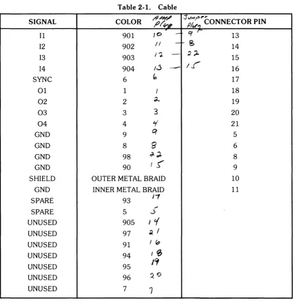
The 24 lines of the device cable are used for signals as shown in Table 2-1. Any input lines
(11-14) to the 98035A Real Time Clock that are not used should be grounded. All other unused
[image:14.613.78.515.211.654.2]lines may be left unterminated.
Table 2-1. Cable
SIGNAL COLOR /9/?1'~ ~r¥-"I :J (Jf~" ""r'I"CONNECTOR PIN
~
at
r-11 901 10
-
1312 902 /1
-
f-S
1413 903 I"').
-
~;l. 1514 904 /.j
-
If'
16SYNC 6
b
1701 1 I 18
02 2 d..- 19
03 3 3 20
04 4
¥
21GND 9
q
5GND 8
6'
6GND 98 d-;l. 8
GND 90
t!,
9SHIELD OUTER METAL BRAID 10
GND INNER METAL BRAID 11
SPARE 93
J,
~
SPARE 5 ..J
UNUSED 905 J t{
UNUSED 97 ~ I
UNUSED 91 I "
UNUSED 94 I~
UNUSED 95
ICf
UNUSED 96
QO
UNUSED 7
7
11 = Input port 1
12 = Input port 2
13 = Input port 3
14 = Input port 4
NOTE
01 = Output port 1
02 = Output port 2
03
=
Output port 304
=
Output port 4Wire color codes shown correspond to the standard resistor color code. Digits have the
follow-ing significance:
x
X X
Most prevalent Calor!
1
\Narrow bandWidest band
0- Black 5 - Green
1 - Brown 6 - Blue
2 - Red 7 - Violet
3 - Orange 8 - Gray
4-Yellow 9 - White
NOTE
The outer shield (and drain wire) should not be connected to
anything on the external device end.
Cable Preparation
Tools needed:
Safety razorblade or knife
Diagonal clippers
Wire strippers
Soldering iron, solder
Heatshrink tubing or tape
Cable
Procedure:
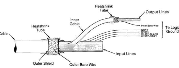
Heatshrink
Tube Output Lines
Inner Bare Wire
1
T L .GRAY 0 ogle
~
~~~~~ WHITE WHITE-BLACK Ground WHITE-GRAY [image:16.615.126.468.100.231.2]Outer Bare Wire
Figure 2-2. Cable Preparation
Refer to Figure 2-2.
1. Cut the cable to the required length, allowing some length for slack.
2. Using the razorblade or knife, strip off about 10 cm (4 inches) of the outer plastic jacket.
3. Cut off the outer shield and outer bare wire even with the outer plastic jacket, taking care
not to nick or otherwise damage the inner wires.
4. Cover the end of the jacket and outer shield with heatshrink tubing or tape.
5. Strip and connect the cable wires as required by your peripheral.
6. Be sure to connect the logic ground wires (refer to Table 2-1) to the peripheral's logic ground.
7. Isolate unused wires with heatshrink tubing or tape.
CAUTION
TO PREVENT POSSIBLE DAMAGE TO THE 9803SA REAL
TIME CLOCK, THE CABLE'S LOGIC GROUND WIRES
MUST BE CONNECTED TO THE EXTERNAL
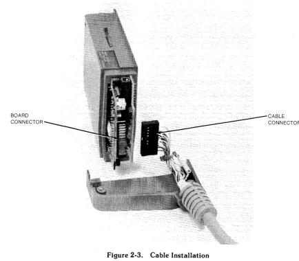
Field Installation of Option 100 Cable
The standard 98035A Real Time Clock can be fitted with an I/O cable, HP part number
98035-61600. This will convert it to an Option 100 device.
Tools required:
# 1 pozidrive screwdriver
BOARD CONNECTOR
Procedure:
[image:17.613.92.526.252.632.2]Refer to Figure 2-3.
Figure 2-3. Cable Installation
1. Remove the six screws on the rear housing of the Real Time Clock.
CABLE CONNECTOR
CAUTION
THE REAL TIME CLOCK CONTAINS A RECHARGEABLE
BATTERY THAT MAINTAINS POWER TO PARTS OF THE
CLOCK AT ALL TIMES. WHEN ANY PART OF THE CASE IS REMOVED, DO NOT SHORT ANY OF THE TRACES OR
COMPONENTS WITH A METALLIC OBJECT OR
DAM-AGE MAY RESULT.
NOTE
Errors in the real time may result if there is finger contact with the Real Time Clock circuit boards while any part of the
case is removed.
3. Remove the connector supplied with the standard Real Time Clock from the rear of the
processor board (refer to Figure 2-3). Install the new cable connector in place of the old
connector. Note that the cable connector can be installed in one direction only.
4. Make sure that the groove in the cable strain-relief engages in the edge of the cable
feed-through hole on the rear housing, and reassemble the clock case.
Changing the Date Code Format
Option 001 clocks are supplied properly formatted for the U.S. style, and Option 002 clocks are
supplied properly formatted for the European style. If you change your mind or have the wrong
option, you can select the format of your clock by moving a jumper.
European format:
Day: Month:Hours:Minutes:Seconds
U.S. format:
Month:Day:Hours:Minutes:Seconds
The date code format is selected via a jumper on the 98035-66501 printed circuit board inside
the 98035A Real Time Clock. Refer to Figure 2-4.
[image:19.615.182.457.382.568.2]EUROPEAN POSITION
Figure 2-4. Date Code Format Jumper
Tools required:
Needle nose pliers
# 1 pozidrive screwdriver
Low-power soldering iron
Procedure:
1. With the clock removed from the computer, remove the four screws that hold the rear
housing in place and remove it. On Option 100 devices, unplug the external cable.
2. Remove the four screws that hold the front housing together, two on each side. Remove
the front housing pieces, exposing the two printed circuit boards. Be aware of the latch
arm at the top of the housing.
CAUTION
THE REAL TIME CLOCK CONTAINS A RECHARGEABLE
BATTERY THAT MAINTAINS POWER TO PARTS OF THE
CLOCK AT ALL TIMES. WHEN ANY PART OF THE CASE
IS REMOVED, DO NOT SHORT ANY OF THE TRACES OR COMPONENTS WITH A METALLIC OBJECT OR
DAM-AGE MAY RESULT.
NOTE
Errors in the real time may result if there is finger contact with the Real Time Clock circuit boards while any part of the
case is removed.
3. The jumper can be moved with the board assembly intact or separated. If you choose to
separate the two boards, do so gently. Do not bend any connecting pins or disturb the
position of any components.
4. The Date Code jumper is located on the upper right-hand side of the board containing
the select code switch (refer to Figure 2-4).
5. Using a pair of needle-nose pliers and a low-power soldering iron, grasp the jumper wire
and carefully unsolder it.
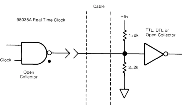
Recommended Driver and Receiver Circuits
3To prevent possible damage to the 98035A Real Time Clock and external devices, it is
recom-mended that you employ the following interface circuits.
Peripheral Driver Circuits
Each of the input lines on the 98035A Real Time Clock is connected to a low-power Schottky
gate. A resistive divider is connected to each of the input lines (refer to Figure 2-5) to hold the
input line voltage at +3.4 volts when the cable is disconnected. The input voltage to the input
lines must not exceed +5.5 volts.
Input Drive Requirements
VI Maximum Input Voltage
VIH High Level Input
Voltage (min)
VIL Low Level Input
Voltage (max)
ilL Low Level Input
Current (max)
98035A Real Time Clock
Cable
+5v
Clock
-5.5 Volts
2.0 Volts
0.8 Volts
-2.0 rnA
Peripheral
TTL or OTL
[image:21.612.157.488.290.691.2]+5v
Figure 2-5. Recommended Peripheral Driver Circuits
Peripheral Receiver Circuits
Each output line from the 98035A Real Time Clock is driven by an open-collector circuit. The
current sinking capability of each driver is 8 rnA and the breakdown voltage is
+
15 volts. Donot apply a negative voltage to the output lines.
Output Drive Capability
VOH High level Output
Voltage (max) 15 Volts
VOL Low Level Output 0.4 Volts @ 4 rnA
Voltage (max) 0.5 Volts @ 8 rnA
IOL Low Level Output
Current (max) 8.0mA
Since each driver has an open-collector output, the external peripheral receiving circuit must
have a pull-up to a positive voltage (not to exceed
+
15V), and must be restricted to sourcingless than 8mA. The recommended receiving circuit is shown in Figure 2-6.
98035A Real Time Clock
Open Co!lector
Cable
+5v
[image:22.617.127.445.455.639.2]TTL, DTL or Open Collector
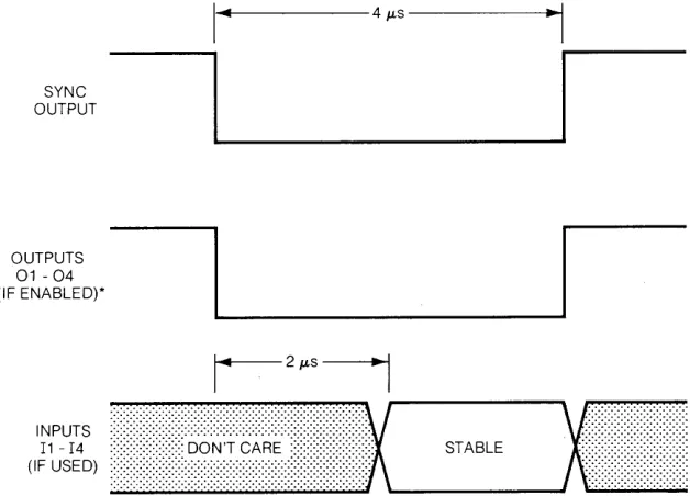
I/O Timing Considerations
The 98035A Real Time Clock has an additional output that is provided to synchronize the
peripheral inputs with internal clock timing. The SYNC line will output a 4 microsecond wide
pulse every millisecond. Refer to Figure 2- 7.
The Real Time Clock inputs data from the external lines 3 microseconds after the falling edge of
the SYNC pulse. The data on these lines must be stable at least 2 microseconds after the falling
edge of the SYNC pulse. Input signals may appear asynchronously. Refer to Figure 2.7
SYNC OUTPUT
OUTPUTS
01 - 04
(IF ENABLED)*
' ... 1 - - - 4 JLS
---1~~,
~I_~I
r-
2JLSi
---,.
:.:.:.:.:.:.:.:.:.:::::::::::::::::::::::::::::::::::::::::::::::::::::::::::::: ::::::::::::::::::::::::::::::::
···x
x···
(I'i~~::)
••••••••••••••••••••••••~%~:~
••
~~~.~
•••••••••••••••• :: •••••• ; ,-__
S_T_AB_L_E _ _ ..J'\ \ i
[image:23.612.167.481.263.489.2]*OUTPUT LINES WHICH ARE NOT ENABLED REMAIN AT HIGH LEVEL
Chapter
3
Operations
This chapter defines the instructions and operations of the HP 98035A Real Time Clock. It
presents a general overview without referencing any specific model of computer. For pro-gramming examples with a specific desktop computer, refer to the operating note supplied with
your option of the Real Time Clock.
NOTE
Information exchanges between the 98035A and the
com-puter cannot be handled using DMA transfers and should not
be handled using interrupt transfers. Data can be input and
output using standard handshake transfers. Specific
exam-ples of recommended I/O instructions can be found in the
appropriate operating note.
Simplified Theory of Operation
A functional block diagram of the 98035A Real Time Clock is shown in Figure 3-1. The Real
Time Clock has six major functional groups: a clock circuit with rechargeable batteries,
con-trol circuitry, four timing/ counting units, four input ports, four output ports, and an optional
(Option 100) external cable.
The clock circuit is crystal controlled and power is maintained by a rechargeable battery. The
clock is contained on a single LSP chip, and its purpose is to maintain the real time while the
desktop computer is switched off. This clock has a resolution of 1 second.
The control circuit decodes and executes all the instructions sent to the Real Time Clock by the
desktop computer. When power is applied or a system reset is executed on the desktop
com-puter, the control circuit performs a test of the Real Time Clock unit and then reads the real
time from the clock chip. From this point on the control circuit alone maintains and updates the
real time every millisecond.
There are four timing/ counting units which are software controlled. These units can be
con-figured to any input or output port. When set to the output mode, a timing/ counting unit will
interrupt2 the computer when selected real time specifications are met. If the Real Time Clock is
equipped with the Option 100 I/O cable, a 4JLs pulse will also be output on the selected line at
this time. In the input mode, the Real Time Clock increments the timing/ counting units once
every millisecond. Option 100 Real Time Clocks increment a timing/ counting unit once every
millisecond when the input line is enabled.
The input ports act as buffers between the timing / counting units and external drivers. These
buffers are scanned once every millisecond by the control circuit. The appropriate counter will be incremented each time the scanner sees a logic "true" input. Standard Real Time Clocks
have all input ports connected so that a "true" signal is always present; hence the counters are
incremented every millisecond. Option 100 clocks have an external cable connected to the
ports so that you can input your own signals. Recommended driver circuits are shown in Chapter 2, Figure 2-5, and the input timing diagram is shown in Figure 2-7.
The output ports act as buffers between the timing / counting units and external receivers.
Option 100 Real Time Clocks have an external cable connected to the ports so that the output signals can be used externally. No connection is made to the output pins on the standard
clocks.
The Option 100 cable allows the Real Time Clock to monitor and trigger external devices. The
cable is 1. 8 metres (6 feet) long, and is unterminated on one end. Standard Real Time Clocks
can be retrofitted with this cable, HP part number 98035-61600. For information on installing
the cable, refer to Chapter 2.
Both the standard and Option 100 Real Time Clocks use the same instruction set.
TP
TO COMPUTER :-:.:-:-:-:-:-:- INTERFACE
1/0 SLOT ... CIRCUITS
TP
CLOCK CHIP
NI-CAD BATTERY
...
CONTROL CIRCUITS
ANY UNIT MAY SELECT ANY FREE PORT
*
DEFAULT ASSIGNMENT02
03
04
11
12
13
14
OPTION 100
A Note About Syntax
Syntax is the way in which elements are arranged and connected to form an orderly combina-tion. In the case of the 98035A Real Time Clock, the elements are the standard ASCII codes
representing the following characters.
• the uppercase letters A through Z
• the numbers 0 through 9
• the characters / LF (line feed)
All other characters are ignored by the Real Time Clock. This makes it convenient to use
lowercase letters for comments in the clock's instructions. A listing of ASCII characters is
contained in the Appendix.
The following general conventions will be used in this manual to described the way in which
these elements may be combined to create instructions.
A - Color is used to represent actual characters which must be sent as
shown.
number - When a label is used, it represents a set of characters from which the
desired parameter may be chosen. A description of the set and its limits
will be given in the text following the syntax listing.
[ ] - Items in square brackets are optional. The instruction will be valid
whether or not these items are included. However, including an optional
item will generally change the exact meaning of the instruction.
LF - The label "LF" is used to represent a data delimiter. For the Real Time Clock, this can be either an ASCII decimal 10 (LF) or an ASCII decimal 47 (/).
The syntax statements in this manual show only the characters which are sent to the 98035A.
The computer statements used to send those characters are not shown. It is very important
that you keep this distinction in mind. For example, assume that you wanted to send a "U2H" to the clock. On the 9825, this could be done with the statement !'; ; ... ' ':::i:, ;;: :;::::' I··i ;;. On the
9835, this could be done with the statement C!l .... fr ' .. --': , . :::~; !i LJ ::::' 1"'4 ;; , or the statement l.'·.i I::;::' ::r.: 'T 1:::=
There are many desktop computers, and they all have a variety of output statements to chose
from. If you want further information on specific computer statements, refer first to your Real
Time Clock Operating Note or Programming Techniques manual. If you need even more
Real Time Information
The 98035A Real Time Clock has two operations for real time. These are "Set Real Time" for
setting or changing the real time, and "Request Real Time" for reading the real time. The
98035A uses a 24 hour time format in which the day begins at 00 hours and ends at 23 hours,
59 minutes and 59 seconds.
Set Real Time
Syntax:
S time LF
This instruction is used to set or change the current time maintained in the Real Time Clock.
This is accomplished by sending an "S" followed by the new real time and a delimiter (/ or
LF). The real time is formatted in one of two ways.
Option 001, or US date format:
Month Day Hours Minutes Seconds
Option 002, or European date format:
Day Month Hours Minutes Seconds
The data field for each time group (month, day, hour, ... ) mU$tbe two digits wide. If the number
is less than ten, i.e. 0-9, that number must be preceeded by a zero. For example: 1 becomes
01,0 becomes 00, and 9 becomes 09. This means that the variables used in the write statement
must either be string types or be formatted so that leading zeros will not be removed. The Real
Time Clock will allow any number of lower case comment characters to appear within the
string, as long as none of these characters correspond to instructions used by the Real Time
Clock (A-Z, /, or =). For example, if the real time to be set is June 18, 12:01:00, this string
could be output to the Real Time Clock:
"Set real time; month 06, day 18, hours 12, minutes 01, seconds 00 / "
If only part of the real time needs to be changed, only that time group and the groups to the
right need to be specified in the string. For example, if the real time was 07: 13: 16: 58: 17, and
the minutes should actually be 59, the following could be output to the Real Time Clock:
"S59: 17" LF
If there is not an even number of digits in the time data, or if the leading zeros are deleted, an
Upon receiving the delimiter terminating the string, the Real Time Clock will add 10
mil-liseconds to compensate for computer processing time, and then update the clock circuit and
the registers containing the real time.
NOTE
The updating of the clock circuit which maintains the real
time when the power is removed from computer can take up
to 90 seconds, depending on the current real time and the desired real time. During this interval, do not remove power
or RESET the computer, otherwise the real time will be lost
and the clock circuit may be left in a high power state. This
will cause the batteries to discharge in less than 24 hours.
The Real Time Clock tests each time group (month, day, hour, ... ) for validity. The real time has
the following limits:
Minutes and Seconds: 00 - 59
Hours: 00 - 23
Days: 01-31 for January, March, May, July, August, October, December
01-30 for April, June, September, November
01-29 for February
Months: 01-12
An error will be generated in the Real Time Clock (see' 'Request Error") and the time set will
not be executed if the limits of any of these groups is exceeded. For example, if you attempted
to set the time as
"04(april): 31 (days): 12: 00: 00
the Real Time Clock would generate an error and abort the instruction since April has only 30
days.
When only part of the date is to be changed, (day in U.S. format and month in European
format), the Real Time Clock uses the current unchanged part of the date to test the validity of
attempted to change the real time to "day, 31, hours, 12, minutes, 00, seconds, 00", the Real
Time Clock would abort the instruction since June has only 30 days.
Request Real Time
Syntax:
R
When an ASCII "R" is sent to the Real Time Clock by the desktop computer, the Real Time
Clock will output the current real time in one of the following formats.
Option 001, or US date format:
Month: Day: Hours: Min utes: Seconds
Option 002, or European date format:
Day: Month: Hours: Minutes: Seconds
Each time group (Month, Day, Hour, ... ) is two digits wide and is separated by a colon (:). The
first digit sent from the Real Time Clock is the beginning of the month group (Option 001) or
the day group (Option 002), and the last byte is a LF (ASCII decimal 10).
The Real Time Clock immediately stores the current real time in a buffer upon reception of the
"R" instruction. This data remains in the output register indefinitely until it is read by the
desktop computer or overwritten by the execution of another instruction in the Real Time Clock.
The entire real time can be input to the desktop computer by using a string variable
dimen-sioned to 14 characters or by using five variables. The colons (:) will terminate the computer
data input when using non-string variables, so the real time may be input to the desktop
computer in five separate read operations. The transfer of the real time will be terminated any time another instruction is sent to the Real Time Clock. For example, consider the following
sequence:
Output to Real Time Clock: Input to the desktop computer:
"R" LF
read operation, store into A
read operation, store into B
read operation, store into C
The result of this sequence (assuming the Real Time Clock has the US date format) would be the month value stored in A, the day in B, hours in C, minutes in D, and seconds in E. If the
programmer inserted a write operation to the Real Time Clock which output another instruction
between the' 'read operation, store into B" , and the' 'read operation, store into C" , all the real
time data that would have been input to C, D, and E would be lost.
If the Real Time Clock has lost the real time due to hardware problems, or the current real time
is found to be in error, it will output to the computer
88: 88: 88: 88: 88 LF
in response to a real time request. An error will also be generated within the Real Time Clock
(see "Request Error").
The Real Time Clock does not automatically identify leap years, therefore February always has
28 days. You can change the date to February 29 using the Set Real Time instruction without
generating an error.
Timing/Counting Units
The 98035A Real Time Clock contains four timing/ counting units. These units reside in
read/write memory within the Real Time Clock and are controlled using program instructions.
A timing/ counting unit can be in one of three modes. Figure 3-1 may help you visualize these
alternatives. When in the counting (input) mode, a unit is assigned (connected) to one of the
input ports. When in the interrupt (output) mode, a unit is connected to one of the output ports.
The third possibility is that the unit is not connected to any port. In this mode, a unit is referred
to as "unassigned".
When a timing/ counting unit is in the counting (input) mode, the register is used to count milliseconds. The input lines (Il-I4) of the Option 100 cable can be used to control this
counting. The numeric value in the register can range from zero to 9 999 999 999. More
information on this mode of operation can be found in the "Input Operations" section.
When a timing/ counting unit is in the interrupt (output) mode, real time information stored in
the register can cause the Real Time Clock to interrupt the computer at a preset time and/ or
output a pulse on an output line (Ol-04) of the Option 100 cable. More information on this
Define Output
Syntax:
U number
=
[0 number]This instruction defines (assigns) a specified timing unit to a specified output port for the
purpose of interrupting the computer or pulsing an output line (Option 100).
The parameter "number" must be the integer 1, 2, 3, or 4. Any other integer causes the
instruction to abort and an error is set in the Real Time Clock (see "Request Error"). Any
character that is not a number is ignored. If a multi-digit number is sent, only the first digit is
recognized; all extra digits are ignored. For example, if "- 39.7" were sent as the parameter
"number", the Real Time Clock would use the value "3". The minus sign is ignored because it
is not a number and the "9.7" is ignored because the "3" satisfied the parameter
require-ments.
The Define Output instruction must be executed before the Set Match, Set Delay and Set
Period instructions can be used. (These instructions are described later in the chapter.)
NOTE
When the Real Time Clock is initialized by a power-on, a
system reset, or the "B" instruction, unit 1 is automatically
assigned to output port 1. To make output port 1 available
to other units, send the instruction "Ul
="
LF.Any number of lower case comment characters can be inserted into this instruction. For
exam-ple, the Real Time Clock will interpret these two instruction sequences the same way:
"U 1
=
0 1" or "Unit 1 is set=
to Output 1"A timing/counting unit must be in the halt state (see section on "Unit State Control") before it
can be defined to an output port.
The most recent Define Output instruction overrides any previous Define Output instruction
involving the same timing/ counting unit. For example:
"Unit 1
=
Output port 3"•
•
•
Unit 1 is assigned to output port 3 in the first part of the program, and later on is reassigned to
output port 4. At that time, unit 1 is no longer assigned to output port 3.
Only one timing/ counting unit per output port is allowed. If the following program sequence
was sent to the Real Time Clock, an error would be generated.
"Unit 1
=
Output port 3" "Unit 2 = Output port 3"The first instruction line causes output port 3 to be assigned to unit 1. The second instruction
line attempts to assign unit 2 to output 3, which has already been assigned to unit 1. This causes
an error to be generated within the Real Time Clock, and the second instruction sequence will
not be executed. In order to assign output port 3 to unit 2 in the previous example, output port
3 must first be "freed" or undefined. In general, this is accomplished by sending to the Real
Time Clock:
U number
=
The previous example can then be changed so that it will work.
Define Input
Syntax:
U number
=
[I number]"Unit 1
=
Output port 3""Unit 1 = "
"Unit 2 = Output port 3"
This instruction defines (assigns) a specified timing unit to a specified input port for the purpose
of counting milliseconds.
The parameter "number" must be the integer 1, 2, 3, or 4. Any other integer causes the
instruction to abort and an error is set in the Real Time Clock (see "Request Error"). Any
character that is not a number is ignored. If a multi-digit number is sent, only the first digit is recognized; all extra digits are ignored. For example, if "-39.7" were sent as the parameter
"number", the Real Time Clock would use the value "3". The minus sign is ignored because it
is not a number and the "9.7" is ignored because the "3" satisfied the parameter
require-ments.
The Define Input instruction must be executed before the Request Value and Clear Value
NOTE
When the Real Time Clock is initialized by a power-on, a
system reset, or the "3" instruction, unit 2 is automatically
assigned to input port 1. To make input port 1 available to
other units, send the instruction "U2
="
LF.Any number of lower case comment characters can be inserted in this instruction. For example
the Real Time Clock will interpret these two instruction sequences the same way:
"Ul
=
11"or
"Unit 1 is set
=
to Input I"The most recent Define Input instruction overrides any previous Define Input instruction
in-volving the same timing/ counting unit. For example:
"Unit 1
=
Input port 3"•
•
•
•
"Unit 1
=
Input port 4"Unit 1 is assigned to input port 3 in the first part of the program, and later on is reassigned to input port 4. At that time, unit 1 is no longer assigned to input port 3.
Only one timing/ counting unit per input port is allowed. If the following program sequence
was sent to the Real Time Clock, an error would be generated.
"Unit 1
=
Input port 3""Unit 2
=
Input port 3"The first instruction line causes input port 3 to be assigned to unit 1. The second instruction line
attempts to assign unit 2 to input port 3, which has already been assigned to unit 1. This causes
an error to be generated within the Real Time Clock, and the second instruction sequence will
not be executed. In order to assign input port 3 to unit 2 in the previous example, input port 3
must first be "freed" or undefined. In general, this is accomplished by sending to the Real Time
Clock:
The previous example can then be changed so that it will work.
"Unit 1 = Input port 3" "Unit 1 = "
"Unit 2
=
Input port 3"A timing / counting unit must be in the halt state (see section on "Unit State Control") before it can be assigned to an input port.
If the Real Time Clock is an Option 1 00 device, the counters will be incremented each mil-lisecond that an input is true on the appropriate line. On the standard Real Time Clock, the
counting units will be incremented once per millisecond, thus making them millisecond timers.
The Option 100 Real Time Clock units can be configured to perform as millisecond timers by connecting the desired input line to ground.
Unit State Control
A timing/counting unit can be in one of two states: Active (on) or Halt (off).
A timing/ counting unit must be in the halt state before it can be reconfigured, (reassigning input and output ports), or before any time specifications are changed (real time, real time
match, delay or period). A unit can be selectively placed in the halt state using the Halt Selected
Unit instruction, or all units can be simutaneously halted using the Halt All Units instruction.
The Set Match instruction will halt the active unit when the match specifications are met and the interrupt and/ or output pulse is sent out. This also applies to the Set Match accompanied by a
Set Delay instruction.
A unit can be individually activated using the Activate Selected Unit instruction. All the
tim-ing/ counting units can be Simultaneously activated using the Activate All Units instruction.
The timing/ counting units must be placed in the active state before they can provide the
Halt All Units
Syntax:
A
The Halt All Units instruction places all the timing/ counting units in halt state. This instruction
can be executed at any point in the program, and will not affect any of the input/ output port
assignments, counter values, match, delay, or period specifications.
Any number of lower case comment characters may appear in this instruction. For example:
"All units halt" LF
will perform the same function as the single capital "A". This instruction may be executed with
units already in the halt state or with unassigned units without generating an error in the Real
Time Clock.
NOTE
The "Halt All Units" instruction clears the Interrupt Enable
Flag in the Real Time Clock. The Real Time Clock must be
re-enabled for interrupts if they are to be serviced upon re-activation of the timing/ counting units.
Activate All Units
Syntax:
F
The "Activate All Units" instruction simultaneously activates all the timing/ counting units.
This instruction may be executed at any point in the program without affecting any of the input/ output port assignments, counter values, or changing the value of the match, delay, or
period specifications.
Any number of lower case comment characters may appear in this instruction. For example:
"Fire all units" LF
The "Activate All Units" instruction may be executed with units already in the active state, or
with unassigned units without generating an error in the Real Time Clock.
Caution must be used when employing the Activate All Units instruction in a program as this
instruction affects the operation of the Delay and Periodic instructions. The start of the Delay or
Periodic interval occurs when the unit is either activated, or if used with the match instruction,
when the real time match occurs. If an Activate All Units instruction is executed while a unit is
active and processing a delay or periodic interval, the delay or periodic interval will be re-timed from the point of execution of the Activate All Units instruction.
Halt Selected Unit
Syntax:
U number H
This instruction causes the specified timing/ counting unit to enter the halt state. The specified
unit must be assigned to an input or output port before this halt instruction can be executed.
The parameter "number" must be the integer 1, 2, 3, or 4. See the "Define Output" section for
a detailed explanation.
Any number of comment characters may appear in the instruction sequence. For example, unit
1 is placed in the halt state by the following sequence:
"Unit 1 is Halted" LF
Activate Selected Unit
Syntax:
U number G
This instruction causes the specified timing/ counting unit to enter the active state. The specified unit must be assigned to an input or output port before this activate instruction can be
executed.
The parameter "number" must be the integer 1,2,3, or 4. See the "Define Output" section for
a detailed explanation.
Any number of comment characters may appear in the instruction sequence. For example, unit
3 is placed in the active state by the following sequence:
Output Operations: Interrupts
When one or more timing/ counting units are in the output mode, the Real Time Clock can interrupt the computer, providing the computer in use is interruptable and the Real Time Clock
is enabled for interrupts. These interrupts may be set for a specific time using the Set Match
instruction. Other output instructions include Set Delay and Set Period. These instructions may be executed by themselves or in various combinations.
Set Match
Syntax:
U number M [time] LF
The Match instruction causes the Real Time Clock to interrupt the computer and/ or output a pulse (Option 100) at a specified time.
The parameter "number" must be the integer 1, 2, 3, or 4. See the "Define Output" section for
a detailed explanation.
The format for the' 'time" parameter is3 :
Day Hours Minutes Seconds
The data field for each time group (day, hours, minutes, ... ) must be two digits wide. If the
number in the data field is less than ten, i.e. 0-9, that number must be preceeded by a zero. For
example: 1 becomes 01, 0 becomes 00, 9 becomes 09. This format must be followed,
other-wise an error will be generated (see "Request Error"), and the match specification will not be
entered.
The Match instruction does not have the capablity to match at a preset month, although no
error will be generated if a month group is entered.
It is not necessary to enter all eight digits of the match time, just the required time group and those groups to the right. As an example, unit 2 could be set to match daily at 11:30 AM to give
a lunch break warning. The output sequence to the Real Time Clock could be:
U2M 11 30 00 LF
Any number of lower case comment characters may appear in the output sequence. The above
example can be re-written as follows:
"Unit 2 will Match at 11:30:00 for lunch break" LF
The match specifications are cleared by writing:
Unumber MLF
The match time has a resolution of one second. The control section compares the match time to
the real time when the real time is incremented, and begins the interrupt request and/ or output
pulse whenever the real time and match time correspond.
NOTE
The match time specifications must be entered and the unit
activated (see "Unit State Control") at least one second
be-fore the real time becomes equal to the set match time.
In order to enter or change any of the match specifications, the appropriate unit must be in the
halt state (see "Unit State Control") and assigned to an output port.
After the specifications have been entered the unit must be placed in the active state (see "Unit State Control") before the unit can match. After the Real Time Clock has matched and
exe-cuted the interrupt and/ or output pulse, that unit is placed in the halt state. In order to get that
unit to match again, it must be returned to the active state.
In general, the following sequence of instructions would be used to set the match time:
A
U number
=
0 numberU number M time LF
U number G
Halt all units
Define to output
Set match
Activate selected unit
The Real Time Clock does not use the month in the comparison with the real time, but does use
it in the testing of the match time for validity. If no month is given, then the current month is used in the testing of the day limits. The limits on the Set Match instruction are the same as those used in the Set Real Time instruction.
If for example, the current month in the real time is April, the Real Time Clock would not accept
the following instruction:
"Unit 3 is to Match at day: 31, hours: 12, minutes: 30; seconds: 00" LF
The Real Time Clock will test the day group against the limits for April, which is 1 to 30, will
The above example can be modified so that it works by adding the month group:
"Unit 3 is to Match at month: 05, day: 31, hours: 12,
minutes: 30, seconds: 00." LF
Note that the month is used only to test the validity of the day group.
Set Delay
Syntax:
U number D [delay] LF
The Set Delay instruction causes the Real Time Clock to wait a specified time before
interrupt-ing the computer and/ or outputtinterrupt-ing a pulse (Option 100). The delay may be specified to occur
after a real time match or after a unit activation.
The parameter "number" must be the integer 1, 2, 3, or 4. See the "Define Output" section.for
a detailed explanation.
The parameter "delay" is an integer number up to 8 digits long that sets the delay time in
milliseconds. This gives a delay range of one millisecond to 99 999 999 milliseconds or 27.78
hours.
Delay Time
d milliseconds
secon s
= - - - - -
mmu es . t = milliseconds h ours = milliseconds1000 60 000 3 600 000
The delay specification can be cleared by writing to the Real Time Clock:
U number D LF or U number DO LF
Note that to enter or clear the delay instruction and specifications, the unit must be assigned to
an output port and be in the halt state (see "Unit State Control").
The Set Delay instruction may be used by itself to provide a single interrupt after a set interval
regardless of the real time. When used by itself the delay begins immediately after the unit is
activated (see "Unit State Control"). The following sequence of instructions could be used if a
delay is to be executed by itself:
A
U number
=
0 numberU number D delay LF
U number G
Halt all units Assign to output
Set delay time
In general, the following sequence of instructions would be used to set a match time and enter a
delay specification:
A
U number
=
0 numberU number M time LF
U number D delay LF
U number G
Set Period
Syntax:
U number P [interval] LF
Halt all units
Define to output port
Set match
Set delay
Activate selected unit.
The Set Period instruction causes the Real Time Clock to interrupt the computer and/ or
output a pulse (Option
100)
at a specified interval. This instruction can be executedim-mediately, after a Match, after a Delay, or after a Match with Delay, and it will continue until the
specified unit is halted.
The parameter "number" must be the integer 1, 2, 3, or 4. See the "Define Output" section for
a detailed, explanation.
The parameter' 'interval" is an integer number up to 8 digits in length that sets the duration in
milliseconds between interrupts and/ or output pulses. This gives a range of one millisecond to
99 999 999 milliseconds or 27.78 hours.
d milliseconds
secon s =
-1000
Interval Time
. t milliseconds
mm u es = --=-:..:.:...;:....:...:....:-.:...:..:.:..
60 000
hmilliseconds
ours =
-3 600 000
The interval specification can be cleared by writing to the Real Time Clock:
U number P LF or U number PO LF
Note that to enter or clear the period instruction and interval specifications, the unit must be
assigned to an output port, and be in the halt state (see "Unit State Control").
When the Set Period instruction is used by itself, the interrupts and/ or output pulses begin
In general, the following sequence of instructions would be used to set the periodic interval and
execute it without a match.
A
U number
=
0 numberU number P interval LF
U number G
Halt all units
Assign unit to output port
Set periodic interval Activate selected unit
The Real Time Clock begins executing the Set Period instruction immediately after the Activate
Unit instruction is received.
Any number of lower case comment characters can be used in the Set Period instruction. For
example, the previous sequence of instructions can be executed as a single line with comment
characters. In this example, unit one and output port four are used with a periodic interval of
12345 milliseconds.
"halt All units. Unit 1 is set
seconds / Unit 1 Go" LF
to Output 4. Unit 1 has a Periodic interval of 12.345
If the Set Period instruction is used with a real time match, the interrupt and/ or output pulses
begin at the match time. If a delay instruction is also used, these interrupts and/ or output
pulses begin after the match time plus delay.
The general sequence of instructions to the Real Time Clock would be as follows:
Match with Periodic:
A
U number
=
0 numberU number M time LF
U number P interval LF
U number G
Delay with Periodic:
A
U number
=
0 numberU number D delay LF U number P interval LF
U number G
Halt all units
Define unit to output port
Set match
Set period
Activate selected unit
Halt all units
Assign unit to output port
Set delay
Set period
Activate selected unit
Input Operations: Counting Milliseconds
When one or more timing/ counting units are in the input mode, the Real Time Clock can
measure the time of computer operations and external events (Options 100) with millisecond
accuracy. Timing units are assigned with the Define Input instruction and monitored with the
Request Value instruction. Control over the timing units is provided by the "Unit State Con-trol" instructions, the Clear Value instruction, and the external input lines (Option 100).
Request Value
Syntax:
U number V
The Request Value instruction causes the Real Time Clock to output the current counter value
of the specified timing/ counting unit. This value can then be input to the computer with a standard read or enter operation. The value returned is a ten digit number indicating the
number of milliseconds that the unit was active.
The parameter "number" must be the integer 1, 2, 3, or 4. See the "Define Input" section for a detailed explanation.
The specified unit must be assigned to an input port before the Request Value instruction can
be executed. The Request Value instruction may be performed on a unit in either the active or
halt state (see "Unit State Control") and any number of comment characters may be inserted.
If the computer executes a read operation to the Real Time Clock without first requesting a
counter value, the Real Time Clock will output a LF in response, without generating an error.
The standard Real Time Clocks are wired so that the counting units increment every
mil-lisecond. This means that the counting units may be used as millisecond timers. As an example,
the Real Time Clock can be used as a stop watch to time a benchmark program. In the following example unit 2 and input port 1 are used because they are configured that way at power-up.
"Unit 2 Go" LF
Benchmark routine on computer
"Unit 2 Value request" LF
Read operation
The result of this program will be a display of the time that the benchmark routine took in
milliseconds. The range of this operation is one to 9 999 999 999 milliseconds or 115.7 days.
Note that the Option 100 timing/ counting units do not act as millisecond timers unless they are
externally enabled. They can be enabled by connecting the input line low (to ground) for the
desired input port. Table 2-1 lists the input lines and their respective colors.
Information on interfacing to the Option 100 Real Time Clock is contained in Chapter 2.
Clear Value
Syntax:
Unumber C
The Clear Value instruction resets the specified timing/ counting unit to zero. The specified unit
must be assigned to an input port before the Clear Value instruction can be executed. How-ever, the unit may be in either the active or halt state. Any number of comment characters may
be inserted in the instruction.
The parameter "number" must be the integer 1, 2, 3, or 4. See the "Define Input" section for a
Status and Control
The Real Time Clock is both an intelligent peripheral device and an interface. The peripheral
device portion maintains three registers which provide useful information about errors and
interrupts. The interface portion is similar to a 98032A, which means that it has several registers
used for communication with the computer. This section of the manual explains the function of
these various registers and how they may be accessed.
Also in this section is a more detailed explanation of the initialization process in the Real Time
Clock and the means used to control it.
Request Error
Syntax:
E
The Real Time Clock performs self tests on its control hardware whenever power is applied or
when the controlling computer is reset. The Real Time Clock also tests instructions and data
that are transferred to it by the computer. If hardware problems are found or if illegal instruc-tion sequences are detected, bits are set within an error register. This error register is eight bits
wide, with the lower four bits dedicated to software errors and the upper four bits reserved for
hardware errors. The software errors are cleared each time the register is read by the computer.
NOTE
The error code should be input to the computer using a
binary input operation.
Standard read operations use ASCII codes for data transfer. The error code read in this manner
may not be recognizable. For example, the error code could be a binary 00111000, which in
decimal is 56. A binary read of this error code will result in "56", but a standard read operation will result in an "8", which is the ASCII character corresponding to a code of 56.
The following is an explanation of the error codes.
Least Significant Bit
7 6 5 4 3 2 1 0
BAD
R/W BITS R/W BITS CLOCK REAL INSTRUCTION UNIT INSTRUCTION
MISSED
4-7 0-3 HARDWARE TIME UNEXECUT ABLE DEFINITION or INTERRUPT
DEFECTIVE DEFECTIVE DEFECTIVE LOST NOW MISMATCH DATA OUT
OF RANGE
Bit 0: Is 1 when an interrupt has been missed. This could happen when two or more
tim-ing/ counting units request interrupts at intervals to narrow to be serviced by the
computer. This would also happen if a second interrupt occurred and the interface
was not re-enabled for interrupts after the first occurrence. To determine which interrupting unit was missed, see "Request Unserviced Interrupt" .
Bit 1: Is 1 when incorrect instructions or out-of-range data are sent to the Real Time Clock. It
is set by incorrect usage of instructions, or when entered data (real time, match
time, ... ) is invalid.
Bit 2: Is 1 when the instruction sent to the clock is inconsistent with the current assignment of
units and ports. Some examples are: sending an interrupt instruction to a unit which
is assigned to an input port, attempting to assign two units to the same port, or
requesting the value of an unassigned unit.
Bit 3: Is 1 when attempting to execute a Set Real Time instruction when there is unit defined
to an output port in the active state. This is also caused by trying to change the match, delay, or periodic specifications on an active unit, or by trying to reassign an
active unit.
Bit 4: Is 1 when the real time maintained by the clock circuitry is lost. This generally occurs
when the voltage of the ni-cad battery drops below a certain level. The battery can
lose its charge if the storage temperature limits have been exceeded, if the Real
Time Clock has not been used enough to allow the battery to recharge, or if the
computer was turned off in the first 10 seconds after power-on (or a reset). This can
leave the clock circuitry in a high power state, draining the battery. The clock circuit
can take up to 90 seconds to perform a time set. During this period the removal of
power or a computer reset will cause the real time to be lost and this error to be
generated. The Real Time Clock outputs "88:88:88:88:88" in response to a real
time request when this error is detected.
Bit 5: Is 1 when the clock hardware is found defective.
Bit 6: Is 1 when the block of read/write memory containing bits 0-3 is found defective.
Request Trigger
Syntax:
T
Whenever a timing/ counting unit generates an interrupt and/ or outputs a pulse on the Option
100 cable, a register in the Real Time Clock remembers which output port triggered that action.
This "trigger" code can be read at the beginning of the interrupt service routine to determine
which timing/ counting unit-output port pair requested the interrupt.
The trigger code should be input to the computer using a binary input operation. A detailed
discussion of the reason is contained in the previous section on "Request Error".
The trigger word is structured in the following manner:
Least Significant Bit
7
1
6 J 5 I 4 3 2 1 aALWAYS ZERO OUTPUT OUTPUT OUTPUT OUTPUT
PORT 4 PORT 3 PORT 2 PORT 1
Bit 0: Is 1 when the timing/ counting unit that is assigned to output port 1 has triggered.
Bit 1: Is 1 when the timing/ counting unit that is assigned to output port 2 has triggered.
Bit 2: Is 1 when the timing/ counting unit that is assigned to output port 3 has triggered.
Bit 3: Is 1 when the timing/ counting unit that is assigned to output port 4 has triggered.
Bit 4: Is always O.
BitS: Is always O.
Bit 6: Is always O.
Bit 7: Is always O.
The trigger code register is cleared immediately after a Request Trigger instruction. If there has
been more than one interrupt request since the last time the trigger code was read, only the
most recent request will be retained in the trigger code register. The trigger code register will
contain multiple interrupt requests only when the multiple requests occur simulateously.
Whenever the trigger code is requested, the code is stored in an output buffer in the Real Time
Clock. This buffer holds the trigger code until the next read operation by the computer clears it,