E L E C T R I C
EDUC..ATIO~.A.L
. F : : F t O J E C T S
P r o j e o t : An.a.log COIT"lputer
EF.140
Copyright General Electric Co. 1961
HOW TO USE THIS EOOK
To make it easier to build your analog computer and use it for solving mathematical problems, this book is divided into the following six parts:
PAR T 1 - What You Will Do with This Kit
PART 2 - How to Unpack Your Kit
PA RT 3 - How to Assemble Your Computer
PA RT 4 - How Your Computer Works
PAR T 5 - Putting Your Computer to Work
PAR T 6 - Suggestions for Further Reading
PART 1
WHAT YOU WILL DO WITH THIS KIT
Men have been using devices and machines of various kinds to help them with arithmeti-cal arithmeti-calculations for thousands of years. The ancient Romans and ancient Chinese had the abacus, a wooden frame with rows of sliding beads. Experts can do many problems with astonishing speed on the abacus. Mechanical adding machines have been used in offices for decades.
Now, we have a new Age of Computers -electronic computers. In these, electrons do the counting and computing with the speed of lightning. Electronic computers were invented less than two decades ago. Already the tasks they perform are almost too numerous to count. Scientists use them for working out their theories and in the design, launching and tracking of satellites. Airplanes are tested without ever leaving the ground on simulated flights worked out on computers. Tomor-row's supersonic airliners will be completely dependent on computer-controlled automatic pilots; to prevent weak points that might blow out, supersonic transports probably won't have any windows. Giant computers are busy in business and industry, too. They run auto-matic refineries for oil companies, keep books for banks, help the Census Bureau count U.S. noses, keep inventory for giant manufactur-ing companies, help utilities keep track of customers' bills, assist the government in making sure everyone pays his proper taxes. There are even computers that can play chess and other games, and computers are being designed to obey instructions of the human voice and to translate languages.
In 1955, there were less than 100 giant
electronic computers at work in the United States, and most were used by mathematicians and physicists for complicated theOretical calculations. By 1960, there were more than 10,000 and their number was still on the way up.
There art two types of computers - digital and analog.
A digital computer counts, like a man counting on his fingers. It adds, subtracts, divides and multiplies by counting. However, the "fingers" it counts are pulses of elec-tricity. It counts these so fast - a million or more pulses a second in some computers -that it can solve in minutes problems -that would take a man days to work out.
Analog computers, on the other hand, work by comparing physical quantities. For instance, in the computer you will build and in all analog computers built today, numbers are multiplied by multiplying electric cur-rents. Just how this works you will see later.
Analog computers are not nearly as accu-rate as digital machines. But there are some kinds of work, such as plotting the path of a satellite or missile, that they do more effi-ciently than a digital computer.
Like other simple analog computers, the one you are about to build gives approximate answers, accurate to two places. However, it was not designed to give exact answers to problems, but to introduce you to the prin-ciples of computers and to a new and fascinat-ing field of science and technology- the design and use of computers. With the kit and manual, you will also learn how scientists and engineers work with numbers.
PART 2
HOW TO UNPACK YOUR KIT
Your Work Area
You will find assembly of the kit easier if
you choose a flat surface, such as a table, in a good light as your work area.
What You Will Need
should buy four new D-sized batteries. These are standard flashlight batteries.
Opening the Kit
Hold onto both the clear plastic top and the black plastic bottom of the box. You will need them as part of the cabinet for your computer. When you removed the top of the box, you found two transparent "skin packs" contain-ing components for your kit. One of the packs
is screwed to the bottom of the box. Three mounting boards as well as three scale cards are also in the bottom of the box.
Work the screwdriver out of the larger skin pack as in Fig. No. 1. Remove the three long screws holding the smaller skin pack to the bottom of the box. Lay the two skin packs flat on your work table and identify the compon-ents by comparing them with Fig. No.2.
REMOVING SCREWDRIVER
-FIGS. NO. 1 and 2
KNOW YOUR COMPONENTS
Here is some information about the princi-pal components in the skin packs and in the bottom of your kit:
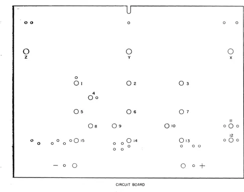
1. Mounting Boards. Three are supplied. The
small one with the white upper surface and the rough underside is the circuit board on which you will mount the electronic com-ponents at the heart of your computer. The numbered and lettered holes are for the mounting of components and connectors. The large mounting board labelled "PROJECT: ANALOG COMPUTER" will hold the three computer dials and the scale plates. The third, with a rectangular hole in the center and the words "TONE" and "CALIBRATE" beneath round holes on either side, will support the on-off switch, tone control and calibration control.
2. Scale Plates. These three cards contain the scales you will use in solving problems with your computer. As you will see, changing scales to solve a particular problem is easy. On the reverse side of each scale is a Memory Board, containing formulas and other infor-mation on how to solve a great variety of problems.
3. Potentiometers. You have five potentiome-ters altogether. Potentiomepotentiome-ters are also called "pots" or variable resistors. They contain thin wire or a piece of carbon that offers resistance to the flow of electric current. The amount of resistance can be varied by turning the shaft of the potentiometer. Three of your pots will be fitted with scale knobs and are for the computer dials. They will have a key part in carrying out multiplication and other mathe-matical operations electrically; exactly how they do this will be explained later. The other two pots will be used in the tone and calibra-tion controls.
4. Transistors. The mighty midgets that have revolutionized electronics. Transistors are hardly bigger than aspirin tablets, but they can do nearly anthing done by vacuum tubes and they do many things better. They are being used for pocket radios, hearing aids small enough to fit into eyeglass frames, giant computers, control systems for rockets and missiles, transmitters for space satellites. Three transistors will be used in your com-puter to generate a tone in an earphone. You will use this tone as a guide in finding the
correct answers to problems.
5. Capacitors. Electronic filters with the re-markable property. of blocking direct current and passing alternating current. Capacitors help transisto:r~operate efficiently. ., ; , 6. Resistors. ,'You have just read aboutpoten-tiometers or variable .resistors. Your kit also includes "fixed" resistors' whose resistance cannot be changed. Fixed resistors help pro-tect important components against currents that might damage them, and will also help your computer to operate efficiently.
7. Earphone. For hearing the tone that will help you find the correct answer on the answer dial.
8. Tone Control. To adjust the earphone tone to a, pleasant pitch.
9. Calibration Control. To adjust the com-puter so that it can give correct answers. 10. On-off Switch. To turn your computer on and off.
11. Hairpin-and-Spring Connectors. For con-necting wires without soldering or twisting them together.
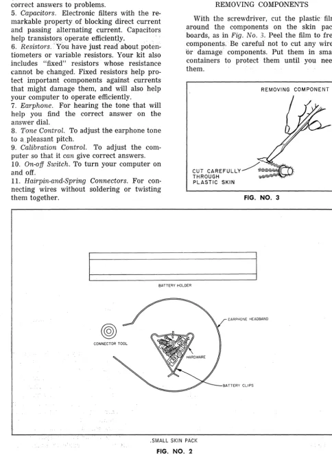
REMOVING COMPONENTS
With the screwdriver, cut the plastic film around the components on the skin pack boards, as in Fig. No.3. Peel the film to free components: .. Be careful not to cut any wires or damage components. Put them in small containers to protect them until you need them.
REMOVING COMPONENT
FIG. NO.3
BATTERY HOLDER
EARPHONE HEADBAND
.". . .'~ .
.SMALL SKIN PA'CI<
[image:4.620.59.544.63.725.2]TONE KNOB
CAPACITORS
TRANSISTORS
POTENTIOMETER
WIRE
POTENTIOMETER
"W" BRACKETS
SMA~L
~R
BRACKET"Z"BRACKETS
POTENTIOMETER POTENTIOMETER
SCREWDRIVER
LARGE CENTER BRACKET
SCALE KNOBS
"ZOO BRACKETS
POTENTIOMETER
OFF-ON SWITCH
CALIBRATION KNOB
FIXED RESISTORS
o
PART 3
HOW TO ASSEMBLE YOUR COMPUTER
Now -that you are familiar with your tools aDd materials, take a look at the illustration
on
Page 2 to see the general arrangementYour computer will have when finished. We're
readyto
build a computer.Step 1.
Place the circuit board in front of you with the white surface up and the U-sp'1.ped notch away from you, as in Fig. No. 4:<
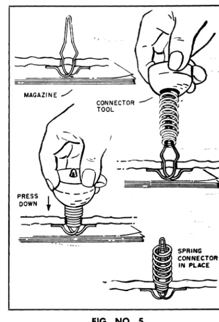
Install hairpin-and-spring connectors in
holes number [1] through [15]. Here's one
easy way to do it. Push the loop of the hairpins up through the bottom of the board, as in
Fig_ No.5. Now place the board onaftat sur-face, such as a table top. Put amagi'fzfrnrunder
0 0
o
z
0
01
4
00
05
OS
09
0 a
0015
0 o 0 a a
a a
-
a0
o
o
y02
06
014
athe board so that the table won't be scratched. Using the connector tool as in the illustration, and with the small end of the spring down, ram the spring firmly over the pin until it clicks into place. You may have to wiggle it a bit to make it stay upright.
Step 2.
Mount battery clips and holder, being espe-cially careful to match the positive and nega-tive clips with the plus and minus signs on the board. You can identify each clip by its distinctive shape. The positive clip has a dotted pattern on one end. The negative clip is unmarked. (See Fig. No.6.) Mount the clips and battery holder simultaneously. Clips fit
o o
o
x03
07
II
010
000
12
013
a0
aa a 0
0
a+
CIRCUIT BOARD
[image:6.618.49.536.322.704.2]into the trough of the holder. A screw goes down through each clip, the battery holder, then the board. Put a flat speednut on to hold each screw. Be sure to put the nut on so that its corners can bite into the board. Tighten only enough to hold the battery holder and clips firmly. Batteries and connecting wires
will be added later.
Step 3.
Inspect the five potentiometers furnished with your kit. Pick out the two marked 300 and the one marked 10K. Leave the two smaller pots, marked 200 and 200K respeG-tively, aside for the moment. You will need them later.
The three pots with numbers are for three computer dials. The numbers refer to their resistance values: 300 means 300 ohms, and 10K means 10,000 ohms. (Resistance to the flow of electricity is measured in a unit called the ohm.)
Insert a 300-ohm pot through hole [Xl from the upper surface of the board, as in Fig. No. 7. Point the three terminal prongs away from you. Secure the pot in this position with one of the five large nuts furnished in the kit. Tighten the nut so that the pot is held securely and will not turn when the dial knobs
/ NEGATIVE
/ CLIP
o
!
RED WIRE
o
DOTTED PATTERN
~'"
YELLOW CONCAVE WIRE SIDE UP
FIG. NO.6
PRESS
DOWN
FIG. NO.5
SPRING CONNECTOR
IN PLACE
are attached. Use a pair of pliers if necessary. In the same way, install the 10K pot in hole lYl and the other 300-ohm pot in hole [ZJ.
~~300OHU
POTI
ItUT
SIDE FACE UP
[image:7.623.324.545.56.380.2] [image:7.623.58.549.428.728.2]WIRE DESCRIPTION
FROM VIA
NO. LENGTH COLOR HOLES TO
1 7% BLACK TER.lofZ
-
TER; 10fY2-
...-7%..
) TER. L of·y-
TER~ 101*~ IP,4
..
CONN.4 ". G·M·I TER. 3 of Tc;:::-
4 6 RED TER. 2 ofT - TER. 2 of SW5 7 " BATTERY - S-R TER. 1 of SW R6
r'~
6 73,4 " TER.3'of.Y - TER_ 20fX7 9 1/2 " ~ONN. L F'Q'P TER.20iSW R7
.A 10 BROWN TER. 2 of Y C-H CONN. 11
-..9.- 141/2
..
TER.ZQfl A·J CONN. 12 ,.. -~lU'~'~- - 131/4 ORANGE CONN: 13 N-U-W TER. 20fB~H---' 12% BLUE T:ER.3'OfZ B·Y-X TER. 3 of B
\12 /171/2
..
lERcS..ofX E·T-U TER. 1 of B~ 5 1/2 YELLOW BATTERY
+
-0· CONN. 14",~r4"~ 9% " rot ~. ..I..-.Of-,l\ -D- BATTERY
+
lJ&
2 BARE CONN. 7-
CONN. 3~ ~-'21/2 " CONN. 6
-
CONN. 10,-i7 3 1/4
..
CONN. 14-
CONN. 15l§/
6V4..
CONN. 1 CONN. 2 CONN. 3PART NO. DESCRIPTION
R-I, R-5 1.5K 1/2 W. RESISTOR
<b
R-2 200K POT.
R-3 10K 1/2 W. RESISTOR
A)
R-4 22K 1/2 W. RESISTOR
~
R-6, R-7 33 1f2 W. RESISTOR-~-. R-B 200 CARBON POT.
R-9, R-11 300 W.W. POT.
R-10 10K W.W. POT.
C-I, C-2 .05 M.F.D.
TR 1-2-3 GREEN CODE
EP-I lK EARPHONE
SW-l ON OFF SWITCH
~
~
RI CI~
~-
~
~
;-0
~
-H-- -H-- -H-- -H-- -H-- 0
RESISTOR CAPACITOR BARE WIRE WIRE HOlE~
WIRE UNDER ABOVE SPRING BOAR ".
TRANSISTOR
= t = - - - - -
Jy
-=-..::::-..::::-- -- - ----=-
-=-
-==
==
==.-=-
-=-- -=-- -=-- -=-- -=-- -=--
~xRI ~
II
FIG. NO.8
A
c
[image:9.621.10.543.51.723.2]Step 4.
The three pots you have just installed are the basic working parts of your computer. But numerous other components and a consider-able amount of wiring, both on the circuit board and in other parts of your computer, are needed for the computer to function properly.
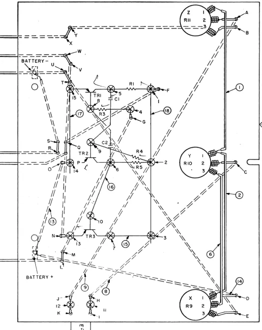
Let's install the circuit board wiring. First, study the wiring diagram in Fig. NO.8. Instructions for installing wiring and com-pOMhl;s ate in the text below. However, you will find'i it helpful to look at the diagram and see where things go. The diagram also contains handy tables listing all wire connec-tions and components. It's a good idea to check your work against the tables as you go along, to make sure you have made the right connections and installed the right compo-nents in the right places.
All wires are ready to use, cut to needed length and with ends stripped of insulation. Different colors are used for easy identifica-tion. "
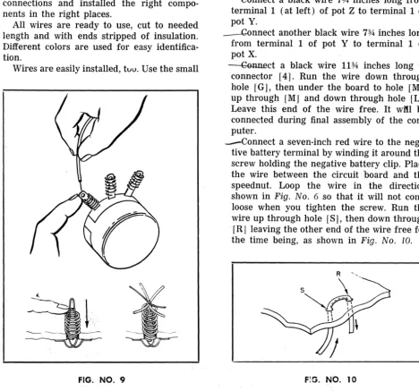
Wires are easily installed, tllU. Use the small
FIG. NO.9
black spring to connect a wire to a potentio-meter or switch terminal. Slip the spring over the terminal and push it down far enough to expose the small hole at the end of the ter-minal, as in Fig. No.9. Slip the end of the wire through the hole. It will be held tightly when you release the spring.
To insert a wire iIi . a hairpin-and-spring connector, push down the spring and slip the end of the wire through the hairpin loop as in the illustration. Release the spring and the wire will be locked in place. If a wire must be removed, simply push down the spring and pull the wire out. If thick and thin wires'
must"
be inserted in the same connector, put the thin wire over the thick one to assure good contact.Reil<i
y'
to '~i~e the circuit board? Let's go. --eonnect a black wire 7% inches long from terminal 1 (at left) of pot Z to terminal 1 of pot Y.--Gannect another black wire 7% inches long from terminal 1 of pot Y to terminal 1 of pot X.
~ct a black wire 11% inches long to connector [4]. Run the wire down through hole [G], then under the board to hole [M],
up through [M] and down through hole [L]. Leave this end of the wire free. It wit! be connected during final assembly of the com-puter.
-Connect a seven-inch red wire to the nega· tive battery terminal by winding it around the screw holding the negative battery clip. Place the wire between the circuit board and the speednut. Loop the wire in the direction shown in Fig. No.6 so that it will not come loose when you tighten the screw. Run the wire up through hole [S], then down through [R] leaving the other end of the wire free for the time being, as shown in Fig. No. 10.
[image:10.620.74.543.293.730.2]---~nf·terminal 3 (at the right) of pot Y to terminal 2 (at center) of pot X with a 7%-inch red wire.
'"""--fused the end of a 9V2-inch red wire in connector [1]. Pass it down through hole [F], up through hole [Q], and down again through hole [Pl. Leave the end disconnected.
* t1sing a brown wire 10 inches long, connect terminal 2 of pot Y and connector [11]. Pass the wire down and up through holes [C} and [HI.
--etmJ,1ect a 14V2 inch brown wire from termi-nal 2 of pot Z to connector [12]. Run it down through [Aland up through [J
I.
CeHlII~t a 13l;4-inch orange wire to connec-tor
r
13] . Run the wire down through hole [N], up through hole [V], and back under the board through hole [W]. Leave the end disconnected.r ConneCr1il2%-inch blue wire to terminal 3 of pot Z. Run it down through [B], up through
[YI and down through [X]. Leave the end disconnected.
- Connect a 171;2-inch blue wire to terminal 3 of pot X. Run the wire down through hole [EJ, up through [T] and down through [U
1.
Leave the end free.'I'wrrwires--aTe"llowconnected to the positive battery terminal screw, in the same way that you previously connected a wire to the nega-tive battery terminal. One, a 5V2-inch yellow wire, comes up through hole [0] and is
~nserted in c~nnector [~The other, a 9%-mch yellow WIre, goes from the battery termi-nal up through hole [D] to termitermi-nal 1 of pot X. Be sure to tighten the battery terminal screw holding the two wires.
Join connectors 13] amt [7] with a two-inch bare wire; [6] and [10] with a 211z-two-inch
piece of bare wire; and [14] and [15] \vith a 3l;4-inch piece of bare wire.
.-Run
a
"6'lA-inch piece of bare wire from con-nector [1] through concon-nector [2] to connec-tor [3].Step 5.
Weare now ready to install two of the transistors. Together with other electronic components, the two transistors will generate an electric current that oscillates or surges back and forth many times a second. After being amplified, that is made stronger, by a third transistor, this oscillating current will be used to generate a tone in the earphone to guide you in adjusting the answer dial
of
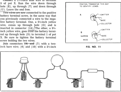
the computer.Before proceeding, study the leads on your transistors carefully. They'll look as in Fig. No. 11. (It makes no difference which form of transistor you receive in the kit. The two are electrically identical.)
POSITION TRANSISTOR THIS WAY TO I DENTI FY LEADS.
A
B
NARROW
WIDE
~
EMITTERBASE
,---COLLECTOR
FIG. NO. 11
[image:11.618.63.536.343.704.2]Note carefully which wire on each transistor is the base, which the collector and which the emitter. Be sure to attach each to the proper connector. Getting it wrong can damage the transistor as well as prevent your computer from working. Also use special care in bend-ing the ends of the transistor leads when you connect them. Avoid bending them back and forth. Fig. No. 12 shows how the leads of "" transistors and other components should be
bent.
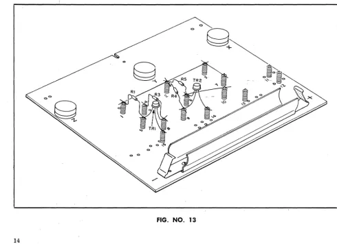
" CSfmeet UIt! first transistor, TR-1, as fol-lows: base to connector [8]; collector to connector [5]; and emitter to connector [15], as in Fig. No. 13. .
..., Connect another transistor, TR-2, in this way: base to connector [9]; collector to con-nector [6]; and emitter to concon-nector [14]. (See Fig. No. 13.)
Step 6.
Now install the resistors that will work with the two transistors. Your kit includes six fixed resistors'.' You will need four now. You can pick out the right ones by the three color
bands at one end of each resistor. There
-is
a standard color code by which the value of a resistor can be tol~t a glance: you can find the code in &-radio book if you should like to know more about it. Here are the resistors you now need and the color bands by which you can identify them:R-1: 1,500 ohms; brown-green-red"-color bands in that order from the end.
R-3: 10,000 ohms; brown-black-orange. R-4: 22,000 ohms; red-red-orange. R-5: 1,500 ohms; brown-green-red.
Connect resistors as in Fig. No. 13. R-1 to connectors [1] and [5]; R-a--to-[4] and [8'T:
~and R-5 to [2] and [6].
Step 7.
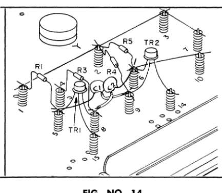
Two capacitors are installed next.., The. twp furnished in the kit are identical. One is
inserted in connectors [5] and [9] (C-1 in Fig. No. 14). The other, C-2, is connected to [8] and [6]. Before installing the capacitors, notice that two of the capacitor leads will cross. To avoid a short circuit, slip a piece of plastic insulating "spaghetti" over each of
[image:12.617.60.551.394.750.2]FIG. NO. 14
these wires before they are inserted in the connectors. Two pieces of plastic spaghetti are provided in the kit for this purpose.
~8.
The oscillating current generated by the first two transistors is amplified by the third, TR-3. After checking carefully to make sure you have identified the leads correctly, install
it as in Fig. No. 15: base to connector [10];
collector to [7]; and emitter to
[l!3l.
·FIG. NO. 16
FIG. NO. 15
~
Weare nearly ready to begin coupling the circuit board to the other mounting boards_ But first, install the on-off switch in the board marked "TONE" and "CALIBRATE." Insert the switch up through the rectangular hole in the center of the board from the unfinished underside of the board, so that the switch protrudes above the board. (See Fig. No. 16.) Secure with two screws and small flat speed-nuts. Insert the screws from the top of the board .
..-step 10.
Eight brackets are provided in the kit for joining the mounting poards and installing them in the finished computer. Four are shaped somewhat like the letter Z and will be called Z brackets. (See Fig. No. 17.)
Two other brackets, with five bends and four holes each, look something like elongated W's. These will be referred to as W brackets. Of the two remaining brackets, one is small,
the other one, much longer. They will be
referred to as the small center bracket and the large center bracket.
You will also find seven. U-nuts. These are small pieces of metal folded in a U shape, with a round hole on one side and a split hole on the other. This type of nut does not need to be held while a screw is inserted into it_ U-nuts are handy for attaching hardware in places where you . could not hold a nut with your fingers.
[image:13.621.64.281.55.243.2] [image:13.621.60.281.424.712.2]FOUR "z" BRACKETS TWO "w" BRACKETS
LARGE CENTER BRACKET ~
SMALL CENTER BRACKET
FIG. NO. 17
FiJ. No. 17. Make sure the hole in the nut coin-cides with the hole in the bracket. Notice that the two end flanges of the Z brackets are not equal in length. The U-nuts go on the short ends. Put a U-nut on the short end of each W bracket, as in the illustration, and also on the short end of the large center bracket. In all cases, the split side of the nut should be toward the main part of the bracket rather than away from it.
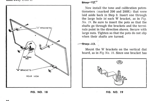
REAR VIEW
FIG. NO. 18
Mount a pair of Z brackets on the back of the vertical board that will support the com-puter dials, as in Fig. No. 18. Use the ends that do not have U-nuts. TheU-nut ends of
the brackets should point toward the upper edge of the board. Insert screws from the front of the board. Secure them with speednuts.
Now install the tone and calibration poten-tiometers (marked 200 and 200K) that were laid aside back in Step 3. Insert one through the large hole in' each W bracket, as in Fig. No. 19. Be sure to insert the pots so that the shafts go through the brackets and the termi-nals point in the direction shown. Secure with large nuts. Tighten so that the pots do not slip when their shafts are turned.
Step-;l3.
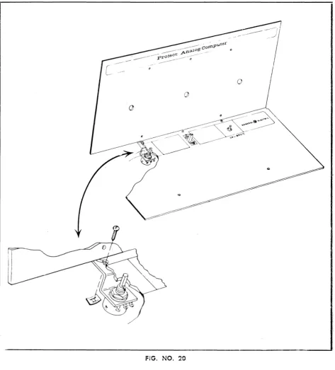
Mount the W brackets on the vertical dial board, as in'Fig No. 18. Since one bracket has
[image:14.618.58.554.35.770.2] [image:14.618.76.552.51.293.2] [image:14.618.61.557.396.739.2]the calibrate pot (200), and the other the tone control pot (200K), be sure to get each bracket and pot where it belongs (see dia-gram). Be sure also that the shafts of the pots point up, and that you attach the brackets to the board through the correct holes in the brackets. Secure with screws and speednuts. Now attach the board with the on-off switch. This will be the horizontal control panel of the computer and it will rest on the W brackets. Set the horizontal control panel on the W
brackets so that the shafts of the pots on the brackets come up through the large holes in the horizontal board, as in Fig. No. 20. Notice now a small hole immediately above the large holes in the horizontal board. These corres-pond to holes in the W brackets. Line up the small holes in the horizontal board with the holes in the brackets. Insert screws down through the horizontal board and the brackets. Secure with speednuts on the underside
of-the brackets. (See illustration.)
[image:15.613.62.535.211.734.2]•
___
-:r:i---step·14.
Mount the large center bracket to the two boards you have just joined. Holes in one end of the bracket will match holes near the switch on the horizontal and vertical boards, as in
Fig. No. 21. Be sure the bracket points perpen-ducularly away from the horizontal board.
-Step ts.
Next step is joining the circuit board to the horizontal and dial boards.
Mount the small center bracket on the rough side of the circuit board, as in Fig. No .
21. The bracket goes on the rough side of the circuit board at the U-shaped slot at the upper edge of the board, as shown in the drawing detail. Make sure that the free end of the bracket points upward as the circuit board stands up. Fasten with a screw and speednut. Now place the circuit board in position behind the dial board, so that the shafts of the three pots protrude through the three holes in the vertical board. Push the three large dial knobs on to the potentiometer shafts.
At this point the board is held in place only by the dial knobs. It must be attached more securely by means of the three brackets
PUSH DIAL KNOBS ONTO POT SHAFTS
[image:16.613.54.550.252.736.2]that just fit between the circuit board and the vertical dial board. As indicated in Fig. No. 21, these are the small center bracket you just mounted on the circuit board, and the rear bends of the W brackets. (Do not attempt to use Z brackets on the vertical dial board for attaching the circuit board. They do not fit onto the circuit board.) Fasten the uncon-nected end of the small center bracket to the dial board with a screw and speednut. If the bracket and board do not line up properly, wiggle the board a little. Now fasten the circuit board to each W bracket with a screw; you will not need any nuts as these ends of the W brackets should already have U-nuts on them. The ends of the W brackets go on the side of the circuit board facing the front of the computer. (See Fig. No. 21.)
~.
Slip the knobs on the shafts of the tone and calibrate pots sticking up through the hori-zontal board.
Step 17 _
-Find the two remaining Z brackets with
o
their U-nuts. Mount them in the bottom half of the kit box, as in Fig. No. 22, by inserting a screw from underneath the box. The upper bends in the bracket should point towards the back of the box.
/
/
BLACK BOTTOM
t
IFIG. NO. 22
o
[image:17.621.57.534.191.706.2]Step 18.
You are now ready to finish wiring your computer.
Turn the computer assembly over so that the underside of the horizontal board faces you, as in Fig. No. 23.
Six of the wires previously connected to the circuit board have a free end. The connec· tions to be made now are listed below, from left to right as you face the underside of the horizontal board and as in Fig. No. 23. Make sure you have the proper wire before making any connections.
~ wire, which you connected to the terminal 3 of Pot Z and passed through holes [B], [Y] and [X], should be attached to terminal 3 (the left hand terminal) of the 200-ohm pot, the calibrator.
_ 3:he...QLan~_ wire, in connector [13] and passing through holes [N], [V] and [W], should be connected to terminal 2 (center terminal) of the calibr,a,te pot.
~e, connected to terminal 3 of pot X and passed through holes [E], [T] and [U
J,
should be connected to terminal 1 of the calibrate pot.'-The I es. wire froJ!t connector [1] and pass-ing through holes [F], [Q] and [P], should go to terminal 2 (center terminal) of the on-off switch.
~'Te'd"'wire, coming from the battery
through holes [SI"and [Rj, should be con-nected to switch terminal 1, the terminal far-thest from the vertical board.
-.!f1ftHa&t fpee wire is black and comes from connector [4] and passed through holes [G],
[lVI] and [L]. Attach it to terminal 2 of the 200K pot, the tone control.
mwcoiIh-ect'"i16'"iR~~d'wire - the only remaining piece of wire in the kit- from terminal 3 of the tone control pot to terminal 2 of the switch. (Terminal 1 of the tone con-trol pot is not used.)
Finally, -attach the two last resistors, R-6
and R-7 (both 33 ohms; orange-orange-black) between terminal 1 and terminal 2, and ter-minal 2 and terter-minal 3 of the calibration pot. (See Fig. No. 23.)
"Stell 19.
Connect the earphone leads to the circuit board. First, pass the leads from the top of
the horizontal board down through the hole at the left of the board (at the right as in Fig. No. 23). Pass five or six inches of the leads through the holes and make a loose knot below the board so that a slight pull on the earphone will not disconnect the leads. Now pass the leads through holes [I] and [KJ in the circuit board and attach them to connectors [11] and [12]. Complete the ear-phone installation by locking the headband into the holes in the back of the earphone, as in Fig. No. 24.
FIG NO. 24
!hqs
eo.
[image:18.621.329.547.223.533.2]~~'==
+~/B
BUTTON POSITIVE
FIG. NO. 25
Step 21:
To make sure that the set is properly wired, put on the earphone and turn the switch to the on position. You should hear a tone. Turn
the knob on the calibration potentiometer, and the tone should increase and decrease in volume. Turn the knob of the tone con-trol and the pitch of the tone should change. Turn the pot knobs of potentiometers X, Y and Z, and the volume of the tone should again increase or decrease. If all of these
tests work, your computer is probably prop-erly wired. Otherwise, go over what you have done step by step, checking each of the connctions and components for proper wiring. Check also all the wire connections, moving them slightly to make sure that they are tightly held. Check the distribution of the transistor leads. You can verify the position of the leads without removing the transistors, by looking at the points of origin of each lead and mak-ing a brief diagram for each one of them. Then compare this diagram to the one in Fig. No. 11.
Step 22_
Everything worked well? You are ready to install your computer in a handsome console fashioned from the clear and black plastic halves of the box your kit . came packed in. Set the black plastic bottom of the box before you. Stand the clear top, open side facing you, at the back inside the bottom of the box. Lift the computer assembly and slide
fIG. NO. 26
[image:19.623.76.298.56.193.2] [image:19.623.74.545.348.702.2]it back into the cabinet, as in Fig. No. 26. The vertical dial board should fit, facing you, into the opening of the clear top. The horizontal board should rest on the brackets in the bottom of the cabinet.
From the back of the standing set insert two screws into the two Z brackets mounted on the vertical dial board. If the holes do not quite correspond, move the vertical board right and left until the holes are aligned. Don't tighten the screws yet. If the U-nuts are loose and out of place, you may wish to tape them in place while you complete the assembly. Tip the set back carefully, as in Fig. No. 27, and drive a screw through the center hole on the underside of the cabinet, making sure the screw fits into the U-nut on the large central bracket, which you cannot see. If the two holes do not quite correspond, use the switch to move the horizontal board until they are lined up.
Stand the unit straight. At the top of the horizontal board, there are two holes. (See Fig. No. 28.) Through these, insert screws downward into the two remaining brackets,
BOTTOM OF SET
FIG. NO. 27
making sure the screws are in the U-nuts on the brackets. When you have finished, go over the outside screws and tighten them up.
Congratulations! You've built an analog computer. To see how it works, turn to the next page. To put it to work on mathematical problems, turn to Page 25.
[image:20.621.313.532.51.264.2] [image:20.621.61.530.375.705.2]PART 4
HOW YOUR COMPUTER WORKS
Now that you have completed your com-puter, you must be impatient to put it through a trial run. If so, try a few of the problems outlined in the next section. But then come back to this section and read this brief explan-ation of how your computer works.
As mentioned in Part 1, "What You Will Do with Your Kit," on Page 4, there are two types of computer, digital and analog. Digital computers compute by counting. An electronic digital computer counts pulses of electricity. Analog computers, such as yours, operate on a different principle. They compare physi-cal quantities. In the case of your computer and many analog computers built today, elec-tric currents are compared to physical happen-ings, such as the flow of water and the force of rocket engines.
What happens is this: An electric current is divided into two parts. One part is for the problem. The other represents the answer. The problem part is put through steps corres-ponding to the multiplications and other mathematical operations called for in the problem. The answer current is then adjusted to match the problem current. The value of the adjusted current gives the answer. It can be read off on a scale.
Let's get specific. Let's see how your com-puter works and what happens when you multiply two numbers.
First of all, your computer has two basic sections. The three pots X, Y and Z form one.
It has to do with the computation. Most of the rest of the computer forms the other section. The latter has to do with reading answers more accurately and easily.
Let's look at the pots. Current coming from the batteries is divided into two parts. One goes to the pots into which the problem is transcribed. The other goes to the answer pot. The problem is set on two pots (by means of the scale dials) and the third is manipulated so that the two sub-currents are balanced, and no electricity flows from the problem to the answer part or vice versa. Then the answer corresponds to the problem.
How do potentiometers adjust current to correspond to problems and answers? A poten·
tiometer is a resistance device. It reduces the voltage or pressure of <l current. Fig. No. 29 is a diagram of the type of potentiometer used for pots X, Y and Z. A thin high-resistance wire is wound around the arc from A to C, and the arm B can swing around the arc from A to C. When the arm is all the way to the right, there is very little resistance between A and B. As a result, there is maximum cur-rent flow and little loss of voltage. As the arm is moved away from A, the current must pass through more and more of the wire, the resistance increases, the voltage drops and less current flows through.
Now look at Fig. No.30, showing three poten-tiometers as they might be set to carry out a simple problem, the multiplication of V2 by liZ.
B C
MOVABLE ARM "B," TRANSMITS CURRENT THROUGH FIXED ARM "B"
FIG. NO. 29
[image:21.626.326.545.339.720.2]•
BATTERY EARPHONE+
,-
,..~,\'".1/
I I )1
'2 "2
,
.
/ \
,
+
- '
'-'
X I
Y 2 Z
FIG. NO. 30
Notice first that part of the current from the batteries goes to pot X and then to pot Y, while the other part goes to pot Z.
The arm of pot X is set so that the current to pot Y must first flow through half the resistance wire in pot X. This reduces the • :>ltage supplied to pot Y - which receives current only through pot X - by half. But pot Y is also set so that the current must flow through half the resistance wire. So the volt-age is halved again. Half of a 17.alf is one-quarter.In effect, you have multiplied Vz by Vz.
So a current with one-quarter of its initial voltage emerges from pot Y. How can you measure it and determine the answer to your mathematical problem? One way is to balance it against a current whose voltage you can control. This is what you do in your computer. By turning the knob on dial Z, you adjust the voltage of the current coming from pot Z until it is equal to the voltage coming from pot Y. You then read the setting of dial Z for your answer.
An analog computer-could be built with nothing but three pots and a voltmeter or other device to tell when the currents from pot Y and pot Z were of equal voltage. Your computer, however,. has a more sensitive,
easier-to-use arrangement. The current to the pots is fed through a pair of transistors wired up in what computer men call a "flip-flop" and radio men term a multivibrator. When the on-off switch is first turned on, the cur-rent to one transistor is larger than the CUf-rent to the other. This starts a curCUf-rent see-sawing back and forth between the two tran-sistors. The see-saw current will continue as long as the currents from the pots are out of balance.
[image:22.627.59.529.62.359.2]PART 5
PUTTING YOUR COMPUTER TO WORK
In putting your computer to work, there are two essential preliminary steps. You must calibrate it, that is, adjust it to give correct answers. And you must install a Scale Plate appropriate to the problem you wish to solve. In addition, you may wish to adjust the tone control so that the tone generated by the earphone is pleasing to your ear. All three tasks are simple.
Calibration. Install any scale plate you wish on the dial board. Simply remove the scale knobs, slip the scale plate over the three pot shafts and put the knobs back.
Turn the on-off switch to on. Set dial X at .6 on Scale A (the outside scale). Set dial Y at .7 on Scale B. Set dial Z at .42 on Scale C. Listen in the earphone. Turn the calibrate knob until you hear no sound. The currents are then properly divided between the problem and answer portions of the computer, and the computer is calibrated for proper operation. The computer need not be adjusted between problems, but you should re-calibrate it each time you sit down to work with it. If you cannot calibrate the computer this way, remove the two 33-ohm resistors from the calibrate pot, and try calibrating again.
Tone Control. The tone control changes the tone or pitch of the sound you generated in the earphone, not the volume or loudness. To adjust the tone, simply turn the knob until the earphone generates a satisfactory tone.
Scale Plates and Memory Boards. To solve problems of different kinds, you must make use of a variety of dial scales. These are printed on three scale plates. Memory boards containing a great variety of formulas and other aids to computation are printed on the reverse side of the scale plates. The scale plates are so arranged that when you install Scale Plate No. 1 in your computer, for instance, the accompanying memory board will be on the reverse side of one of the other scale plates.
The memory boards and the manual indi-cate which scales and which scale plates are needed to solve different types of problem.s.
As mentioned above, scale plates are simply changed by removing the scale knobs from the pot shafts. Then place the appropriate mem-ory board on the horizontal control panel in front of you and go to work.
One thing more: The memory boards con-tain many more formulas than can be dis-cussed in the manual. The boards are designed to serve as a handy "formula dictionary" to enable you to solve the greatest variety of problems. After you have worked a few of the formulas on each board, you will have no trouble doing others on your own.
MULTIPLICATION
As you may have noticed, you have already carried out a multiplication. To calibrate your computer, you multiplied.6 by .7 and adjusted the calibrate knob to give the known result, .42. Now let us go about the general rules for multiplication with your instrument. Multipli-cation is carried out with Scales A, Band C. You will find these the outer scales on all three Scale Plates.
Multiplication is performed by setting one of the numbers to be multiplied on Scale A and the other on Scale B. The answer is read on Scale C.
Notice that the three scales are numbered only from 0 to 1.0. This means that a bit of number juggling will have to be done to deal with numbers larger than 1.0.
More on that in a moment. Let's first try a pair of numbers that can be handled without juggling. Multiply .8 x .4.
Set the pointer of dial X to .8 on Scale A.
Set dial Y to .4 on Scale B. Now turn the pointer of dial Z until you hear no sound in the earphone - in other words, until the voltage from pot Z balances the voltage from pot Y and no tone current reaches the ear-phone. (See "How Your Computer Works" on Page 23.) When you have thus turned the dial to "null," read the pointer setting on Scale C. It should be .32.
Now for numbers bigger than 1.0. These a~e multiplied by putting them into a form that fits the scales. We write such numbers as powers.
A power is a form of multiplication. 4 x 4, for example, can be written 42, which is read as 4 to the second power. The number on the upper right is the exponent. It tells how many times a number must be multiplied by itself. Thus, 43 = 4 x 4 x 4 = 64.
Any number can be written as a power if
we go about it in the right way. One way is to write it as a power of 10. For instance, 102 = 10 x 10 = 100. But what about 250? That's easy: 2.5 x 102 = 2.5 x 10
x 10, which, if you multiply it out, is 250. Now what about 27? That's 2.7 x 101 = 2.7 x 10 = 27. And 5? That's .5
x
101 = .5x
10= 5.
Notice in that last example that .5 is a number that will fit on the scale. So, to mul-tiply large numbers, change them into a form such that the first part is between 0 and 1.0. Actually, there is an easy rule for doing this. Suppose you want to put 320 in power form. 320 has three digits. Move the decimal point three digits to the left, making it .320 or .32, and put a 3 as the exponent of 10. Thus, 320 = .32
x
103 = .32x
10x
10x
10 = 320.Now let us multiply 320 x 4200. 320 = .32
x 103 ; 4200 = .42 x 104• Set dial X to .32 and dial Y to .42. When you turn the third dial to null, the pointer will be at about .134. However, you're not quite finished. The answer is actually .134 x 10 to some power. But what power? That's easiest of all. Merely add the exponents from .32
x
103 and .42x
101• 3+ 4
= 7. The answer is .134 x 107. To convert this back to an ordinary number, simply move the decimal point as many places to the right as you have powers of 10. In this case, the decimal point must be moved seven places to the right: .134 X 107 = 1,340,000.PROBLEMS
(Answers to problem are on Page 38) 1. 23 x 77
2. 438 x 519
DIVISION
Division is the opposite of multiplication, both when you do it with pencil and paper and on the computer. On the computer, though, it's easier. The same dials are used as in multiplication. However, the number to be divided (the dividend) is set on scale C and
the dividing number (the divisor) on scale B, and your answer (the quotient) is read on scale A.
For example, divide .32 by .8 (.32 -7- .8). Set dial Z on .32 and dial Y on .8. Turn dial
X to null, and read the answer on scale A: .4. You can also use scale A for the dividing number, and read the quotient on scale B. But dial Z must always be used for the number being divided.
If any of the numbers you are working with are too large to fit on a scale, rewrite them as powers as you did for multiplication. But in division, powers are subtracted instead of being added. For instance, 100,000 -7- 1,000 = 105 -7- 103 = 105- 3 = 102 = 100. To divide 498,000 by 623, rewrite the numbers: .498 X
106 -7- .623 X 103• Set .498 on scale C and .623 on scale B. Turning dial X to null, read the preliminary answer on scale A: .8. Now sub-tract the powers. 106 - 103 = 103 • Your final answer is .8 x 103 , or 800.
PROBLEMS 3. 29 -7- .81
4. 95 -7- .48 5. 211,000 -7- 137
DEALING WITH VERY SMALL NUMBERS Sometimes, the numbers you must deal with are very smarr. Such numbers are easily re-written and handled on your computer as powers, but the powers become negative.
One number familiar to modern physicists is:
.000 000 000 000 000 000 000 000 06 This is the mass in ounces of an atom of hydro-gen. It would be cumbersome to write out the 25 zeros every time, so the number is simply expressed as:
6 X 10-26•
The rule here is: The negative exponent is one more than the number of zeros in front of the first significant figure.
exponents properly. Thus, .008 x .04 = (.8 X
10-2 ) x (.4 x 10-1 ) = .32 x 10-3 = .00032.
Or for division: .0004 -7- .08 = (.4 x 10-3 )
-7-(.8 X 10-1 ) = .5 X 10-2 = .OU5.
Negative powers may also arise when you divide large whole numbers. For example, divide 400 by 80,000. Rewritten in power form, this is (.4 x 103 ) -7- (.8 x 105 ) = .5
X 10-2 = .005, the correct answer. Just
remember: with the scales on your com-puter, write down a number of zeros before the first significant figure equal to the nega-tive exponent.
PROBLEMS
6 . . 000000481 x .000052 7 . . 00047 -7- .063
8. 232 -7- 1,530,000
FORMULAS AND PROBLEM SOLVING
With the aid of the memory boards and A, Band C scales on your computer, you can quickly solve a wide variety of interesting problems.
Are you a baseball fan? You can use the computer to figure winning percentages. Simply enter the total number of games played on Scale A of dial X, and the number of games won on Scale C (dial Z ) ; the winning percentage can be read on Scale B (dial Y). Or batting averages: Enter the total times at bat on Scale A and the number of hits on Scale C; again, the average can be read on Scale B.
Here is a very different problem:
Problem 9. How many miles away is Alpha Centauri, the star closest to our solar system? Alpha Centauri is 4.3 light years away. The velocity of light is 186,000 (or .186 X 106 )
miles per second.
The solution of this problem and many others like it is simply a series of multiplica-tions. First, figure out how many seconds there are in a year, then how many miles light travels in a year and finally how many in 4.3 light years. And here's a handy feature of your computer that will speed your work: At the end of each multiplication, when you read the answer on Scale C, transfer it imme-diately to scale A for the next multiplication. In that way, you can avoid having to write down any of the intermediate answers.
Many problems can be solved by means of the mathematical "shorthand" expressions called formulas. Some are in the form of the equation X . Y = Z, where the dot stands for the multiplication sign. The equation is also often written XY = Z without either a dot or
the multiplication sign. Some formulas look
like
~
= C, where C equals A divided byB. Some are a combination of these two types of simple equations.
Formulas of these types can be solved on the A, Band C scales. Simply substitute the numbers given in the problems for the right letters in the formula and carry out the indi-cated multiplication. (Later, you will be able to solve problems involving several multipli-cations and divisions even faster with the help of Scale Plate No.3).
A large number of formulas as well as con-version factors (for converting miles per hour to feet per minute, horsepower to watts, and so forth) and other aids to computation are printed on the memory boards. Let's work a
A
few of the formulas of the XY Z and1f
= C types.
The formula for the area of a square or of a rectangle is AB, where A is the length of one of the sides and B, the 'length of the other. A rectangle 8 feet long and 5 feet wide will have an area of 8 x 5 = 40 square feet.
Try this:
Problem 10. Which is larger, the Prinici-pality of Monaco or Central Park in New York? The Principality of Monaco has an area of half a square mile. Central Park is approxi-mtely 13,300 feet long, 2,700 feet wide.
Find the formulas for the volume of a pyramid and of a rectangular structure like a building. Then try these:
Problem 11. What is the volume of Egypt's Cheops pyramid, the largest one in the world? Its base is a square with sides 756 feet long, and the pyramid is 450 feet talL
Problem 12. Compare the volume of Cheops' pyramid with the volume of the tallest modern building, the Empire State Building in New York. The latter has a base 425 feet by 197 feet, and is 1,250 feet tall (not counting the television tower, which is 222 feet tall, and
without allowing for the setback of the upper stories) .
For the fun of it, you might want to find the answer to:
Promlem 13. How many people, tightly packed, would the Empire State Building hold? Assume that an average person occupies a volume of three cubic feet. The population of the world is about 3 x 10⁹ . What percent-age of the world's people could fit into the Empire State Building?
To solve the next problems, you must become familiar with 'r. (called "Pi") the
num-ber of times a circle's diameter will fit into the circle's circumference. Pi is an "irrational" number which cannot be calculated exactly. Use a value of 3.14 for 'r. in working with the
formulas for these problems:
Problem 14. What is the volume of a cone 3 feet high and having a base with a radius of 2 feet?
Problem 15. Given a cone 6 feet high and with a base having a radius of 1.5 feet, what is the volume of each of the two parts of the cone if it is cut horizontally halfway up? (HINT: Find the volume of the whole cone, then the volume of the lower part. The latter is a frustum of a cone.)
Problem 16. What is the area of an ellipse with a long axis diameter of 5 feet and a short axis of 2 feet?
FORMULAS FROM PHYSICS
Many formulas of great importance in
A
physics have the form of XY = Z or
If
=C and can be solved on the A, Band C scales.
For example, physicists define work, such as that required to lift a weight or move an object, as the product of the force times the distance through which the force acts, or
W=FD.
Another similar physical formula is that for the momentum of a moving object - the tendency of a moving object to keep moving. Momentum (in foot-pounds per second) is equal to the weight of the object in pounds times its velocity in feet per second or
28
Momentum = MV.
Still another comparable formula is Ohm's law. Ohm's law has to do with electricity and states that the amperage of a current flowing in a circuit is equal to the voltage (or pres-sure) divided by the resistance, or
E
1=-R
where I is the current in amperes, E is the voltage and R is the resistance.
Here are some problems utilizing these formulas:
17. Work amounting to 35,000 foot-pounds was done in raising a statue weighing three-quarters of a ton to the top of a pedestal. How high is the pedestal?
18. A 3500-pound car is traveling along a highway at a speed of 55 miles an hour. What is its momentum in foot-pounds per second?
19. The wiring in an electric motor has resistance of 32 ohms, and is supplied with current at 115 volts. How many amperes of current will it draw?
COMMON ERRORS
In using powers and solving formulas simi-lar to those described in the last two sections, be careful to avoid the following common types of mistakes:
42 . 42 is not equal to 164, but to 44.
8 - (-3) is not equal to 5, but to II.
because the two negatives cancel each other.
a. ax ax
x 'j) IS not equal to bx but tOb .
a+b. a a b
- - I S not-+ b, but-+-.
c c c c
LOGARITHMS, POWERS AND ROOTS
In the course of working with your com-puter, you have made the acquaintance of powers of 10. By now, you can translate expressions like 10' into numbers in your head without any difficulty at alL But other num-bers can be raised to powers, too, such as 147, or 811 , and it can take. quite a while to multi-ply 14 by itself 7 times, or 8 by itself 11 times. However, there are scales on scale plate No. 1 that make it easy to compute I
The same scales can also be used to solve another kind of problem. Suppose, for instance, you multiplied 4 by itself 5 times (45 ). You would get 1024. Suppose now you
asked what number raised to the 5th power would give 1024. Since we just worked it out, we know that number is 4, and we call 4 the 5th root of 1024. The scales used to calculate powers can also be used to find roots.
The scales for finding powers and roots are scale plate No. l's inside scales D, E, and F. Notice that these scales are not equally spaced as are A, B, and C. They are logarithmic
scales.
What Are Logarithms?
Logarithms are powers. All logarithms used with your analog computer are "base 10" logarithms, which means they are powers of the number 10. More exactly, the logarithm is the power to which 10 must be raised to equal that number.
This sounds somewhat like the powers of 10 you have been using to fit numbers to the A, B, and C scales. In fact, there is a close relation. We found 103 = 1,000. Because 10 must be multiplied by itself 3 times to equal 1,000, the logarithm of 1,000 is 3. However, logarithms need not be whole numbers. Thus, log 4 = 0.602 because 100 .602 = 4.
Look at the list of numbers, powers and logarithms on Memory Board No. 1. You will find the logarithms or logs for many numbers, including the log of 10 itself (log 10 = 1;
why?) and of 4.
The same system is printed on scales D, E and F. Look at number 4 on scale D. Right next to it, on scale A, is .6, which is a close approximation of the log of 4 or 0.602.
Logarithms are handy because they convert computation of powers and roots to simple multiplications and divisions. For example, find 32 with logs. Look up log 3 on your memory board. It is 0.477. Multiplying by 2, you obtain 0.954. A glance at the board shows that this is the log of 9.
With the computer's logarithmic scales, powers and roots can be figured as easily as multiplication products and division quotients on the A, B, and C scales.
To find powers with the computer, the basic procedure is to set the power on Scale A, and the number on Scale E. The log of the answer
will appear on Scale C of dial 2 when you have turned the dial to null.
Roots are also easily done. Take v4, the second or square root, of 4. This can be rewritten as 4'12 (just as the third, or cube root, can be rewritten as the number to the power Y3, the fourth root as the number to the power l;4 and so forth.) 4'12 can also be written as 4.5, or in log form, .5 log 4.
Let us find .5 log 4 on the computer. Set the power .5 on scale A of dial X and the num-ber 4, on scale E of dial Y. Turn dial Z to null, and read the log of your answer on scale C. The log is .3 and the number cor-responding to the logarithm is 2, which is, of course, the square root of 4. In this case, you did not have to convert your log because you could read the answer directly on scale F, but this is true only for logs smaller than 1.000.
When you deal with larger numbers, the interesting feature of logarithms is that the log of the answer tells you immediately the order of the magnitude of the number you are looking for.
To understand this, look again at your mem-ory board. Notice that the numbers between 1 and 10 have logs between 0 and 1.000; numbers between 10 and 100 have logs be-tween 1.000 and 2.000; numbers bebe-tween 100 and 1,000 have logs between 2.000 and 3.000, and so forth. The digit that precedes the decimal point is called the log's character-istic, because it represents the order of mag-nitude of the number. The digits on the right of the decimal point are the mantissa. The mantissa gives the actual digits making up the number or antilog (as the number is also called) you are looking for. You remember, for instance, that log 2 is approximately 0.3000. .3 is the mantissa, 0 is the character-istic. If you keep the same mantissa, and change the characteristic, you simply change orders of magnitude. Thus:
log 2 = 0.3 log 20 = 1.3 log 200 = 2.3 log 2,000 = 3.3, etc.
You can now tackle powers and roots of any number. For instance, find 35•
First, rewrite as: find Z where 5 log 3 =
log z.
The power 5 does not fit on scale A, so divide it by 10.
Now set the number 3 on scale E of dial Y. Turn dial Z to null, and read the log of the answer on scale C. It is approximately 0.23. But, you had divided the power by 10, so now multiply the log of the answer by 10.
It becomes 2.3. 2 is the characteristic number
,
and .3 is the mantissa. Already you know that the answer is between 100 and 1,000. Read on scale F the antilog of .3, which is 2. So your final answer is approximately 200. It is easy to remember that the answer will always be in three figures if the characteristic is 2, or in four figures if the characteristic is 3, etc.
Take another example: 2,5005• Here, neither the number nor the power fit on the scales. You can see that the answer will be a staggering number, and without the com-puter it would take quite a while to figure out.
Again, set the power, .5, on scale A. Note that you divided it by 10.
Set the number on E, after dividing it by 1,000 to make it fit the scale. It becomes 2.5-make sure you note that you have divided it by 103 . '
Read the log of the answer on scale C. It
is approximately 0.2. Multiply it by 10, since you had divided the power by 10. It becomes 2.000. The mantissa is zero, which translates on scale F, to the digit 1. The characteristic is 2 - so the number becomes 100.
But remember that you had divided the original number by 103. Now you have to multiply the answer - but by (103 ) 5, because 103 must also be raised to the fifth power. It becomes 1015.
So your final answer is approximately 100 x 1015 which is 1017 or 100,000,-000,000,000,000.
You will notice that the logarithmic scales are not numbered from zero, like the linear scales, but start at 1. In other words, 1 on the log corresponds to
°
on the linear scales. This is because the log of 1 is zero. So 1 on the log scale must be put in a position corres-ponding to°
on the linear scale. Zero itself has no log and can have no place on the log scale, because zero can be raised to any power - can be multiplied by itself as many times as you please - and it's still zero.Now, we have one thing left out. What about the log of numbers between
°
and 1.0? These have negative logs, just as very small numbers have negative exponents whenwrit-ten in power form. We will take up negative logs later.
More on Roots.
You have already solved one root problem. A moment ago, you found the square root of 4 by rewriting it as 4.5 and solving as a power.
Any root up to about the tenth can be found simply and fairly accurately by the same method - and it isn't often that you need go beyond the tenth root of a number.
Thus, the square root can be found by set-ting the dial on scale A to Vz, or .5. For cube root, set A at .333; the fourth root at .25; the fifth at .20, and so forth. Then set the number whose root you seek on scaleE of dial y.
Let us find the cube root of 500. Set .33 on scale A. To set 500 on scale E, proceed as you did in finding powers of large numbers. Divide 500 by 100 and set 5 on scale E. Adjust dial to null and read the log of the cube root of 5 on scale C. It is .233.
Now remember you divided 500 bv 100. So, to find the final answer, you must m~ltiply the cube root of 5 by the cube root of 100. Actually, you do not have to figure out the cube root of 100 - simply take the logarithm of 100, which is 2, and divide it by 3 to find the logarithm of the cube root of 100. It is .667. Add this to the log of the cube root of 5.
.233
+
.667 = .900.900 is the logarithm of the cube root of 500. Because the characteristic is 0, you can al-ready see that the answer will be between 1 and 10. Set the hairline on .900 on dial Z scale C, and read the answer on scale F.
Th~
cube root of 500 is approximately 8.PROBLEMS
20. Find 77.
21. Find the cube root of 15,000.
22. Find the radius of the earth. The earth's circumference is 40,000 kilometers. Use the memory board conversion table for an answer in miles.
23. What is the volume of the earth?