© 2018, IRJET | Impact Factor value: 6.171 | ISO 9001:2008 Certified Journal | Page 800
Autoloader for Welding Machine
Rushab.D.Mitkar
1, Farhan.H.Mansuri
2, Hamza.F.Attar
3, Kiran.G.Kombade
4,Sachin.V.Shinde
51,2,3,4
Students B.E.,Dept. of Mechanical Engineering, GCOERC,Nashik (M.S),India
5
Assistant Prof,Dept. of Mechanical Engineering, GCOERC, (M.S),India
---***---Abstract
-Present Techno-Economical scenario is marked bymass production in industries. Every competitor wants to manufacture goods of high quality at low prices. Since high production rate along with the high accuracy and excellent quality of a finished product is at-most in demand. According to this we peoples know that the operation like welding, drilling and the other manufacturing process is important in the engineering industries. So our project is making to improve the quality of the product or to improve the productivity of the industry. It is the sponsored project in which we have manufactured the jig and fixture or special purpose machine which is use to join the ring gear of the flywheel. The project model consists of jaws on which the object is placed and with a certain arrangements the object is clamped. When the object is properly clamped on the jaws the machine sends the object into the welding machine, which is having the pneumatically operated cylinders. According to the welding machine tool the object is maintain at a certain specific dimensions with a PLC controller system. The PLC system used to operate the pneumatic cylinders as per the operation. Our main aim in this project is to reduce the human efforts while performing the operation. As well as improve the product quality, strength and improve the productivity of an industry.
Key Words:
Jig & Fixture, Safety of Worker, EnhanceProduction
1.
INTRODUCTION
Productivity has been generally defined as the ratio of an extent of output to the unit of all of the resources used to produce this output. Productivity usually deviates from Production. Production concerns with an increment in output over a given span of time; productivity is concerned with the ratio of output to an input. Putting in another way, improving productivity has to do with how effectively people combine different resources to manufacture parts and services others dream to purchase. With the correct choices, improved production, higher values and elevated incomes can be accomplished for every hour worked. With rapid increase in demand of production, manufacturing industries need to increase their potentials in production & effectiveness to compete against their competitors. At the same time, the production process has to be ready with the ability to have abated costs with higher proficiency. Hence the route to simplify the problem regarding the production is of paramount importance. Productivity improvement is one of the core strategies towards manufacturing excellence and it also is necessary to achieve good financial and operational performance. It enhances customer satisfaction and reduce time and cost to develop, produce and deliver products and
service. Productivity has a positive and significant relationship to performance measurement for process utilization, process output, product costs, and work-in-process inventory levels and on-time delivery. Improvement can be in the form of elimination, correction (repair) of ineffective processing, simplifying the process, optimizing the system, reducing variation, maximizing throughput, reducing cost, improving quality or responsiveness and reducing set-up time. Cycle Time Reduction is the application of the principles and practices of Continuous Improvement to key business processes with the added element of speed. It is focuses on improving or re-designing processes, not on finding fault with people. It redirects attention from cost to time and creating the alignment that enables organization to run circles around the slower competitions Cycle Time Reduction is applicable to business, project and production processes.
1.1 Problem Statement
The main problem arising in the conventional method or previous method of doing the process is given below:
1) There was the direct contact between the worker and the welding machine while performing the operation.
2) Proper clamping was not achieve because of not having some automation.
3) Poor quality of the product as well as increased in scrap. The major problem is first one and according to this the idea came into our mind
1.2 Objective
After analyzing the project and problem statement the objectives of the project were discovered and they are as follow:
To reduce the direct contact between the man and machine.
To reduced the human effort.
To increase the weld ability of the gear.
To increased the quality of the product.
To increase the productivity and saving in the production cycle time of company.
1.4 Methodology and Process Flow
© 2018, IRJET | Impact Factor value: 6.171 | ISO 9001:2008 Certified Journal | Page 801 So after knowing the problem statement and by finding out
valuable solution we are making the action plan for working which are as follows:
Problem Statement
Problem Identification
Design and Analysis
Manufacturing of Parts
Assemble Of Machine
Machine Testing and Analysis
2. LITERATURE REVIEW
The Kaizen philosophy has made a great impact on researchers because it enhances the productivity of an organization and also helps to produce high-quality products with minimum efforts. The following authors have discussed the Kaizen techniques:
According to (Imai Maasaki, 1986), the Kaizen philosophy includes three main principles which are process orientation, improving and maintaining the standard and people orientation. This all principles are significant in order to implement the kaizen [5]. (Shubhangi & Gurway, 2016) They have experience of implementation of Kaizen, as a productivity improvement tool in a pipe manufacturing company which is facing the problem of increased lead time & stock out situations in seasons. This paper contains basis definition of Kaizen philosophy & a brief review of Kaizen concept & its implementation. In this paper involves in manufacturing company which practice Kaizen & 5S methods in its production area. The main concern of this case study is to highlight the importance and impact of the Kaizen & 5S a continuous improvement project approach in manufacturing companies [1].
(DipakGauri, Ajay Gajbhiye, 2015) This paper mentions to apply the Kaizen technique for productivity improvement in Bajaj Industries Limited at Immamwada in Nagpur. This problem observed during Kaizen implementation are solved with better working efficiency, better working environment, continuous work production, Under these circumstances, the implementation of lean tool Kaizen, improves the production environment with moderate investment. This case study carries evidence of the genuine advantages when applying Kaizen to the manufacturing shop floor. In this study productivity is an average measure of the efficiency of production [2].
(Jignesh, 2014) this paper explains the concept of Kaizen and methodology of Kaizen, which is used to increase the efficiency of all processes in the organization [3]. (Aurel et al., 2015) The main objective for implementing of Kaizen
management for industries that are oriented towards quality and continuous improvement given. Kaizen, its skill in modification processes, cultures and attitudes [4].
(Kishore et al. 2016) The aims of this study are to understand and improve the productivity by applying the Kaizen methodology in the industry. In this case study how to an implementation of Kaizen and other improvement practices can be used by companies to bring down manufacturing costs and increases productivity. In Space wood Furniture Pvt. Ltd industry, the plant layout and material flow in shop floor also play important role in influencing productivity through distance traveling and take time. The results have compared with the existing layout result and show an improvement of productivity [6].
(Slobodan, 2011) in this paper describe the kaizen management philosophy. Kaizen management has involved top management to workers employees. It is providing a tool to adapt to the global competition by eliminating waste in the process of production, shifting corporate culture and encouraging cross-functional links between the management staff and workers. Kaizen is rooted in the key principles and supported by simple processes and tools that are designed to assist people to improve productivity and consistently deliver the value that customers seek in the products and services they buy. These principles will provide a platform to sound out the relevance of Kaizen in service settings [7].
(Jakubiec & Brodnicka, 2016) They have used case study method and formulated following research problems: features of Kaizen team, basic rules of Kaizen team, plan of Kaizen action and tools used during Kaizen action. Kaizen action in an analysed company is realized during so-called Kaizen week . They describe that the Improvement can be divided into two groups: Kaizen and Innovation. Kaizen is a small improvement as a result of ongoing efforts, but permanent, with determination and consequence [8].
(Mayank Singh et al. 2015) This paper is based on the application of lean manufacturing tools like 5S, Kaizen and Visualization. The main objectives of the paper to improve the efficiency of the plant by using various industrial engineering techniques, to improve various working positions of employees and to apply tools of lean manufacturing like 5S, Kaizen. The study about to implementation of 5S and Kaizen technique by facing problems like a waste of motion and time, improper material handling, ergonomics problem, improper usage of space, and arrangement of tools and materials [9].
3. DESIGN CONCIDERATION
Following are the general consideration while designing machining components:
3.1. Types of load and stresses caused by the machine:
© 2018, IRJET | Impact Factor value: 6.171 | ISO 9001:2008 Certified Journal | Page 802 frame is steady loads i.e. weight of the machine itself. And
the load which is acting by the four pneumatically operated cylinders.
3.2. Motion of parts on kinematics of machine:
The successful operation of any machine depends upon the simplest arrangements of the parts, which will give the required motion. The machine is capable to withstand the vertical as well as longitudinal motion.
3.3. Selection of material:
It is essential that the designer should have knowledge of the properties of the material under working condition. The important characteristics of material are strength, durability, weight, resistance of wear and corrosion ability to cost or hardened machine ability. From the induce stresses on the component, we have selected the required material from the design data book.
3.4. Form and size of the parts:
The form and size of the parts are selected based on the judgment and according to the welding machine height. The parts are design according to the size of the flywheel ring gear which is ranging from 150mm to 1500mm diameter, which has to be weld in the welding machine.
3.5. Frictional-Lubrication and resistance:
There is always loss of power due to friction. It is therefore essential that a careful attention must be given to the matter of lubrication of all surfaces, which moves in contact with others. Following are the parts which require lubrication:
a) Guide Rail support
b) Guide rods
c) Between front and back support plates
3.6. Convenient & Economical Features:
In design ratings, features of machine should be carefully studied. The starting controlling and stopping level should be located on the basis of convenient handling. The adjustment for wear must be provided expelling various take up devices and arranging them the alignment of the part is preserved.
3.7. Safety of operation:
Some machines are dangerous to specially those which are up to ensured production at a maximum rate. Therefore any moving part of the machine, which is within the zone of worker, is considered and accident hazard and may lead to injury so the safety of the worker is considered while doing the work.
4. DESIGN CALCULATIONS
4.1 Design of Pneumatic Cylinders:
1. For Longitudinal Motion of the machine:
According to weight suggested by the design engineer:
W = 168.12 kg
W = 1649.33 N
Pressure, P = Force / Area (P = 1 bar = 0.1 N/ mm2)
10 × 0.1 = 1649.23 / Area
1 = 1649.23 / Area
Area = 1649.23
Π/ × D = .
D2 = 2099.99
Bore Diameter, D = . ≈ 50 mm
[Reference: According to the ISO 1552 For Pneumatic Cylinder, we consider maximum pressure 10 bar and cylinder selected are as follows.]
Bore Diameter = D = 50 mm
Rod Diameter = d = 20 mm
Standard Stroke length, S = 250 mm
2. For Vertical motion of the machine:
According to weight suggested by the design engineer:
W = 107.60 kg
W = 1055.57 N
Pressure, P = Force / Area (P = 1 bar = 0.1 N/ mm2)
10 × 0.1 = 1055.57 / Area
1 = 1055.57 / Area
Area = 1055.57
Π/ × D = .
D2 = 1343.99
Bore Diameter, D = . ≈ 40 mm.
[Reference: According to the ISO 1552 For Pneumatic Cylinder, we consider maximum pressure 10 bar and cylinder selected are as follows.]
Bore Diameter = D = 40 mm
Rod Diameter = d = 16 mm
Standard Stroke length, S = 60 mm
3. for clamping of ring gear:
W = 1122.85 kg
© 2018, IRJET | Impact Factor value: 6.171 | ISO 9001:2008 Certified Journal | Page 803 Pressure, P = Force / Area (P = 1 bar = 0.1 N/ mm2)
10 × 0.1 = 11015.20 / Area
1 = 11015.20 / Area
Area = 11015.20
Π/ × D = .
D2 = 14024.98
Bore Diameter, D = 8.4 ≈ 125 mm
[Reference: According to the ISO 1552 For Pneumatic Cylinder, we consider maximum pressure 10 bar and
cylinder selected are as follows.]
Bore Diameter = D = 125 mm
Rod Diameter = d = 40 mm
Standard Stroke length, S = 50 mm
4. for clamping of ring gear:
The design of cylinder is similar to the third cylinder design because the application of both the cylinder are same. So we select common cylinders for third and fourth.
i.e. [Reference: According to the ISO 1552 For Pneumatic Cylinder, we consider maximum pressure 10 bar and
cylinder selected are as follows.]
Bore Diameter = D = 125 mm
Rod Diameter = d = 40 mm
Standard Stroke length, S = 50 mm
4.2 Abbreviations
D = Bigger Diameter
d = Smaller Diameter
A = Area
W = Weight
S = Stroke Length
T = Time
4.3 Units
Kg = Kilogram
N = Newton
Mm = Millimeter
N/ mm2 = Newton per Millimeter Square
Sec = Seconds
5. ESSENTIAL PARTS AND COMPONENTS REQUIRED
FOR MANUFACTURING
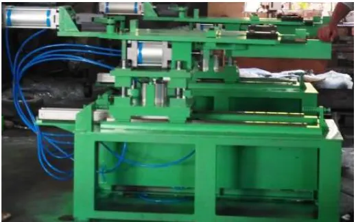
1. Pneumatics Cylinders:
There are the four cylinders which are using in this project. The first cylinder gives this linear To and Fro motion as per
the requirement of the process. The second cylinder is used to give the vertical motion to the machine along with the guide rod. The third cylinder is used to give to motion to the lower slider for clamping the job as per the requirement. And the fourth cylinder is used to give the expanding motion along with the expanding lever to the expanding jaws to hold the gear component. This all four cylinders are operated through the PLC unit which is fitted at the side of the machine with a frame. The pressurized air through the compressor is supplied to the pneumatic cylinders through the direction control valve. The fig. shows the different pneumatic cylinders.
Fig -1:- Pneumatic Cylinder.
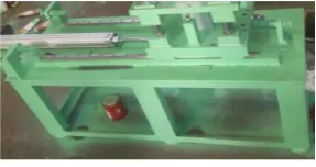
2. Structure and Bed
The structure is the foundation on which the whole machine is rest and bed performing the different task as well as gives the proper support to the different parts of the machine.
Fig -2 :- Bed Structure.
3. Guide rail support with the guide block
The guide rail support is used to give the motion of the upper body of machine to slide linearly from to and fro direction and the guide block which is attach to the upper body to slide over the guide rail.
4. Expanding jaws
The expanding jaws is used to give the support to the product to be weld and also provide the expansion as per the product size and shape to be weld in the welding machine.
[image:4.595.370.495.234.328.2] [image:4.595.362.506.432.508.2] [image:4.595.371.508.680.764.2]© 2018, IRJET | Impact Factor value: 6.171 | ISO 9001:2008 Certified Journal | Page 804 5. Top Center Plate
The top central plate is connected in between the expanding jaws and which gives the middle support to the product to be weld and both the expanding jaws are attached with this plate with certain arrangement.
Fig -4:- Center Plate.
6. Lowre Center Plate
The lower central slider is used as a final support or stopper to the job and at this point the job is weld.
Fig -5:- Lower Plate.
7. Gear clamp and Expanding levers:
The gear clamp is used as clamping jaws which is fitted over the expanding jaws and according to the gear blank size the gear clamp is set to provide the rigid support. And the function of expanding lever is to expand the expanding jaws through the upper cylinder motion.
Fig -6:- Clamping and Expanding Jaws.
6. CAD MODEL
[image:5.595.312.557.73.318.2]Fig -7:- Top View.
Fig - 8:- Front View
Fig -9:- Side View.
7. RESULT ANALYSIS
As per the conventional material handling into the welding machine there was so many difficulties are arise like cycle time should be more, productivity decreases because time for production increases, material loading is difficult by manual method and etc. in conventional method :
The time requires to load the job into the machine: t1= 30.3 sec
Time require to weld the ring gear: t2 = 20 sec
Time require to unload the job from the machine: t3 = 25 sec
There are so many job are not properly weld because the job is not properly loaded in the welding machine and hence the material wastage also increases. To avoid these drawbacks we manufacture the autoloader which is having following advantages:
The time requires to load the job into the machine: t1 = 16.7 sec
Time require to weld the ring gear: t2 = 20 sec
Time require to unload the job from the machine: t3 = 18 sec
If we consider the lot size is of 100 job to be weld so the time require:
By conventional method:
[image:5.595.85.239.157.241.2] [image:5.595.63.263.324.388.2] [image:5.595.83.238.504.582.2]© 2018, IRJET | Impact Factor value: 6.171 | ISO 9001:2008 Certified Journal | Page 805 Time required for 100 job to be weld = 75.3×100 = 7530 sec
= 125.5 min.
By the Autoloader machine:
Time required for one job to be weld = t1+ t2 + t3 = 16.7 + 20 + 18 = 54.7 sec
Time required for 100 job to be weld = 54.7×100 = 5470 sec = 91.16 min.
The reduction in production time = Total time require by conventional method -
Total time require by Autoloader
= 125.5 – 91.16
= 34.34 min
The Productivity of machine = 91.16 / 125.5
= 0.7263
Therefore the productivity increase by the Autoloader is 0.7263 times.
[image:6.595.35.295.405.567.2]8. ACTUAL MODEL
Fig - 10:- Actual Model
9. CONCLUSIONS
After analyzing whole conventional system to weld the gear, the problem was Arise that there was an accident happened because of the high current which is passing through the machine and at the time of welding there was direct contact between the man and machine.
As well as because of the conventional system scrap and rework were also increased and many difficulties were takes place.
So to overcome this drawback we concluded that to make a new version of the material handling system
and to make a machine which is free from any obstacles.
By using the Kaizen concept we make the Autoloader for welding the gear as there is the automatic clamping of gear is performed and the travel of the gear in the welding machine is also automatic.
By the use of machine we can improve the clamping method, as well as improves the quality of weld because as there is proper clamping is done so there is no chance of mis-weld of gear in the machine.
The time required for the complete operation is also reducing as there is the auto handling of part.
The human effort and direct contact between man and machine also reduced. .
ACKNOWLEDGEMENT
The authors are thankful to Guru Gobind Singh College of Engineering & Research center, Nashik, (GCOERC, Nashik) and her staff; and also to Prof.Sachin.v.Shinde, Dr Candrashekhar Mohod, Faculty of Mechanical Engineering Department, Savitribai University,Pune, for providing the necessary facilities for the preparation of the paper.
REFERENCES
[1] Shubhangi And P. Gurway, Implementation Of Kaizen As A Productivity Improvement Rool In Small Manufacturing Company, J. Information, Knowl. Res. Mech. Eng., Vol. 4, No. 1, Pp. 760–771, 2016.
[2] S. G. Dipak Gauri, Ajay Gajbhiye, Application Of Lean Kaizen In Productivity Improvement And Safety Measures In
A Manufacturing Industry, Nternational J. Eng. Res. Gen. Sci., Vol. 3, No. 2, Pp. 1302–1307, 2015.
[3] J.A. Bhoi, D.A. Desai, And R.M. Patel, The Concept & Methodology Of Kaizen, Int. J. Eng. Dev. Res., Vol. 2, No. 1, Pp. 2321–9939, 2014.
[4] T. M. Aurel, A. Simina, and T. Stefan, Continuous Quality Improvement in Modern Organizations Trough Kaizen Management, 9th Res. Conf. With Int. Particip. Quality 2015, Pp. 27–32, 2015.
[5] Imai Maasaki, Kaizen: The Kay To Japan’s Competitive Success. New York, USA: McGraw Hill, 1986.
[6] M. M. U. And P. B. Kishore Lad, Kedar, Productivity Improvement In Furniture Manufacturing Industry By Using Kaizen, Int. J. Sci. Dev. Res., Vol. 1, No. 4, Pp. 261–266, 2016.
[ ] Prošic Slobodan, Kaizen Management Philosophy, Int.
© 2018, IRJET | Impact Factor value: 6.171 | ISO 9001:2008 Certified Journal | Page 806 [8] M. Jakubiec and E. Brodnicka, Kaizen Concept In The
Process Of A Quality Improvement in the Company, Co. Today’s Eonomy - Theory Pract., Pp. 89–101, 2016.
[9] M. D. Singh, S. Singh, A. Chokshi, H. Chavan, And D. Dabhi, Process Flow Improvement Through 5s , Kaizen And Visualization, Int. J. Innov. Res. Sci. Eng. Technol., Vol. 4, No. 3, Pp. 1103–1112, 2015.
BIOGRAPHIES
Mr. Rushab D. Mitkar, was born in India. He is pursuing his Bachelor’s degree in Mechanical Engineering from Savitribai Phule Pune University. His current interests Product Design & Development.
Mr. Farhan H. Mansuri, was born in India. He is pursuing his Bachelor’s degree in Mechanical Engineering from Savitribai Phule Pune University. His current interests in Manufacturing and Industrial Management.
Mr. Hamza F. Attar, was born in India. He is pursuing his Bachelor’s degree in Mechanical Engineering from Savitribai Phule Pune University. His current interests Product Design & Development.
Mr.Kiran G. Konbde, was born in India. He is pursuing his Bachelor’s degree in Mechanical Engineering from Savitribai Phule Pune University. His current interests in Manufacturing and Industrial Management.