Performance Enhancement of MC-CDMA System
through Turbo Block Codes
Parvathy S Kumar , N. Kumaratharan
*Department of Information Technology, Sri Venkateswara College of Engineering, Irungattukotai – 602 117, Chennai, INDIA *Corresponding author: [email protected]
Copyright © 2013 Horizon Research Publishing All rights reserved.
Abstract
Multi carrier code division multiple access (MC-CDMA), a strong contender for future mobile communication is a combination of orthogonal frequency division multiplexing (OFDM) and code division multiple access (CDMA). Turbo coding technique can be used for improving the performance of MC-CDMA system in terms of bit error rate (BER). The objective of this work is to form a coding scheme that reduces BER of MC-CDMA system. In this paper a time domain turbo block code (TBC) designed using powerful low density parity check (LDPC) code is used in MC-CDMA system for improving the BER performance and the same is proved through simulation. This code also has error correction capability along with high performance efficiency in terms of BER.Keywords
LDPC code, MC-CDMA, Sum-product algorithm, Turbo block code1. Introduction
In wireless communications, the spectral limitation and distortion due to multipath channels are the main restricting problems, and the conventional CDMA is not efficient due to multipath fading. To combat these difficulties and to improve the system performance to achieve multiple access properties for communication networks, MC-CDMA systems are used [1].
MC-CDMA system is a combination of CDMA and OFDM. Hence MC-CDMA has the advantages of both CDMA and OFDM. The CDMA part increases spectrum utilization and the OFDM part reduces multipath fading and inter symbol interference (ISI). Even though MC-CDMA is more efficient when compared to other techniques, it has got some disadvantages like high PAPR and multiple access interference (MAI) which reduces BER performance of the system. To tackle these problems effectively, an efficient design of forward error coding (FEC) scheme is required for providing high coding gain. To obtain high coding gains with moderate decoding complexity, concatenation of codes with iterative decoding algorithms
has proved to be an attractive scheme; hence turbo block codes (TBC) can be employed. TBC uses a soft decision decoder which shows better performance when compared to hard decision decoders.
Several techniques were used to improve BER performance in MC-CDMA system, by reducing PAPR. Techniques like partial transmit sequence (PTS) [2], spreading code sharing M’ary PSK multi-carrier CDMA (SCS-MPSK-MCCDMA) system [3], a modified PTS scheme for uplink communications [4], optimum fixed subcarrier scrambling [5], cyclic shifted scramble code (CSSC) [6] were based on OFDM properties. These techniques used additional randomizing codes/sequences for reducing PAPR with additional computation at the IFFT modulator. This increased the system complexity, which lead to the development of more efficient MC-CDMA system exploiting the spreading codes, viz. spreading code redistribution [7], modified variable code sets (VCS) [8], spreading code reallocation (SCR) [9] etc. with reduced PAPR. The spreading codes are re-allocated or phase-shifted to obtain low PAPR in the foresaid techniques. Another technique reduces PAPR with an aid of peak reduction signals, which “borrow” the spreading codes of idle users [10]. Another technique used to improve BER performance of MC-CDMA system was nonlinear companding [11], a technique that transforms the amplitude or power of the original signals into uniform distribution to reduce PAPR.
Coding techniques offers excellent performance on BER reduction owing to fact of increased coding gain [12]. By using efficient coding techniques with error correction capability and high coding gain, system performance can be enhanced in terms of BER. TBC is different from traditional coding techniques; TBC decoder iteratively decodes the received code many times until required BER is obtained. Since decoding is done iteratively, BER performance can be improved without any additional hardware as error rate decreases further with iteration. A performance enhancement technique for MC-CDMA system through LDPC coding is proposed in this work.
LDPC coding are explained in Section III. The simulation results are presented in Section IV, and the conclusion is arrived at Section V.
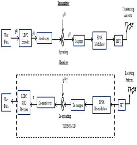
[image:2.595.57.296.425.677.2]2. MC-CDMA System using LDPC Code
The basic MC-CDMA signal is generated by a serial concatenation of classical DS-CDMA and OFDM [13]. Each chip of the direct sequence spread data symbol is mapped on to a different sub-carrier. Thus, with MC-CDMA the chips of a spread data symbol are transmitted in parallel on different sub-carriers, in contrast to a serial transmission with DS-CDMA. In MC-CDMA, the processing and spreading occurs in the frequency domain, rather than in temporal domain. Different users transmit over the same set of subcarriers but with a spreading code which maintains the orthogonality. The resulting signal has an orthogonal code structure in the frequency domain. If the number of and the spacing between subcarriers is appropriately chosen, it is unlikely that all of the subcarriers will be located in a deep fade and consequently frequency diversity is achieved. When the orthogonality of codes is disturbed while transmission, it results in MAI which will reduce the performance of the system. So to enhance the overall performance of the system the data is encoded using LDPC encoder at the transmitter and at the receiver it is decoded iteratively using a turbo decoder.Figure 1. MC-CDMA system using LDPC code
MC-CDMA system with K active users is shown in Figure 1. Let d(k) be one complex-valued data symbol assigned to kth user. At the transmitter side, the complex-valued data symbol d(k) is multiplied with the user specific spreading code of length L=PG ( where PG is the processing gain) to
spread the symbol.
The spreading code for kth user, c(k) is given by,
. (1) The chip rate (1/Tc) of the serial spreading code p(k) before serial-to-parallel conversion is,
(2) and is L times higher than the data symbol rate 1/Td.
The complex-valued sequence obtained after spreading is given in vector notations by,
(3) A multi-carrier spread spectrum signal is obtained after modulating the components; , l= 0,...,L−1, in parallel on to L sub-carriers. With multi-carrier spread spectrum systems, each data symbol is spread over L sub-carriers. In cases where the N number of sub-carriers of one OFDM symbol is equal to the spreading code length L, the OFDM symbol duration with a multi-carrier spread spectrum including a guard interval results in
. (4) In this case one data symbol per user is transmitted for one OFDM symbol.
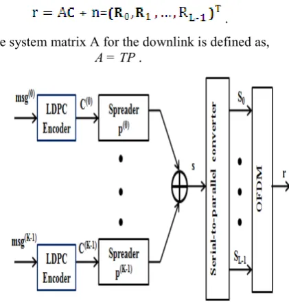
2.1. MC-CDMA Downlink Signal
The message signal is first encoded using LDPC encoder, the encoded signal is then spreaded and OFDM operation is performed to get the downlink signal. The superposition of the K sequences s(k) results in the sequence,
(5)
where C is the vector with LDPC encoded code words, (6) and P is the spreading matrix,
. (7) MC-CDMA downlink signal is obtained after processing the sequence s in the OFDM block. By assuming that the guard time is long enough to absorb all echoes, the received vector of the transmitted sequence s after inverse OFDM and frequency de-interleaving is given by,
, (8)
of the multi-user detection techniques, an equivalent notation for the received vector r is introduced,
. (9) The system matrix A for the downlink is defined as,
[image:3.595.68.279.104.325.2]A = TP . (10)
Figure 2. Downlink Transmitter
2.2. Uplink Signal
The received vector on the receiver side after inverse OFDM and frequency de-interleaving is given by,
r , (11)
where T(k) contains the coefficients of the sub-channels assigned to user k. The uplink is assumed to be synchronous in order to achieve the high spectral efficiency of OFDM. The vector r is fed to the data detector in order to get a soft estimate of the transmitted data. The system matrix, A comprises K user specific vectors.
) , (12) where a(k) is given by,
(13)
3. Low Density Parity Check Code
LDPC code is a class of linear block codes [14] which can be defined in terms of a sparse parity check matrix, H. For an m x n parity check matrix H, m rows specify the number of parity message bits, and n represents the length of a codeword. H is also characterized by Wr and Wc, which represent the number of 1’s in the rows and columns, respectively. Construction method for LDPC code can either be random (unstructured row-column connections) or structured (row-column connections will be pre-defined in
some way). Random constructions have flexibility in design and construction but lack regularity in row-column connection, which increases decoder complexity [14]
.
3.1. Random Construction of Parity Check Matrix forLDPC Code
The random constructions connect rows and columns of LDPC code matrix without any structured or predefined connection pattern. Constructions could also be made in tanner graph by connecting check nodes to variable nodes with edges or by replacing 0’s in check matrix with 1’s. Randomly adding edges to the Tanner graph or adding 1’s to parity check matrix will not produce desired rate and may have cycles of four. The resulting code will be then optimized by either post processing or by putting constraints on random choices. Post processing exchanges or deletes some connections in order to get a desired girth and rate. Random construction with constraints adds a connection in the code if it does not violate the desired girth or row column weights. Random codes have good performance especially at long code lengths compared to structured codes
Steps involved in implementing a randomly constructed LDPC codes are,
i. An all zero matrix H of dimension (m x n) is created. ii. For each column in H, three 1's are placed in rows
chosen at random, subject only to the constraint that the ones be placed in distinct rows.
iii. The matrix is then searched for a row with zero 1's or just one 1. If a row has no 1’s in it then it is a redundant row. Then 2 columns in the same row are chosen at random and places 1’s in those columns. If a row just has one 1 in a row it means that the codeword bit in that column is always zero. So another column in the same row should be randomly and a 1 is placed there. iv. The number of 1's per row should be calculated. Number
of 1's per row = (n x 3 )/m. If this is not an integer, round the value to the next higher integer.(If the number of 1's per row not an integer, it is not possible to have a uniform number of ones in each row).
v. Then the number of 1's per row should be made as uniform as possible. For any row (say ith row) containing
more number of one’s than the value calculated in Step 4, a column containing a 1 is picked at random and tries to move that 1 to a different row (randomly chosen such that it has lesser number of one’s than the value calculated in step 4) in the same column. It should be made sure that the row so chosen does not have a 1 in that particular column. If the software is not able to find such a row, it just tries with a different column containing a 1 in ith row.
vi. A good parity check matrix for LDPC codes generates a factor graph with no cycles in it. So try to eliminate cycles of length 4 in the graph.
matrix for irregular LDPC codes is generated. 3.2. LDPC Encoding
The encoding efficiency has quadratic complexity with respect to block length of the code, since it requires multiplication by the generator matrix which is not sparse. This complexity is in contrast to the turbo code case, which has linear encode complexity.
Steps involved in encoding a message u are as detailed, i. Let u be the message block to be encoded and H be the
parity check matrix of order (m x n); where m and n are the number of message bits and code length respectively.
ii. H should be in the form of an augmented matrix given by,
H=[I|B], (14)
where I is an identity matrix of order (m x m) and B is a matrix of order (m x (n-m))called parity.
iii. Original message u should be encoded to get the code word C (such that C.HT=0),
C = [c | s], (15) where c denotes check bits and s denotes the message bits.
iv. To find c;
A code word, C is said to be valid, if it satisfy the condition,
C . HT = 0 (16) From (14), (15) and (16); we have,
Ic + Bs = 0 (17) Therefore,
c =I-1Bs (18) 3.3. LDPC Decoding
LDPC decoder tries to reconstruct the transmitted codeword, C from the corrupted received word. It is achieved by using parity check matrix, H. The condition, CHT=0 defines the set of parity check constraints and this
condition must be satisfied for the received codeword to be the same as the transmitted codeword. Sum-product algorithm is used for decoding random LDPC codes in this work.
Sum Product Algorithm:
In sum-product decoding algorithm the values of the messages sent to each node are probabilistic denoted by log-likelihood ratio. What we receive are positive and negative values of a sequence. The signs of these values show the value of the bit supposed to be sent by the sender and the confidence in this decision is represented by a real value. For a positive sign it will send a 0 and for a negative sign it will represent a 1. Sum-product decoding algorithm use soft information and the nature of the channel to obtain the information about the transmitted signal.
If p is the probability of 1 in a binary signal, then the
probability of 0 will be (1−p). The log-likelihood ratio for this probability is defined as
(19) The probability of the result is the amount of LLR(p) , and the negative or positive sign of the LLR(p) represents the transmitted bit is 0 or 1. The complexity of the decoder is reduced by log-likelihood ratios. To find the upcoming probability for every bit of the received code word is the responsibility of sum-product decoding algorithm. Condition for the satisfaction of the parity check equations is that the probability for the ith codeword bit is 1. The probability achieved from event N is called extrinsic probability, and the original probability of the bit free from the code constraint is called intrinsic probability. If ith bit is assumed to be 1, this condition will satisfy the parity check equation then computed codeword i bit from the jth parity check equation is extrinsic probability.
There are three steps in sum-product algorithm; (i) Initialization
Communication to every check node 𝑗𝑗 from every bit node 𝑖𝑖 is called LLR of the received signal, "𝑦𝑦𝑖𝑖". The properties of the communication channel are hidden in this signal. If the channel is AWGN with signal to noise ratio Eb/N0 , this message will be like below.
(20) (ii) Check-to-bit
The communication of the check node with the bit node will satisfy the parity check equation if bit i=1, then LLR expressed as,
(21)
(iii) Code word Test
The resultant LLR is obtained by adding LLR’s from step one and step two.
Therefore the resultant LLR is,
(22)
(23)
This algorithm will terminate if for a valid code = Z1,Z2,...,Zn i.e. a code that satisfies the condition, 𝐇𝐇𝐙𝐙T=0 is obtained after a hard decision or if the maximum number of iterations is reached.
(iv) Bit-to-check
The communication of each bit node 𝑖𝑖 to the entire connected check node is the calculated by the LLR given as,
(24)
[image:5.595.111.187.80.119.2]The message is send back to second step after this step, i.e. the control goes back to the second step where the bit node receives the messages from check node.
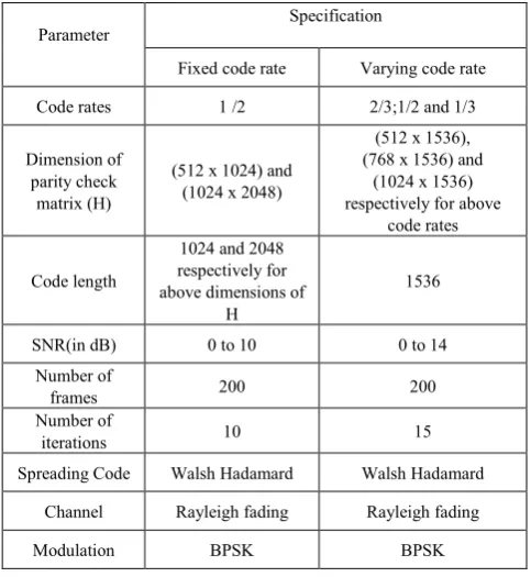
Table 1. Simulation Parameters for MC-CDMA System using LDPC Code
Parameter Specification
Fixed code rate Varying code rate
Code rates 1 /2 2/3;1/2 and 1/3
Dimension of parity check
matrix (H)
(512 x 1024) and (1024 x 2048)
(512 x 1536), (768 x 1536) and
(1024 x 1536) respectively for above
code rates
Code length
1024 and 2048 respectively for above dimensions of
H
1536
SNR(in dB) 0 to 10 0 to 14 Number of
frames 200 200
Number of
iterations 10 15 SpreadingCode Walsh Hadamard Walsh Hadamard
Channel Rayleigh fading Rayleigh fading Modulation BPSK BPSK
4. Simulation Results
The simulation results and comparisons of the proposed system were executed and analyzed using MATLAB version 7.12.0. BER performance of MC-CDMA system using LDPC code Rayleigh fading channel for different code rates and code lengths of LDPC code is evaluated. The code rate is fixed at 1/2 in first case where the dimension of the parity check matrix random of LDPC codes is changed and in second case the code rate is varied by keeping code length as a constant and it is fixed as 1536 bits. In first case as the dimension of parity check matrix increases performance will be improved and in second case as the code rate decreases
[image:5.595.324.533.143.335.2]performance will be improved. The input parameters chosen for the implementation of MC-CDMA system using random LDPC code using sum product algorithm for decoding is shown in the table I.
Figure 3. BER performance graphs of MC-CDMA System using LDPC
Code for different dimensions of Parity Check matrix
[image:5.595.57.299.322.585.2]Figure 3 shows the performance comparison of MC-CDMA system using random LDPC code for different dimensions of parity check matrix. The figure lists BER values of the system for varying SNR values. It is observed that as the dimension of parity check matrix increases the BER performance also increases; also the BER value decreases with increase in SNR value. The dimensions of the parity check matrix used here is 512 x 1024 and 1024 x 2048 with a fixed code a rate of 1/2.
Figure 4. BER performance graphs for MC-CDMA System using LDPC
Code with different Code rate
Figure 4 shows the performance comparison of Zi =
1, Li≤0 0, Li>0
0 1 2 3 4 5 6 7 8 9 10
10-4 10-3 10-2 10-1 100
SNR(dB)
BER
UNCODED LDPC(512X1024) LDPC(1024X2048)
0 2 4 6 8 10 12 14
10-4 10-3 10-2 10-1 100
SNR(dB)
BER
[image:5.595.326.538.502.700.2]MC-CDMA system using random LDPC code for different code rates. The figure lists BER values of the system for varying SNR values. It is observed that as the code rate decreases the BER performance increases; also the BER value decreases with increase in SNR value. The dimensions of the parity check matrix used here are 512 x 1536, 768 x 1536 and 1024 x 1536 for code rates 2/3; 1/2 and 1/3 respectively.
5. Conclusion
A TBC designed using LDPC code is proposed for MC-CDMA system to improve its system performance in terms of BER in this work. LDPC code enhances the BER performance with a quadratic encoding complexity and linear decoding complexity with respect to block length of the code. The simulation results and comparisons of the proposed system were executed and analyzed using MATLAB. BER performance of MC-CDMA system using random LDPC codes over Rayleigh fading channel for constant and varying code rates were analyzed. It was observed that the BER performance of the system increases with an increase in the dimension of parity check matrix and a decrease in code rate.
REFERENCES
[1] Aqiel N. Almaamory and Husam Abduldaem. Mohammed, Performance Evaluation and Comparison Between LDPC and Turbo Coded MC-CDMA, Journal of Engineering, vol. 18, no. 8, 2012
[2] N. Ruangsurat and R.M.A.P. Rajatheva, An Investigation of Peak to Average Power Ratio in MCCDMA Combined with Partial Transmit Sequence, Proc. IEEE VTC’01, pp. 761-765, 2001.
[3] Ginige. T, Rajatheva. N and Ahmed. K.M, Spreading code sharing MPSK-MC-CDMA system for low PAPR in wireless communications, IEEE VTC 2002-Fall, vol.2, pp. 666-670, 2002.
[4] Somchai Jitapunkul, Krittee Wutthipompong, Jirapa
Songthanasak and Suwich Kunaruttanapruk, Peak to Average Power Ratio Reduction in MC-CDMA using Partial Transmit Sequences, Wireless Telecommunications Symposium, pp. 03-08, 2004.
[5] Kwonhue Choi, Kunseok Kang and Sooyoung Kim, Peak Power Reduction Scheme Based on Subcarrier Scrambling for MC-CDMA Systems, ISSSTA, pp 326-329, 2004.
[6] Masato SAITO, Akihiro OKUDA, Minoru OKADA, and
Heiichi YAMAMOTO, Performance Evaluations of Multi-Carrier CDMA System with Cyclic Shifted Scramble Code in Multi-path Fading Channel, IEEE 9th ISSSTA, pp 74-78, 2006.
[7] E Alsusa & L Yang, MC-CDMA Specific PAPR Reduction Technique Utilising Spreading Code Redistribution, IEEE VTC/Fall, pp. 01 - 05, 2006.
[8] Sisi Liu, Lini Dan, Yue Xiao and Shaoqian Li, PAPR
Reduction Based on Improved VCS Scheme in MC-CDMA System, VTC -Spring, pp. 2672-2676, 2007.
[9] Lin Yang, Mingli You and Jun Li, Optimized Spreading Code
Reallocation Technique for PAPR Reduction in
MC-CDMA systems, IEEE GLOBECOM proceedings, pp 01-06, 2009.
[10] Luis A. Paredes Hernández and Mariano García Otero, User Reservation Approach for Peak-to-Average Power Ratio Reduction in MC-CDMA Systems, IEEE-VTC Spring, pp 01-05, 2009
[11] R.Manjith, S.C.Ramesh and M.Mohamed Ismail Majeed, PAPR Reduction In OFDM & MC-CDMA System Using Nonlinear Companding Techniques, IEEE Region 8 SIBIRCON, pp. 274 -278, 2010.
[12] Maryam Sabbaghian, Yongjun Kwak, Besma Smida and Vahid Tarokh, Near Shannon Limit and Low Peak to Average Power Ratio Turbo Block Coded OFDM, in IEEE transactions on communications, vol. 59, no. 8, , pp.2042 -2045, 2011
[13] K. Fazel and S. Kaiser, Multi-carrier and Spread Spectrum Systems from OFDM and MC-CDMA to LTE and WiMAX, Second Edition, A John Wiley and Sons Ltd. Publication, 2008.