20th International Conference on Structural Mechanics in Reactor Technology (SMiRT 20) Espoo, Finland, August 9-14, 2009 SMiRT 20-Division V, Paper 1942
Numerical Model of Thermal and Mechanical Behaviour of
a CANDU 37-Element Bundle
Lei Jiang
a, Ken MacKay
a, and Robert Gibb
ba
Martec Limited, Halifax, NS, Canada, e-mail: [email protected]
b
CNSC, Ottawa, Canada
Keywords: Finite Element, CANDU Fuel Bundle, Thermal and Mechanical Behaviour.
1
ABSTRACT
Prediction of fuel bundle deformations is important for assessing the integrity of fuel and the surrounding structural components under different operating conditions including accidents. For numerical simulation of the interactions between fuel bundle and pressure tube, a reliable numerical bundle model is required to predict thermal and mechanical behaviour of the fuel bundle assembly under different thermal loading conditions. To ensure realistic representations of the bundle behaviour, this model must include all of the important thermal and mechanical features of the fuel bundle, such as temperature-dependent material properties, thermal viscoplastic deformation in sheath, fuel-to-sheath interactions, endplate constraints and contacts between fuel elements. In this paper, we present a finite element based numerical model for predicting macroscopic transient thermal-mechanical behaviour of a complete 37-element CANDU nuclear fuel bundle under accident conditions and demonstrate its potential for being used to investigate fuel bundle to pressure tube interaction in future nuclear safety analyses. This bundle model has been validated against available experimental and numerical solutions and applied to various simulations involving steady-state and transient loading conditions.
2
INTRODUCTION
Investigation of the bowing deformation of fuel elements is important for assessing the integrity of fuel and the surrounding structural components under different operating conditions including accidents. The bowing of a fuel element is defined as the lateral deflection of the element from the axial centreline and the magnitude of bow is the maximum deflection between points of restraints. Bowing can have significant effects on performance and safety of the nuclear reactor. For instance, during normal operations, bowed fuel elements could reduce sub-channel flow area resulting in poor heat transfer due to local coolant starvation, causing these elements to deflect as a result of local overheating. Under accident conditions, bowing of fuel elements can lead to safety concerns for fuel coolability and the pressure tube integrity.
The integrity of the pressure tube under accident conditions is a requirement for effective trips in CANDU reactor design. As a result, an understanding of all of the behaviours of the pressure tube in various different accident scenarios is crucial for understanding the trip effectiveness. One of the important pressure tube behaviours that need to be investigated is the coupled thermal-mechanical interaction between the fuel bundle and pressure tube. In the early stages of a loss of coolant event, it is known that fuel bundles deform or barrel so that the outer elements bend outward. But the magnitude of the distortion is not readily quantifiable. The bundle barrelling could result in the bundle coming into increased contact with the pressure tube. If this were to happen, the contact force between bearing pads and the pressure tube would be increased which increases the contact area on the bearing pad and pressure tube, and enhances the heat transfer from the fuel elements to the pressure tube, creating localized hot spots and high stress areas. The combination of higher temperature and higher local stress could lead to pressure tube failure. If this were the case, then the likelihood and numbers of pressure tube failures in loss of coolant and other accident conditions would be greater than presently predicted. This would significantly affect the current under-standing of margins to severe core accidents.
bundle assembly under different accident conditions. In order to ensure realistic solutions, all the key thermal and mechanical features of the fuel bundle, such as temperature-dependent nonlinear material properties, fuel-to-sheath interactions, endplate constraints and contact between fuel elements, need to be included.
The attempt for predicting fuel bundle deformations due to bowing/bending of fuel elements started three decades ago. In 1974, Veeder and Schankula (1974) presented a thermal-mechanical analysis method for predicting bowing of pelletized fuel elements. They realized that the bowing deformation was due to a temperature distribution asymmetry with respect to the axis of the fuel element, caused by non-uniform coolant temperature, variable sheath-coolant heat transfer coefficient and asymmetric heat generation due to neutron flux gradients across an element. They formulated a 2D steady-state heat transfer problem to predict the asymmetric temperature field and utilized it to compute equivalent bending moments which eventually led to deflection of the fuel element. These predictions were found to be in qualitative agreement with the in vitro experimental data. However, this procedure contained serious limitations due to simplifications on material properties and fuel stiffness. In particular, it required a scaling factor G, which describes how tight the sheath “grips” the fuel and is very difficult to quantify.
An improved analysis procedure for predicting bowing deformation of nuclear fuel elements was presented by Tayal (1989) based on which a specialized finite element program, named BOW, was developed. Comparing this model to the simple bowing model presented by Veeder and Schankula (1974), the BOW program provided more advanced modelling capabilities, such as the additional bending moments due to hydraulic drag and gravitational forces, the flexural rigidity of the fuel pellets, the temperature-dependent thermal-mechanical material properties and the change in metallurgical phases. The endplate, the concentric and eccentric welds between the endplate and endcaps and the fuel element to pressure tube contact were also included. Although the BOW code is a very valuable numerical tool for predicting bowing distortions, it has some limitations. First of all, because the temperature field was still calculated using a two-dimensional planar steady-state heat transfer model, the axial heat flux and temperature variations were neglected completely. Secondly, as the purpose of the BOW code was to predict the magnitude of bow deflection under normal operation conditions, the transient temperature distribution and thermal-induced deformations of the fuel bundle were not predicted. In other words, the BOW code could not be readily used to simulate bundle behaviour under accident conditions. Thirdly, the BOW program required two user-supplied factors, namely Curvature Transfer Factor (CTF) and Rigidity Enhancement Factor (REF), to characterize the interaction between the fuel pellets and the sheath inside a fuel element. The values of these parameters were difficult to determine in practical calculations. In addition, because of the existence of these two scaling factors, extension of the BOW code to nonlinear analyses became more difficult. Following the first release of the BOW code, a number of attempts have been made to improve its capability. These included implementation of new analysis features and modelling options (Yu, Tayal and Singh, 1995) and a number of viscoplastic material models (Yu, Tayal and Xu, 1997) to predict creep-induced bowing. However, in these models, the temperature field was assumed to be constant, so the thermo-viscoplastic behaviour of Zircaloy-4 could not be easily considered. In order to help determine the curvature transfer factor (CTF) required by the BOW code, an axisymmetric formulation was developed to solve the multi-body contact problem involved in a fuel element (Yu, Xu and Yang, 2004). However, their formulation presented was based on assumptions of small thermo-elastic deformation, linear elastic material properties and axially uniform temperature distributions. Many of the important factors, such as temperature-dependent material properties, large displacements, finite plastic strain and axial temperature variations, were not included. In addition, no direct connection was given between the axisymmetric finite element solutions and the value of CTF.
In addition to beam finite element based approaches described above, attempts were also made to study the bundle behaviour using solid elements provided in commercial finite element codes, such as ANSYS (Walters and Williams, 2003). However, at the present time, this 3D solid element model of complete fuel bundle still limited to linear elastic material properties and steady-state loading conditions.
constraints provided by the endplates and contact between the spacer pads, were included in this bundle model. The robustness and reliability of the developed finite element bundle model were verified using numerical examples involving extreme steady-state and transient loading conditions.
3
DEVELOPMENT OF FINITE ELEMENT MODELS OF FUEL BUNDLE
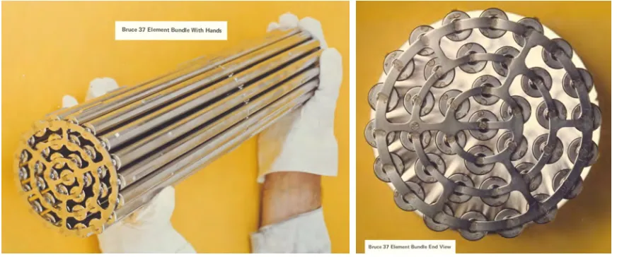
A picture of a 37-element CANDU fuel bundle identified on the Internet is displayed in Fig. 1. This picture shows the various fuel bundle components: fuel elements, endcaps, endplates, bearing pads and spacer pads. All of these structural components need to be included in the finite element model.
Figure 1: A Typical 37-element CANDU fuel bundle.
The finite element model developed in the present contract is based on Martec’s VAST finite element program suite (Martec Limited, 2008). VAST is a general-purpose finite element solver engine utilized in Martec’s commercially available Trident-FEA package, which is capable of doing nonlinear dynamic analyses with a wide selection of element types and material models. VASTF is a finite element program for nonlinear steady-state and transient heat transfer analysis in the VAST program suite. Recently, the VAST suite of programs were significantly improved by creating new analysis modules that account for the thermal and mechanical properties of the fuel and sheath materials used in CANDU nuclear fuel elements (Jiang and MacKay, 2006).
The nature of the numerical simulations attempted in the present work requires analysis of both the thermal and structural behaviour of the fuel bundle during various accident transients. Including all of these effects in a single finite element model is not practical. Therefore, we have decided to represent the thermal and mechanical behaviour of the fuel bundle using separate models. Among them, two finite element models were utilized for heat transfer analyses. The first was a 2D axisymmetric model, referred as Model A, which was responsible for characterizing temperature variation along the length of fuel elements. The other model (Model B) was a 2D planar model representing a middle cross-section of the fuel bundle and was used to predict two-dimensional asymmetric temperature field in fuel elements during the entire accident transients. The transient temperature fields generated by the 2D axisymmetric model (Model A) and the 2D planar model (Model B) were then combined to provide an approximate 3D transient temperature field that was required for formulating the equivalent forces for mechanical calculations. The macroscopic behaviour for thermal-induced transient deformations of the fuel bundle was computed by a 3D beam element model. All the key features of the fuel bundle listed above were all addressed in this 3D beam element model.
3.1 Axisymmetric and 2D Planar Heat Transfer Models
mixing, (2) a circumferentially variable heat transfer coefficient between the fuel element and coolant and (3) asymmetric heat generation due to neutron flux gradients. In the present study, the uneven coolant conditions and the radial variation of the power generation rate were extracted directly from the input and output files of the thermal-hydraulic code ASSERT, and utilized in the VASTF heat transfer analyses.
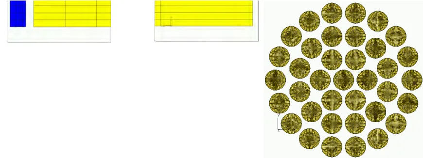
Both the axisymmetric and 2D planar heat transfer elements implemented in VASTF are capable of modelling temperature-dependent thermal properties, time-dependent thermal boundary conditions and internal heat generation, and can be readily used to represent the fuel and sheath under transient thermal load conditions. To properly describe the heat transfer between the fuel and the sheath, special interface elements were developed. In Model B, 300 4-noded quadrilateral planar elements were utilized to idealize the cross-section of a fuel stack and each sheath cross-cross-section was represented by 40 elements. The fuel-sheath interface was modelled by 40 interface heat transfer elements.
4 mm 4 mm 12 mm
4 mm 4 mm 12 mm
4 mm 4 mm 12 mm
4 mm 4 mm 12 mm
Figure 2: Axisymmetric (Model A) and 2D planar (Model B) models for heat transfer analyses.
To formulate the heat transfer problem for steady-state and transient analyses of fuel bundles, the power scaling function, which describes the variation of power generation rate along the radial direction of the fuel
bundle due to neutron flux gradient, must be extracted from the ASSERT input file (Waddington et al,
2004). The non-uniform coolant temperature and coolant-to-sheath heat transfer coefficient also need to be calculated from the sub-channel temperature and sheath-to-coolant heat flux produced by ASSERT simulations. For transient analyses, the time histories of these power and coolant conditions need to be
obtained from CATHENA analyses (Beuthe et al, 2000). The detailed data extraction procedure was
described by Jiang and MacKay (2007). Once the asymmetric temperature fields for middle sections of all fuel elements were obtained, they were combined with the axisymmetric temperature distribution obtained using Model A to form a full three-dimensional time-dependent temperature field for the entire fuel bundle.
Although this heat transfer model shown in Fig. 2 already includes all the fuel rods in a bundle, there was still one important structural component missing, the endplates. The endplates could not be readily added to either the 2D planar or the axisymmetric models, because the axisymmetric model contained only a single fuel element, whereas the 2D planar model only included the middle section of the fuel bundle. In addition to the difficulty associated with the finite element modelling procedure, the physics behind the heat transfer between coolant and endplate was not well understood either and no reliable measurement of the coolant-to-endplate heat transfer coefficient was identified in the literature. This is probably due to the extremely complicated flow pattern in the area. In the BOW code, the endplate temperature was set to the coolant temperature. The same approximation was adopted in the present work.
3.2 3D Beam Element Model for Deformation Analysis
cells. Material properties for plastic deformation and thermal expansion were defined for each of the cells independently. Please refer to Jiang and MacKay (2007) for details of the beam formulation.
For calculating the equivalent nodal force vector resulting from the temperature variation in the beam element, integration over the element volume was performed In the present finite element model, the approximate 3D temperature field obtained from the heat transfer analyses was mapped to the beam element to compute the thermal-induced nodal forces and moments, which cause bowing of the fuel elements.
In order to provide the flexibility for properly expressing the mechanical interaction between the fuel and sheath/endcap, each fuel element was represented by two rows of beam elements in the present bundle model, presenting the fuel stack and the sheath/endcap, respectively. The nodes in these two beam element meshes overlapped in space, but were associated with independent node systems, so the deformation patterns of the fuel and sheath were not necessarily identical. The effect of thermal expansions in both fuel and sheath were treated independently through consistent thermally-induced equivalent nodal force vectors. The temperature-dependent thermal and mechanical material properties were considered and in particular, the nonlinear thermal-viscoplastic property of Zircaloy-4 (Sills, 1979) was employed in the beam element model to accurately characterize material behaviour of the sheaths and endcaps under transient loads. The endcaps, which has an axisymmetric geometry, was conveniently modelled by beam elements with different circular cross-sections.
As in all bowing models developed so far, pellet hourglassing was ignored in the present analysis. The pellet stack was treated as continuous and in hard axial contact by compressive forces from pellet/endcap interaction. As the stack behaviour for the scenarios simulated was controlled by the "cold" pellet rim, this approximation was reasonable. On the other hand, in the absence of sheath bambooing and pellet hourglassing models, only full contact and no contact between the fuel and sheath could be simulated in a meaningful way. The axisymmetric analysis results obtained by Jiang and MacKay (2006) indicated that during the first 10 seconds in a LOCA transient, the fuel remained in contact with the sheath and endcap. Because the present simulation was focused on the same time scale, a full interaction between the fuel and sheath/endcap has been assumed in this study. This was achieved by enforcing displacement compatibility conditions between the two beam-element meshes described above through multi-point constraint equations.
To verify the accuracy of the current beam element model of a single fuel element, a series of test cases were considered. The first test case involved axial deformation of the fuel element, in which one end of the fuel element was constrained against motion in the axial direction and the other end was loaded by an axial force. The axial stiffness of the fuel element was obtained by dividing the applied load by the axial nodal displacement at the loaded point. The axial stiffness of a fuel element in a typical CANDU fuel element was
previously calculated during the Darlington N12 investigation (Lau et al, 1992). Two cases were considered
in that study. The first case was cold (20oC), unpressurized and unirradiated conditions. In this case, the fuel
element deformed as an empty sheath and its axial stiffness was found to equal to 3.2 MN/m approximately.
The second case was under pressurized (10.7 MPa), hot (290oC) and high-power conditions. Under these
conditions, a full interaction between the fuel and sheath occurred and the axial stiffness increased to approximately 47 MN/m. In this study, the present beam model of fuel element was used to predict axial stiffness values in these two cases and the VAST results agreed with the published solutions as shown in Table 1.
Table 1: Test cases for calculating axial stiffness of a fuel element
Axial Stiffness (MN/m) VAST Lau et al (1992)
Empty Sheath (20oC) 3.13 3.2
Sheath and Fuel (290oC) 48.59 47
this slender beam structure was significantly lower than its axial stiffness given in Table 1 and the boundary condition had a very significantly effect on the bending behaviour, which confirmed the importance of accurate modelling of the endplates.
Table 2: Test cases for calculating bending stiffness of a fuel element
VAST Yu et al (1995)
Bending Stiffness (KN/m) SS Clamped w/o endplate w/ endplate
Empty Sheath (20oC) 12.6 50.8 11.9 17.0
Sheath and Fuel (290oC) 103.0 332.6 N/A N/A
No published results on bending stiffness of the fuel element were identified in the literature for
comparison with the VAST prediction. Fortunately, in a paper by Yu et al. (1995), experimental and
numerical results for load-deflection curves of a cool empty sheath under bending deformation were presented. In this experiment, a single CANDU 6 fuel bundle was held horizontally on a load frame at room temperature, with one of the outer elements pulled radially upward at the mid-plane. The radial deflections of the loaded fuel element were measured at the middle and end points. The constraining effect of the endplate was clearly included in these results, but in the paper, an analytical solution was also provided for load-deflection behaviour without the effect of the endplate. This later solution was comparable with the present result obtained using the simply supported boundary conditions. The bending stiffness values extracted from the plot in Yu et al. (1995) are also given in Table 2. The result without the endplate is in very close agreement with the present prediction with the simply supported boundary condition. The bending stiffness
with the endplate published in Yu et al (1995) is between the present predictions using clamped and simply
supported boundary conditions.
The endplate was also modelled using beam elements. The mesh density was determined through a convergence study. A nonlinear analysis was conducted with both geometric nonlinearity and elastic plastic deformation at room temperature. In this analysis, the outer ring was constrained at all endplate-to-endcap connection points, and the centre of the endplate was prescribed an out-of-plane displacement up to 2.0 mm. The predicted final deformed configuration and load-deflection curve were very reasonable.
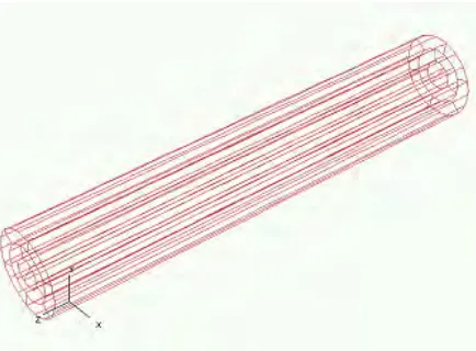
The complete fuel bundle model is displayed in Fig. 3. In this model, the fuel element models and the endplate models were connected using rigid links, which enforced displacement compatibility at the connections. The mechanical interactions between the fuel elements through spacer pads were modelled using gap elements. This 3D bundle model contained 2740 nodes and 2686 beam finite elements. The boundary conditions on this beam element-based bundle model contained constraints at the centres of both endplates. In particular, at the right end, three translational degrees of freedom and the axial rotation are constrained, but at the left end, constraints are only applied to translations in X and Y-directions, permitting the bundle to expand freely along the axial (Z) direction. These boundary conditions represent minimum constraints, which only remove rigid body motions from the system, but not causing any additional straining in the structure.
4
BUNDLE DEFORMATION UNDER STEADY-STATE CONDITIONS
Two steady-state cases were employed to test the behaviour of the present 37-element CANDU fuel bundle model. Case I seeks a condition where flow is stratified and temperatures in the steam region are elevated. Conditions for this case are approximately 12 MPa pressure, 3.75 kg/s channel flow, inlet temperature of 305°C and 3.5 MW channel power. Case II is to create a coolant condition where coolant is mostly steam and is at high temperatures. Conditions for this case are approximately 4 MPa, 2.0 kg/s, 230°C inlet
temperature and channel power of 6.17 MW. For these two cases, the asymmetric coolant conditions were calculated from the ASSERT output files. The extracted thermal conditions included the averaged coolant temperature and overall sheath-to-coolant heat transfer coefficient in each sub-channel for each of the 37 fuel elements.
By reviewing the asymmetric coolant conditions generated from ASSERT files, it was realized that the two steady-state heat transfer cases chosen for the present work have different characteristics. For instance, in the first case, the coolant temperature was almost uniform over the entire cross-section of the bundle, but the heat transfer coefficient decreased significantly from the bottom to the top of the bundle because for the given condition, the coolant for the upper part of the bundle was in vapour phase whereas the coolant for the lower part of the bundle was still in liquid phase. In the second case, the heat transfer coefficient was quite uniform over the bundle cross-section, but the coolant temperature varied considerably. The highest coolant temperature occurred at the centre of the bundle.
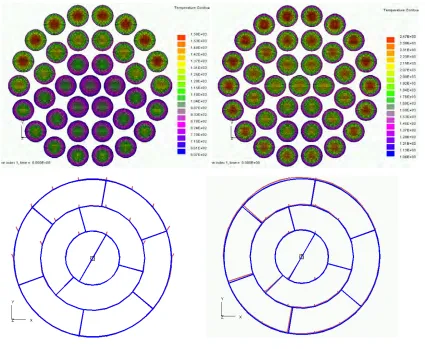
The predicted temperature distributions in the middle section of the fuel bundle under these steady-state thermal load conditions are given in Fig. 4 and 5, where the corresponding deformed configurations are also given. In the deformation plots, end view of the original (blue) and deformed (purple) bundle geometries are superimposed. For Case I, higher sheath temperatures were predicted for elements located in the upper part of the cross-section due to reduced sheath-to-coolant heat transfer coefficient. For these fuel elements, the sheath temperatures on the side facing downwards were lower than the sheath temperature on the side facing upwards. This temperature gradient drove the fuel elements to bow upwards as indicated in the lower plot in Fig.4. Due to the interaction between the fuel elements, the amplitudes of the barrelling deformation became quite uniform over the upper part of the bundle cross-sections. In Case II, the hotter coolant temperature at the bundle centre resulted in higher sheath temperature on the side of the fuel element facing the centre of bundle making the fuel elements bow inwards forming a hourglass deformation mode. However, due to
Figure 4: Results for steady-state test case I.
interactions between the fuel elements, the inward bending of the elements in outer rings were constrained by the inner elements and the contact forces were transferred to the endplates causing significant endplate deformations, as shown in the lower plot in Fig. 5.
5
BUNDLE DEFORMATION UNDER TRANSIENT CONDITIONS
Two representative loss-of-coolant accident (LOCA) cases were considered. Both cases were assumed to have the same power pulse function and sheath-to-coolant heat transfer coefficient, so the only difference was the time history of coolant temperature. In LOCA case I, the coolant temperature was assumed to be uniform over the entire fuel bundle. In the second LOCA case, the coolant was assumed to contain gas and fluid phases and the fluid level varied with time. The coolant temperature of the fluid phase decreased monotonically from the onset of accident. However the gas phase coolant became significantly hotter and
reached a peak temperature in about 3.5 seconds. The water level dropped quickly at t=1 second, but reached
a constant value at t=2 second. From that point, the very bottom fuel rods, as indicated in Fig. 6 and 7, was
exposed to both the gas and fluid coolants, causing a very significant variation of coolant conditions along the circumference. This highly asymmetric coolant temperature distribution has a great influence on the barrelling deformation of this fuel element.
To predict transient bundle deformations using the present numerical model, steady-state heat transfer analyses were first performed to obtain temperature distributions in the entire fuel bundle under the normal operation conditions and these steady-state solutions were subsequently employed as initial conditions for the transient heat transfer runs under given accident conditions. The predicted transient temperature fields by using the axisymmetric and 2D planar models were then combined to formulate 3D approximations of the transient temperature distribution, which were mapped to the beam element bundle model to compute LOCA induced deformations. For each of the LOCA cases, two deformation analyses were performed in which the mechanical properties of the sheath/endplate materials, Zircaloy-4, were modelled using either linear elastic or thermal-viscoplastic material models.
Representative results from the heat transfer and deformation analyses of the 37-element bundle under different LOCA conditions are given in Fig. 6 and 7, including deformed configurations at different times of the loading process. Also shown are the time histories of the difference between temperatures on the top and bottom of the fuel element indicated in the deformation plot and the time histories of the amplitudes of the barrelling displacement of the same fuel element. Examination of these displacement time histories led to a number of interesting observations. First of all, the peak barrelling displacement occurred at the same time as the peak sheath temperature difference, which suggested that the temperature gradients in the fuel rods were the primary driving force of the barrelling deformation. Secondly, the solutions obtained using linear elastic and thermal viscoplastic material models for Zircaloy-4 were similar, indicating the magnitude of plastic deformations was relatively small in these particular LOCA cases.
As shown in Fig. 6, the uniform coolant temperature in LOCA case I resulted in a nearly axisymmetric deformation pattern of the fuel bundle. However, the deformation patterns in LOCA case II were more complicated. Comparing these deformed shapes with those predicted for the previous LOCA case, it is
readily recognized that for up to t=2 second, the deformation patterns predicted in both cases were similar,
t=2s t=6s -80 -60 -40 -20 0
0 2 4 6 8 10
Time (sec) Vertical Temperature Difference (K) -2.5 -2.0 -1.5 -1.0 -0.5 0.0 0.5
0 2 4 6 8 10
Time (sec) Vertical Barreling Amplitude (mm) Elastic Viscoplastic t=2s t=6s -80 -60 -40 -20 0
0 2 4 6 8 10
Time (sec) Vertical Temperature Difference (K) -2.5 -2.0 -1.5 -1.0 -0.5 0.0 0.5
0 2 4 6 8 10
Time (sec) Vertical Barreling Amplitude (mm) Elastic Viscoplastic t=2s t=6s -80 -60 -40 -20 0
0 2 4 6 8 10
Time (sec) Vertical Temperature Difference (K) -2.5 -2.0 -1.5 -1.0 -0.5 0.0 0.5
0 2 4 6 8 10
Time (sec) Vertical Barreling Amplitude (mm) Elastic Viscoplastic
Figure 6: Typical transient analysis results for LOCA case I.
-80 -40 0 40 80 120
0 2 4 6 8 10
Time (sec) Vertical Temperature Difference (K) t=2s t=6s -2.5 -2.0 -1.5 -1.0 -0.5 0.0 0.5 1.0 1.5
0 2 4 6 8 10
Time (sec) Vertical Barreling Amplitude (mm) Elastic Viscoplastic -80 -40 0 40 80 120
0 2 4 6 8 10
Time (sec) Vertical Temperature Difference (K) t=2s t=6s -2.5 -2.0 -1.5 -1.0 -0.5 0.0 0.5 1.0 1.5
0 2 4 6 8 10
Time (sec) Vertical Barreling Amplitude (mm) Elastic Viscoplastic
6
CONCLUSIONS
Numerical studies presented in this paper demonstrate that the present finite element based fuel bundle model is reliable and predicts credible bundle behaviour in response to accident type conditions in a fuel channel. Note, however, the ability of the present model to predict accident behaviour is limited by lack of knowledge of many of the sub-phenomena; two examples are fuel column rigidity and effect of endcap welds on endplate rigidity. The intended application of this model is to assess pressure tube integrity in large break loss of coolant accidents. An evaluation of the completeness of the models and how the application should be performed is the next step towards this goal.
REFERENCES
Beuthe, T.G. and Hanna, B.N. 2000 “CATHENA MOD-3.5c/Rev 0 Theoretical Manual”, COG-00-008,
CANDU Owners Group Inc.
Jiang, L. and MacKay, K. 2006 “Fuel Failure Mechanisms Under Accident Conditions”, Martec Technical Report TR-06-14, Martec Limited, Halifax, Nova Scotia.
Jiang, L. and MacKay, K. 2007 “Numerical Model of the Thermal and Mechanical Behaviour of a CANDU 37-Element Bundle”, Martec Technical Report TR-07-49, Martec Limited, Halifax, Nova Scotia.
Lau, J.H.K., Tayal, M., Nadeau, E., Pettigrew, M.J., Oldaker, I.E., Teper, W., Wong B. and Iglesias, F. 1992 “Darlington N12 Investigation- Modelling of Fuel Bundle Movement in Channel Under Pressure Pulsing Conditions”, Presented at the CAN Annual Conference.
Martec Limited, 2008, VAST User’s Manual, Version 8.8.
Sills, H.E. 1979 “ELOCA – Fuel Element Behaviour During High-Temperature Transients”, AECL-6357, AECL, Chalk River, Ontario.
Tayal, M. 1989 “Modeling of Bending/Bowing of Composite Beams such as Nuclear Fuel: The BOW Code”, Nuclear Engineering and Design, Vol. 116, P. 149-159.
Veeder, J. and M.H. Schankula, M.H. 1974 “Bowing of Pelletized Fuel Elements: Theory and In-Reactor Experiments”, Nuclear Engineering and Design, Vol. 29, P. 167-179.
Waddington, G.M., Rao, Y.F., Bunama, R. and Pfeiffer, P. 2004 “ASSERT-PV IST V3R1 User’s Manual”,
RC-2913/RSD-TH-007, AECL Thermalhydraulics Branch.
Walters, L.C. and Williams, A.F. 2003 “Fuel Bundle Deformation Model”, Presented at the Eighth International Conference on CANDU Fuel, Toronto, Canada, Sept. 21-24.
Yu, S.D., Tayal, M. and Singh, P.N. 1995 “Improvements, Verifications and Validations of the BOW Code”, Presented at the Fourth International Conference on CANDU Fuel, Pembroke, Canada, Oct. 1-4, P. 4B.38-51.
Yu, S.D., Tayal, M. and Xu, Z. 1997 “Creep Bowing in CANDU Fuel: Modelling and Applications”, Presented at the Fifth International Conference on CANDU Fuel, Toronto, Canada, Sept. 21-25, P. 364-375.