Efficient Priority Energy Load Management
Using MATLAB
Yugandhara G. Wankhade1, Dr. Ujwala A. Kshirsagar2
M. E Student, Department of Electronics and Telecommunication, HVPM’s College of Engineering and Technology,
Amravati, Maharashtra, India1
HOD, Department of Electronics and Telecommunication, HVPM’s College of Engineering and Technology
Amravati, Maharashtra, India2
ABSTRACT: There might be load surges or flying out a few times in the ventures. In this venture we propose the need driven the heap administration utilizing computerization systems. We can appoint the need to the heap as indicated by its tendencies, parameters and significance. We utilize this need for choosing and load which is to be utilized for computerization. This mechanization reason for existing is fulfilled by and for setting need we have one hand-off driving circuit associated with atmega328. We pre characterize the need of the framework and as indicated by that need we dole out the vitality to the heap.
In this system the wireless communication link is made possible between the RF remote and the control board with the help of RF communication. RF is ideal for effective and long distance wireless communication. The RF remote receives the commands from the PC through the serial communication link and is transmitted into the air. Here the command denotes the on or off conditions of the home appliances. Each and every device connected to the power grid has its own separate command for the on and off conditions. The control board which is attached to the power grid control section in the home/industry consists of a RF receiver. This receives the commands transmitted by the transmitter and are given to the microcontroller. The microcontroller plays a major role in receiving the commands from the RF receiver module and to switch on or off the particular device according to the command. Here in this project a power grid is connected to control up to four devices.
KEYWORDS:Load Shedding, Priority, Load Management, RF Transceiver, Atmega328, MATLAB GUI
I. INTRODUCTION
of power depends on the load. The total load of the system is the sum of the maximum load required by the entire regions and loss. If any region requires additional power to meet the load requirement, system checks the regions with their maximum load. This comparison helps us to find the minimum load required units and schedule this load to the required region. The system never interrupts the power source. In this project we suggest the priority driven the load management using automation techniques. There may be load surges or popping out some times in the industries. We can assign the priority to the load according to its natures, parameters and importance. We use this priority for selecting and load which is to be used for automation. This automation purpose is satisfied by setting priority we have one relay driving circuit connected with microcontroller. We pre define the priority of the system and according to that priority we assign the energy to the load. Main aim of the project work is to reduce the power generation cost and make the availability of power on demand without any distortion so as to get required efficient power to the main load needed in the application.
1. Objective
The proposed system has its directive to provide effective load management to deal with the load shedding problems also gives innovative priority mechanism which indirectly reduces man power which is specifically needed to supervise the applications. A priority load management system has been developed in order to gain an optimal energy management over system load and battery storage, and therefore provides better management efficiency and guarantee the energy supply for critical load, by considering industrial applications this system makes them self reliable, at least, to use the appliances to operate automatically during load shedding problems.
II. LITERATURE REVIEW
As the new technology evolved it demands for more and more power sometimes it is difficult to fulfill this power requirement. So from many years research on power management is going on for this some litratures are focused on the topic of power management and the aim of the research work is to reduce the power generation cost and make the availability of power on demand without any distortion.
Shervin Shokooh, Tanuj Khandelwal, Dr. Farrokh Shokooh, Dr. JJ Dai, Jacques Tastet had mentioned in their paper published on topic ‘Intelligent Load Shedding Need for a Fast and Optimal Solution’ that intelligent load shedding system can provide faster and optimal load relief by utilizing actual operating conditions and knowledge of past system disturbances and conclude that load shedding serves as the ultimate guard that protects the power system from a disturbance-induced collapse. Also introduce an intelligent, optimal, and fast load shedding technology referred to as ILS. ILS combines online data, equipment ratings, user-defined control logics, and a knowledgebase obtained from power system simulation studies, to continually update dynamic load shed tables. This system can perform optimal load shedding in less than 100 milliseconds from the initial occurrence of a disturbance. ILS technology has been successfully installed and operational at several industrial facilities.
Vijo M Joy, S Krishnakumar published the paper on topic ‘Efficient Load Scheduling Method For Power Management’ and focused on an efficient load scheduling method to meet varying power supply needs & by scheduling the load based on the requirement of the system having outcome as perform the scheduling of power generators based on the availability and cost, if we reduce the number of power generators then the execution time decreases
Control. The results demonstrated that control case has a better performance, keeping the priority load connected and protecting the battery bank from over discharge and reducing loss of power supply probability.
In 1975 Carl E. Landwehr discussed on an Endogenous Priority Model for Load Control in Combined Batch in which a relatively high level analytical model for computer systems serving both and interactive users is presented. The model is unusual in its employment of an endogenous priority scheme to represent a class of strategies for controlling service to the different customers. Hence conclude that the model developed is capable of representing computer systems which include algorithms for controlling service delivered to batch and interactive users has been demonstrated by the validation and parameter studies.
Abubakar, S. N. Khalid, M. W. Mustafa, Hussain Shareef and M. Mustapha had focused on the application of load monitoring in appliances ‘ energy management and introduces the current state of art of appliances energy management through Intrusive Load Management(ILM) and Non- Intrusive Load Management(NILM) where ILM is distributive and NILM is a single point sensing and conclude that these techniques to be used in minimizing the energy consumption of the building for the purpose cost saving and minimizing the green house gas emission.
III.RELATEDWORK
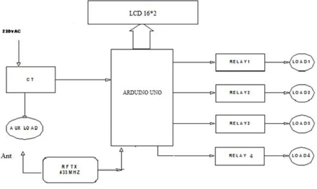
Priority system consists of ARDUINO UNO board having ATMEGA328 microcontroller as its main component which controls the whole mechanism. The blocks of priority load management system are shown in following figure, with their description.
Fig 1. Transmitter Section
Above Priority load management System consists of 2 section, viz. Transmitter Section, and Receiver section which are described as below.
Now days, there is a lot of requirement to control the appliances in an industry or in a home connected to the power grid when we are working with our PC. In these situations we need to go to the place where the power grid has been situated which is a time consuming process. The main aim of the present project is to provide a facility by which we can control all the appliances connected to the power grid like bulbs, fans, TV, refrigerator, and air cooler etc. from your PC or from your laptop at a distance of 100 meters around the control board. The only thing needed is to connect a RF remote transmitter to users PC and a control board to the power control section of home.
A. Transmitter section
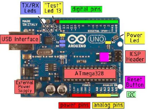
1. Arduino UNO
This is heart of the system consisting of microcontroller ATMEGA328 which controls all the peripherals and also executes the functions properly. Using arduino UNO programming I’m feeding the coding which is described later.
Fig 3 Arduino UNO Board
The Arduino Uno is a microcontroller board based on the ATmega328 (datasheet). It has 14 digital Input/output pins (of which 6 can be used as PWM outputs), 6 analog inputs, a 16 MHz crystal oscillator, a USB connection, a power jack, an ICSP header, and a reset button. It contains everything needed to support the microcontroller; simply connect it to a computer with a USB cable or power it with AC-to-DC adapter or battery to get started. The Uno differs from all preceding boards in that it does not use the FTDIUSB-to-serial driver chip. Instead, it features the Atmega8U2 programmed as a USB-to-serial converter.
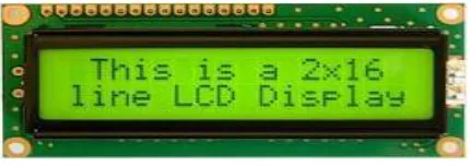
2. Liquid Crystal Display (LCD)
It is 16*2 LCD connected to the arduino board, LCD simply showing the modes which have been selected at the beginning according to the priority.An LCD consists of two glass panels, with the liquid crystal material sand witched in between them. The inner surface of the glass plates are coated with transparent electrodes which define the character, symbols or patterns to be displayed polymeric layers are present in between the electrodes and the liquid crystal, which makes the liquid crystal molecules to maintain a defined orientation angle. One each polarizer is pasted outside the two glass panels. These polarizer would rotate the light rays passing through them to a definite angle, in a particular direction. When the LCD is in the off state, light rays are rotated by the two polarizer and the liquid crystal, such that the light rays come out of the LCD without any orientation, and hence the LCD appears transparent. When sufficient voltage is applied to the electrodes, the liquid crystal molecules would be aligned in a specific direction. The light rays passing through the LCD would be rotated by the polarizer, which would result in activating or highlighting the desired characters.
The LCD’s are lightweight with only a few millimetres thickness. Since the LCD’s consume less power, they are compatible with low power electronic circuits, and can be powered for long durations. The LCD does don’t generate light and so light is needed to read the display. By using backlighting, reading is possible in the dark. The LCD’s have long life and a wide operating temperature range. Changing the display size or the layout size is relatively simple which makes the LCD’s more customer friendly.
Fig 4. Liquid Crystal Display
The LCD display consists of two lines, 20 characters per line that is interfaced with the PIC16F73.The protocol (handshaking) for the display is as shown in Fig. The display contains two internal byte-wide registers, one for commands (RS=0) and the second for characters to be displayed (RS=1). It also contains a user-programmed RAM area (the character RAM) that can be programmed to generate any desired character that can be formed using a dot matrix. To distinguish between these two data areas, the hex command byte 80 will be used to signify that the display RAM address 00h will be chosen Port1 is used to furnish the command or data type, and ports 3.2 to 3.4 furnish register select and read/write levels.
3. Relay
MODE LOAD ON LOAD OFF
MODE 1 L3,L4 L1,L2
MODE 2 L1,L2 L3,L4
MODE 3 L2,L4 L1,L3
MODE 4 L1,L3 L2,L4
A relay is usually an electromechanical device that is actuated by an electrical current. The current flowing in one circuit causes the opening or closing of another circuit. Relays are like remote-control switches and are used in many applications because of their relative simplicity, long life, and proven high reliability. Relays are used in a wide variety of applications throughout industry, such as in telephone exchanges, digital computers and automation systems. Highly sophisticated relays are utilized to protect electric power systems against trouble and power blackouts as well as to regulate and control the generation and distribution of power. In the home, relays are used in refrigerators, washing machines and dishwashers, and heating and air-conditioning controls. Although relays are generally associated with electrical circuitry, there are many other types, such as pneumatic and hydraulic. Input may be electrical and output directly mechanical, or vice versa. All relays contain a sensing unit, the electric coil, which is powered by AC or DC current. When the applied current or voltage exceeds a threshold value, the coil activates the armature, which operates either to close the open contacts or to open the closed contacts. When a power is supplied to the coil, it generates a magnetic force that actuates the switch mechanism. The magnetic force is, in effect, relaying the action from one circuit to another. The first circuit is called the control circuit and second is called as the load circuit.
Fig 5. Circuit Diagram of Relay
A type of relay that can handle the high power required to directly control and the main operation of a relay comes in places where only a low-power signal can be used to control a circuit. It is also used in places where only one signal can be used to control a lot of circuits. The high end applications of relays require high power to be driven by electric motors and so on. Such relays are called contactors.
On/Off Control: Example: Air conditioning control, used to limit and control a “high power load, such as a compressor
Limit Control: Example: Motor Speed Control, used to disconnect a motor if it runs slower or faster than the
desired speed
Logic Operation: Example: Test Equipment, used to connect the instrument to a number of testing points on the device under test.
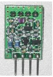
4. RF transmitter
This device is also connected to the UNO board. RF transmitter 433 MHz is used for the communication with the receiver. This transmitter section sending or accepting the commands which are related to the ON/OFF the required loads.
Fig 6. 315/434 MHz Ask Transmitter
The ST-TX01-ASK is an ASK Hybrid transmitter module. ST-TX01-ASK is designed by the Saw Resonator, with an effective low cost, small size, and simple-to-use for designing.
An RF transmitter module is a small PCB subassembly capable of transmitting a radio wave and modulating that wave to carry data. Transmitter modules are usually implemented alongside a microcontroller which will provide data to the module which can be transmitted. RF transmitters are usually subject to regulatory requirements which dictate the maximum allowable transmitter power output, harmonics, and band age requirements.
B. Receiver Section
In this system the wireless communication link is made possible between the RF remote and the control board with the help of RF communication. RF is ideal for effective and long distance wireless communication. The RF remote receives the commands from the PC through the serial communication link and is transmitted in to the air. Here the command denotes the on or off conditions of the home appliances. Each and every device connected to the power grid has its own separate command for the on and off conditions. The control board which is attached to the power grid control section in the home/industry consists of a RF receiver. This receives the commands transmitted by the transmitter and are given to the microcontroller.
1. RF Receiver
The ST-RX02-ASK is an ASK Hybrid receiver module. A effective low cost solution focusing at 315/433.92 MHZ.The circuit shape of ST-RX02-ASK is L/C.
Receiver Frequency: 315 / 433.92 MHz Typical sensitivity: -105dBm
Supply Current: 3.5mA IF Frequency: 1MHz.
Fig 7. 315/434 MHz Ask Receiver
An RF receiver module receives the modulated RF signal, and demodulates it. There are two types of RF receiver module: super heterodyne receiver and super-regenerative. Super regenerative modules are usually low cost and low power designs using a series of amplifiers to extract modulated data from a carrier wave. Super regenerative modules are generally impressed as there frequency of operation varies considerably with temperature and power supply voltage. Super heterodyne receivers have a performance advantage over super regenerative theory offer increase accuracy and stability over large voltage and temperature range. This stability comes from fixed crystal design which in turn leads to a comparatively more expensive product.
IV.EXPERIMENTAL RESULTS
The loads are interconnected and equally distributed. The maximum demand is predefined for a time window set by the user generally 15 minutes time slot is considered. As mentioned above once the LCD, Serial communication and current sensors are initialized the current sensors will continuously monitors the connected load and provide the proportionate voltages across the load. The power values for individual loads are calculated and the string of power values is sent to the serial port (V1I1, V2I2, V3I3, and V4I4). The MATLAB based software is programmed to be operated in the manual as well as automatic mode.
Manual Mode: The user can switch ON or OFF the loads without setting the maximum demand limit. The electrical parameters are being monitored on real time basis and displayed on the screen.
(a)
(b)
Figure shows the simulation result in manual mode of operation. The system is basically operated without maximum demand controller in this case. The various power values within the desired time span are plotted and the total power consumption for that particular period is as shown in the figure.
When mode 1 is selected and if auxiliary load over load above 150 W load 1 and load 2 turns off, When mode 2 is selected and if auxiliary load over load above 150 W load 3 and load 4 turns off, When mode 3 is selected and if auxiliary load over load above 150 W load 1 and load 3 turns off, When mode 4 is selected and if auxiliary load over load above 150 W load 2 and load 4 turns off, Over all wattage consumption is displayed on LCD connected to pin 8 to 13 of arduino uno board
V. CONCLUSION
The project implements the design of a system by which we can control the load through Pc remotely. Earlier such control over the load was operated manually. This system uses wireless transmission through transmitter and receiver connected at the power station and your pc or laptop respectively. Using this system, we can establish the link between RF remote and control board with the help of RF communication. The microcontroller plays a major role in receiving the command from RF receiver module and according to the priority; the load will be switched automatically.
REFERENCES
[1] R. Hooshmand, M Moazzami, “Optimum design of adaptive under frequency load shedding using artificial neural networks in isolated power system‖”. ELSEVIER, Electrical power and Energy systems 42(2012) 220-228.
[2] Divyansh Mathur, “Maximum Power Point Tracking with Artificial Neural Network”. International Journal of Emerging Science and Engineering (IJESE) ISSN: 2319– 6378, Volume-2, Issue-3, January 2014.
[3] C.T Hsu,M.S.Kang and C.S Chen “Design of adaptive load shedding by artificial neural networks”. IEE proc.- Gener. Transm. Distrib., Vol 152,No.3, May 2005.
[4] Testsuya Kakkonda, Eiichi Tsukada. “Electrical load forecasting by Neural Networks Considering Various Load Types”. IEEE Intelligent system ISAP 2003.
[5] Mohsen Hayati and Yazdan Shirvany . “ANN approach for short term load forecasting for Illam region‖”. IJECSE vol.1 number 2, 2007 ISSN1307-5179.
[6] M. Suman , M Venugopal, “ANN based short term hydrothermal scheduling”.‖ RECENT , vol 14,No 3(39) November 2013.
[7] Saxena Sachin Kumar, Singh Neha . “Load scheduling Algorithm prediction for multiple Tasks using Time series Neural Network”. IJARCSSE , Vol 3, Issue 5, May 2013, ISSN 2277 128X,
[8] M.A.Wazed , N. Nafis, M. T. Islam and A. S. M. Sayem Department of Engineering Design and Manufacture University of Malaya (UM), Faculty of Engineering 50603 Kuala Lumpur, Malaysia.
[9] Neelika Tripathi and Manju Vishwakarma- “AUTOMATIC POWER GRID CONTROLLER”,International Journal of Advanced Technology & Engineering Research (IJATER).
[10] Renfeng Chen; Ying Chen; Zhe Wang; Dept. of Electr. Eng. & Applic. of Electron. Technol., Tsinghua Univ., Beijing, China. [11] Garson W. Taylor. “Power system voltage stability”. New York: McGraw-Hill, 1994.
[12] Department of Mechanical and Intelligent System Engi- neering, Hokkaido University, Japan.