Volume 2009, Article ID 197682,10pages doi:10.1155/2009/197682
Research Article
Optimal Multiuser MIMO Linear Precoding with
LMMSE Receiver
Fang Shu, Wu Gang, and Li Shao-Qian
National Key Lab of Communication, University of Electronic Science and Technology of China, Chengdu 611731, China
Correspondence should be addressed to Fang Shu,[email protected]
Received 21 January 2009; Revised 11 May 2009; Accepted 19 June 2009
Recommended by Cornelius van Rensburg
The adoption of multiple antennas both at the transmitter and the receiver will explore additional spatial resources to provide substantial gain in system throughput with the spatial division multiple access (SDMA) technique. Optimal multiuser MIMO linear precoding is considered as a key issue in the area of multiuser MIMO research. The challenge in such multiuser system is designing the precoding vector to maximize the system capacity. An optimal multiuser MIMO linear precoding scheme with LMMSE detection based on particle swarm optimization is proposed in this paper. The proposed scheme aims to maximize the system capacity of multiuser MIMO system with linear precoding and linear detection. This paper explores a simplified function to solve the optimal problem. With the adoption of particle swarm optimization algorithm, the optimal linear precoding vector could be easily searched according to the simplified function. The proposed scheme provides significant performance improvement comparing to the multiuser MIMO linear precoding scheme based on channel block diagonalization method.
Copyright © 2009 Fang Shu et al. This is an open access article distributed under the Creative Commons Attribution License, which permits unrestricted use, distribution, and reproduction in any medium, provided the original work is properly cited.
1. Introduction
In recent years, with the increasing demand of transmit-ting high data rates, the (Multiple-Input Multiple-Output) MIMO technique, a potential method to achieve high capacity has attracted enormous interest [1, 2]. When multiple antennas are equipped at both base stations (BSs) and mobile stations (MSs), the space dimension can be exploited for scheduling multi-user transmission besides time and frequency dimension. Therefore, the traditional MIMO technique focused on point-to-point single-user MIMO (SU-MIMO) has been extended to the point-to-multipoint multi-user MIMO (MU-MIMO) technique [3,
4]. It has been shown that time division multiple access (TDMA) systems can not achieve sum rate capacity of MU-MIMO system of broadcast channel (BC) [5] while MU-MIMO with spatial division multiple access (SDMA) could, where one BS communicates with several MSs within the same time slot and the same frequency band [6, 7]. MU-MIMO based on SDMA improves system capacity taking advantage of user diversity and precanceling of multi-user interference at the transmitter.
transmitter to cancel the CCI at the transmitter. It is essential to have CSI at the BS since it allows joint processing of all users’ signals which results in a significant performance improvement and increased data rates.
The sum capacity in a multiuser MIMO broadcast channel is defined as the maximum aggregation of all the users’ data rates. For Gaussion MIMO broadcast channels (BCs), it was proven in [12] that Dirty Paper Coding (DPC) can achieve the capacity region. The optimal precoding of multi-user MIMO is based on dirty paper coding (DPC) theory with the nonlinear precoding method. DPC theory proves that when a transmitter has advance knowledge of the interference, it could design a code to compensate for it. It is developed by Costa which can eliminate the interference by iterative precoding at the transmitter and achieve the broadcast MIMO channel capacity [13, 14]. The famous Tomlinson-Harashima precoding (THP) is the non-linear precoding based on DPC theory. It is first developed by Tomlinson [15] and Miyakawa and Harashima [16] independently and then has become the Tomlinson-Harashima precoding (THP) [17–20] to combat the multi-user cochannel interference (CCI) with non-linear precod-ing. Although THP performs well in a multi-user MIMO scenario, deploying it in real-time systems is difficult because of its high complexity of the precoding at the transmitter. Many suboptimal MU-MIMO linear precoding techniques have emerged recently, such as the channel inversion method [21] and the block diagonalization (BD) method [22–24]. Channel inversion method [25] employs some traditional MIMO detection criterions, such as the Zero Forcing (ZF) and Minimum Mean Squared Error (MMSE), precoding at the transmitter to suppress the CCI Channel inversion method based on ZF can suppress CCI completely; however it may lead to noise amplification since the precoding vectors are not normalized. Channel inversion method based on MMSE compromises the noise and the CCI, and outperforms ZF algorithm, but it still cannot obtain good performance. BD method decomposes a multi-user MIMO channel into multiple single user MIMO channels in parallel to completely cancel the CCI by making use of the null space. With BD, each users precoding matrix lies in the null space of all other users channels, and the CCI could be completely canceled. The generated null space vectors are normalized vectors, which could avoid the noise amplification problem efficiently. So BD method performs much better than channel inversion method. However, since BD method just aims to cancel the CCI and suppress the noise, its precoding gain is not optimized.
It is obvious that the CCI, the noise, and the precod-ing gain are the factors affecting on the performance of the preprocessing MU-MIMO. The above linear precoding methods just take one factor into account without entirely consideration. A rate maximization linear precoding method is proposed in [26]. This method aims to maximize the sum rate of the MU-MIMO system with linear preprocessing. However, the optimized function in [26] is too complex to compute. In this paper, we solve the optimal linear precoding with linear MMSE receiver problem in a more simplified way.
H4
H3
H1
H2 MS4
MS3
MS1 MS2 BS
Figure1: The configuration of MU-MIMO system
An optimal MU-MIMO linear precoding scheme with linear MMSE receiver based on particle swarm optimization (PSO) is proposed in this paper. PSO algorithm has been used in many complex optimization tasks, especially in solving the optimization of continuous space [27,28]. In this paper, PSO is firstly introduced into MIMO research to solve some optimization issues. The adoption of PSO to MIMO system provides a new method to solve the MIMO processing problem. In this paper, we first analyze the optimal linear precoding vector with linear MMSE receiver and establish a simplified function to measure the optimal linear precoding problem. Then, we employ the novel PSO algorithm to search the optimal linear precoding vector according to the simplified function. The proposed scheme obtains significant MU-MIMO system capacity and outperforms the channel block diagonalization method.
This paper is organized into seven parts. The system model of MU-MIMO is given inSection 2. Then the analysis of optimal linear precoding with linear MMSE receiver is given in Section 3. The particle swarm optimization algorithm is given inSection 4. InSection 5, the proposed optimal linear precoding MU-MIMO scheme with LMMSE detection based on particle swarm optimization is intro-duced. InSection 6, the simulation results and comparisons are given. Conclusions are drawn in the last section. The channel block diagonalization algorithm is given in the appendix.
2. System Model of MU-MIMO
The MU-MIMO system could transmit data streams of multiple users of the same cellular at the same time and the same frequency resources asFigure 1shows.
We consider an MU-MIMO system with one BS andK
MS, where the BS is equipped withM antennas and each MS with N antennas, as shown inFigure 2. The point-to multipoint MU-MIMO system is employed in downlink transmission.
Because MU-MIMO aims to transmit data streams of multiple-users at the same time and frequency resources, we discuss the algorithm at single-carrier, for each subcarrier of the multicarrier system, and it is processed as same as the single-carrier case. Since OFDM technique deals the frequency selective fading as flat fading, we model the channel as the flat fading MIMO channel:
Hk= ⎡ ⎢ ⎢ ⎢ ⎣
h1,1 · · · h1,M
..
. . .. ...
hN,1 · · · hN,M ⎤ ⎥ ⎥ ⎥
S1
S1
SK
T1
T2
TK .
. .
. . . 1
M
H1
HK 1
N
1
N
1
N Y1
Y2
YK
G1
G2
Gk
s1
s2
sk
Figure2: The block diagram of MU-MIMO system
whereHkis the MIMO channel matrix of userk.hi,jindicates
the channel impulse response coupling the jth transmit antenna to the ith receive antenna. Its amplitude obeys independent and identically Rayleigh-distribution.
Data streams ofK (K ≤M) users are precoded by their precoding vectorsTk(k=1· · ·K) before transmission.Tk
is theM×1 normalized precoding vector for user kwith
THkTk=1. The received signal at thekth user is
yk=HkTk pksk+Hk K
i=1,i /=k
Ti pisi+nk
K
k=1
pk=p0
(2)
where yk is the received signal of user k. The elements
of additive noise nk obey distribution CN(0,N0) that are
spatially and temporarily white. pk is the transmit signal
power of thekth data stream, and p0 is the total transmit
power.
The received signal at thekth user can also be expressed as
yk=HkWs+nk
W=[T1 T2 · · · TK]
s= p1s1 p2s2 · · · pKsK
T
(3)
wheresis the transmitted symbol vector withKdata streams,
Wis the precoding matrix withKprecoding vectors, and [·]T denotes the matrix transposition:
Hk=HkW (4)
The channel matrixHkcan be assumed as the virtual channel
matrix of user k after precoding. At the receiver, a linear receiverGkis exploited to detect the transmit signal for the
userk. The detected signal of thekth user is
sk=Gkyk. (5)
The linear receiver Gk can be designed by ZF or MMSE
criteria, and linear MMSE will obtain better performance.
In order to simplify the analysis, the power allocation is assumed as equalβ = pk/N0 = p0/KN0, and linear MMSE
MIMO detection is used in this paper as
Gk=hHk
HkHHk +βIN −1
, (6)
where (·)−1indicates the inverse of the matrix, (·)Hdenotes the matrix conjugation transposition, andIN is theN×N
identity matrix:
hk=HkTk=
Hk
k=[HkW]k, (7)
where [·]kdenotes thekth column of the matrix. Then the
detected SINR for the userkwith the linear detection is
SINRk=
βGkHkTk 2
K
i=1,i /=kβGkHkTi 2
+Gk 2
2
= β
G kHkTk
2
/Gk 2
2 K
i=1,i /=kβGkHkTi 2
/Gk 2
2+ 1
, (8)
where · 2denotes the matrix two-norm.
Because the nonnormalized precoding vector will amp-lify the noise at the receiver, the precoding vectors Tk are
assumed to be normalized as follow:
Tk2=1 (9)
fork=1,. . .,K.
3. Optimal Multiuser MIMO Linear Precoding
We assume that the MIMO channel matrices Hk(k =
1,. . .,K) are available at the BS. It can be achieved either by channel reciprocity characteristics in time-division-duplex (TDD) mode or by feedback in frequency-division-duplex (FDD) mode. And the channel matrixHk is known at the
receiverk through channel estimation. We just discuss the equal power allocation case in this paper. The optimal power allocation is achieved through water-filling according to the SINR of each user.
The MIMO channel of userkcan be decomposed by the singular value decomposition (SVD) as
Hk=UkΣkVHk. (10)
If we applyTk = [Vk]1to precode for userk, it obtains
the maximal precoding gain as follow.
Lemma 1. One has
HkTk2=Hk[Vk]12=λmaxk , (11)
where[Vk]1denotes the first column ofVk,andλmaxk denotes
Proof. One has
Thus, precoding with the singular vector corresponding to the maximal singular value is an initial thought to obtain good performance. However, if the singular vector is directly used at the transmitter as the precoding vector, the CCI will be large, and the performance will be degraded severely. Only for the special case that the MIMO channel among all these users are orthogonal that the CCI will be zero if we directly use the singular vector of each user as its precoding vector. But in realistic case, the transmit users’ channels are always nonorthogonal, and so the singular vector could not be utilized directly. We have drawn some analysis as follow.
(1)Ideal channel case.The ideal channel case is that the MIMO channels of transmitting users’ are orthogonal. There is
([Vk]1)H[Vi]1=0 (i /=k) (14)
If we applyTk=[Vk]1to precode for userk, the maximal
precoding gain will be obtained as (13) shows, and the CCI will turn to zero as follow.
Lemma 2. One has
K
After linear MMSE detection at the receiver, user k obtains the maximal SINR as follows.
Lemma 3. One has
Proof. One has
(2)Ill channel caseThe ill channel case is that all these transmitting users’ channels are highly correlated. There is
([Vk]1)H[Vi]1=1 (i /=k). (29)
If we still applyTk = [Vk]1 to precode for userk, the
multiuser CCI will be very large, and the system performance will be degraded severely. The SINR after MMSE detection with equal power allocation for userkis as follows.
Lemma 4. One has
SINRk=
whereλkindicates the first diagonal element of the diagonal
matrixΣk. So there is
(3)Practical case.The practical case is that the transmit-ting users’ channels are neither orthogonal nor ill. There is
([Vk]1)H[Vi]1=/ 0 (i /=k)
([Vk]1)H[Vi]1=/1 (i /=k).
(39)
0.1 0.2 0.3 0.4 0.5 0.6 0.7 0.8 0.9 1
CDF
0 5 10 15
Capacity (bps/Hz)
Channel inversion with ZF precoder, 42R 4 data streams Channel inversion with MMSE, precoder, 4T2R 4 data streams Proposed MU-MIMO 4T2R4 data streams
Figure3: The system capacity CDF comparison of the two schemes.
ξk = |THk[Vk]1|can be the parameter to measure the
precoding gain, andρi= |THk[Vi]1|can be the parameter to
measure the CCI. The SINR for userkaccording to the above analysis can be approximated denoted as
SINRk≈
βλmax k ξk
2
K i /=k,i=1β
λmax k ρi
2
+ 1
=
λmaxk (THk[Vk]1) 2
K
i /=k,i=1λmaxk (THk[Vi]1) 2
+ 1/β .
(40)
The system capacity is related to SINR of the transmit users k, (k = 1,. . .,K). So in order to obtain the system capacity, we should obtain the SINRk. Thus, when the
optimal precoding vector is obtained by the PSO algorithm, the system capacity could be calculated by (41).
The system capacity of the MU-MIMO system can be indicated as
CMU= K
k=1
log2(1 + SINRk). (41)
We aim to maximize the system capacity of the MU-MIMO system in this paper. The optimal MU-MU-MIMO linear precoding vector for the MU-MIMO system is the vector that can maximize the SINR at each receiver as
Tk=arg max Tk∈U
K
k=1
log2
⎛ ⎜ ⎝1 +
λmax
k (THk[Vk]1) 2
K
i /=k,i=1λmaxk (THk[Vi]1) 2
+ 1/β
⎞ ⎟ ⎠
(42)
where Udenotes the unitary vector that UHU = I. From
the above equation, it is clear that if we want to maximize
the system capacity of MU-MIMO, then the SINR of each user should be maximized. The SINR of userkis associated with three parameters as the singular vector correspond to the maximal singular value of all users and the noise.
4. The Particle Swarm Optimization Algorithm
Particle swarm optimization algorithm was originally pro-posed by Kennedy and Eberhart[27] in 1995. It searches the optimal problem solution through cooperation and competition among the individuals of population.
Imagine a swarm of bees in a field. Their goal is to find in the field the location with the highest density of flowers. Without any prior knowledge of the field, the bees begin in random locations with random velocities looking for flowers. Each bee can remember the location that is found the most flowers and somehow knows the locations where the other bees found an abundance of flowers. Torn between returning to the location where it had personally found the most flowers, or exploring the location reported by others to have the most flowers, the ambivalent bee accelerates in both directions to fly somewhere between the two points. There is a function or method to evaluate the goodness of a position as the fitness function. Along the way, a bee might find a place with a higher concentration of flowers than it had found previously. Constantly, they are checking the concentration of flowers and hoping to find out the absolute highest concentration of flowers.
Suppose that the size of swarm and the dimension of search space areCandD,respectively. Each individual in the swarm is referred to as a particle. The location and velocity of particle i(i = 1,. . .,C) are represented as the vector
xi =[xi1,xi1,. . .,xiD]T andvi=[vi1,vi2,. . .,viD]T. Each bee
remembers the location where it personally encountered the most flowers which is denoted asPi = [pi1,pi2,. . .,piD]T,
which is the flight experience of the particle itself. The highest concentration of flowers discovered by the entire swarm is denoted asPg =[pg1,pg2,. . .,pgD]T, which is the
flight experience of all particles. Each particle is searching for the best location according toPiandPg. The particlei
updates its location and velocity according to the following two formulas [27]:
vt+1id =wvidt +c1ϕ1
pidt −xidt
+c2ϕ2
ptgd−xidt
xt+1id =xtid+vidt+1
(43)
where t is the current iteration number; vidt and xtid + 1
denote the velocity and location of the particleiin thedth dimensional direction. pidt is the individual best location
of particle i in the dth dimensional direction, ptgd is the
population best location in thedth dimensional direction.ϕ1
andϕ2are the random numbers between 0 and 1,c1andc2
are the learning factors, andwis the inertia factor. Learning factors determine the relative “pull” ofPtiandPtgthat usually
contentc1=c2=2. Inertia factor determines to what extent
the particle remains along its original course unaffected by the pull ofPt
g andPti that is usually between 0 and 1. After
process is repeated until reaching the maximal iteration or the termination criteria are met.
5. The Optimal Linear Precoding
Multiuser MIMO with LMMSE Detection
Based on Particle Swarm Optimization
With the adoption of PSO algorithm and the simplified function (40), the optimal linear precoding vectorTk (k =
1,. . .,K) could be easily searched.
The proposed optimal MU-MIMO linear precoding scheme based on PSO algorithm will search the optimal precoding vector for each user following 6 steps.
(1) The BS obtainsλmaxk , [Vk]1andβof each user.
(2) The BS employs the PSO algorithm to search the optimal linear precoding vector for each user. For userk, the PSO algorithm sets the maximal iteration number I and a group of M dimensional particles with the initial velocityv1
i,k = [vi1,k1 ,vi2,k1 ,. . .,v1iM,k] T
and the initial locationx1
i,k = [xi1,k1 ,x1i2,k,. . .,x1iM,k] T
for particle i(i = 1,. . .,C). In order to accelerate the searching process, the initial locationx1i,kcould be initialized as [Vk]1, while the initial velocityv1i,kcould
be produced randomly. The real and imaginary parts of the initial velocity obey a normal distribution with mean zero and standard deviation one.
(3) The BS begins to search with the initial locationx1i,k
and velocity v1i,k. The goodness of the location is measured by the following equation:
fi,kt =
λmaxk [(xti,k) H
[Vk]1] 2
K
j=1,j /=kλmaxk [(xti,k) H
[Vj]1] 2
+ 1/β
, (44)
where the fitness function fi,kt indicates the obtained
SINR for userkprecoded byxti,k. The PSO algorithm findsPt
i,k andPtg,k that are individual best location
and population best location measured by (44) for the next iteration. Pti,k denotes the individual best location which means the best location of particle
i at the tth iteration of the kth user. Ptg,k denotes the population best location which means the best location of all particles at thetth iteration of thekth user.
(4) For thetth iteration, the algorithm finds aPti,kand a
Ptg,k. The location and velocity for each particle will be updated according to (43) for the next iteration. In order to obtain the normalized optimal precoding vector to suppress the noise, the locationxt
i,k should
be normalized in each iteration.
(5) When reaching the maximal iteration numberI, the algorithm stops, and PI
g,k is the obtained optimal
precoding vector for userk.
(6) For an MU-MIMO system withKusers, the scheme will search the precoding vectors according to the above criteria for each user.
0.1 0.2 0.3 0.4 0.5 0.6 0.7 0.8 0.9 1
CDF
0 2 4 6 8 10 12 14 16 18
Capacity (bps/Hz) Coordinate Tx-Rx BD 4T2R 4 users Proposed MU-MI MO 4T2R 4 users
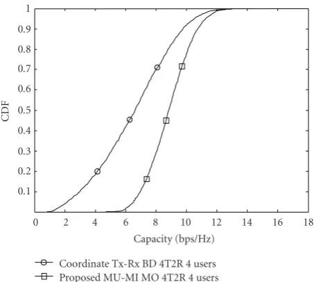
Figure4: The system capacity CDF comparison of the two schemes.
6. Simulation Results
We simulated the proposed MU-MIMO scheme, the BD algorithm in [22] (Coordinate Tx-Rx BD), and the channel inversion algorithm in [25] in this paper to compare their performance under the same simulation environment.
Figure 3is the system capacity comparison of the cumu-lative distribution function (CDF) of the channel inversion algorithm with ZF precoder and MMSE precoder and the proposed MU-MIMO algorithm when M = 4,N = 2,
p0/N0 = 5dBwith equation power allocation and MMSE
detection at the receiver. For channel inversion method, the BS transmits 4 date streams and 2 users simultaneously with 2 date stream for each user. For the proposed MU-MIMO, the BS transmit 4 data streams and 4 users simultaneously with 1 data stream for each user.
Figure 4is the system capacity comparison of the CDF of the coordinated Tx-Rx BD algorithm and the proposed MU-MIMO algorithm whenM = 4, K = 4, N = 2, p0/N0 =
5dBwith equation power allocation and MMSE detection at the receiver.
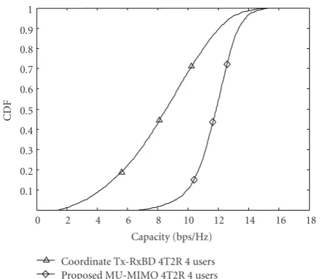
Figure 5is the system capacity comparison of the CDF of the coordinated Tx-Rx BD algorithm and the proposed MU-MIMO algorithm whenM = 4, K = 4, N = 4, p0/N0 =
5dBwith equation power allocation and MMSE detection at the receiver. Both the simulation results of the proposed MU-MIMO scheme with PSO algorithm fromFigure 3toFigure 5
are based on the PSO parameters with the particle number
C=20 and the iteration numberI=20. It could be seen that the proposed MU-MIMO scheme can effectively increase the system capacity compared to the BD algorithm and channel inversion algorithm.
0.1 0.2 0.3 0.4 0.5 0.6 0.7 0.8 0.9 1
CDF
0 2 4 6 8 10 12 14 16 18
Capacity (bps/Hz) Coordinate Tx-RxBD 4T2R 4 users Proposed MU-MIMO 4T2R 4 users
Figure5: The system capacity CDF comparison of the two schemes.
10−3 10−2 10−1 100
BER
0 1 2 3 4 5 6 7 8 9 10
SNR (dB) Coordinate Tx-RxBD 4T2R 4 users Proposed MU-MIMO 4T2R 4 users
Figure6: The BER comparison of the two schemes.
Both the schemes adopt equal power allocation, MMSE detection, QPSK, and no channel coding. The proposed MU-MIMO scheme, with PSO algorithm from Figures6and7
are based on the PSO parameters with the particle number
C=20 and the iteration numberI=20.
From the simulation results, it is clear that the proposed MU-MIMO linear precoding with LMMSE detection based on particle swarm optimization scheme outperforms the BD algorithm and the channel inversion algorithm. The reason lies in that the BD algorithm just aims to utilize the normalized precoding vector to cancel the CCI and suppress the noise. The channel inversion algorithm also aims to suppress CCI and noise. So the users’ transmit signal covariance matrices of these schemes are generally not
10−3 10−2 10−1 100
BER
0 1 2 3 4 5 6 7 8 9 10
SNR (dB) Coordinate Tx-RxBD 4T2R 4 users Proposed MU-MIMO 4T2R 4 users
Figure7: The BER comparison of the two schemes.
10−3 10−2 10−1
BER
0 1 2 3 4 5 6 7 8 9 10
SNR (dB)
Proposed MU-MIMO 4T4R,C=20,I=30 Proposed MU-MIMO 4T4R,C=20,I=20 Proposed MU-MIMO 4T4R,C=20,I=10 Proposed MU-MIMO 4T4R,C=20,I=5
Figure8: The BER comparison of the two schemes with differentC
andI.
optimal that are caused by the inferior precoding gain. The proposed MU-MIMO optimal linear precoding scheme aims to find the optimal precoding vector to maximize each users’ SINR at each receiver to improve the total system capacity.
larger than 20 for this case, the algorithm could not obtain more performance gain. Generally, for different case, the best iteration number is different. The iteration number is related to the transmit antenna numberMat the BS and the transmit user numberK (K≤M).With the increasing ofMorK, the iteration number should increase in order to obtain the best performance.
7. Conclusion
This paper solves the optimal linear precoding problem with LMMSE detection for MU-MIMO system in downlink transmission. A simplified optimal function is proposed and proved to maximize the system capacity. With the adoption of the particle swarm optimization algorithm, the optimal linear precoding vector with LMMSE detection for each user could be searched. The proposed scheme can obtain significant system capacity improvement compared to the multi-user MIMO scheme based on channel block digonolization under the same simulation environment.
Appendix
Coordinated Tx-Rx BD Algorithm
Coordinated Tx-Rx BD algorithm is the improved BD algorithm. It could solve the antenna constraint problem in traditional BD algorithm and extends the BD algorithm to arbitrary antenna configuration. For a coordinated Tx-Rx BD algorithm with M transmit antennas at the BS, N
receive antennas at the MS, andK users to be transmitted simultaneously, the algorithm follows 6 steps.
(1) For j=1,. . .,K, compute the SVD
Hj=UjΣjVHj. (A.1)
(2) Determinemj, which is the number of subchannels
for each user. In order to compare the two schemes fairly,mj=1 for each user.
(3) For j=1,. . .,K, letAjbe the firstmjcolumns ofUj.
CalculateHj=AHjHj.
Hj=
HT1 · · · H
T j−1 H
T
j+1 · · · H
T K
T
(A.2)
(4) For j = 1,. . .,K, computeV(0)j , the right null space ofHjas
Hj=UjΣj
V(1)j V
(0) j
H
, (A.3)
whereV(1)j holds the firstLjright singular vectors,V(0)j holds
the lastN−Ljright singular vectors andLj=rank(Hj).
(5) Compute the SVD
HjV(0)j =Uj ⎡ ⎣Σj 0
0 0
⎤
⎦V(1)j V(0)j H. (A.4)
(6) The precoding matrixWfor the transmit users with average power allocation is
W=V(0)1 V(1)1 V(0)2 V(1)2 · · · V(0)K V(1)K
. (A.5)
Acknowledgments
The project was supported by the National Natural Science Foundation of China (60702073) and the Key Laboratory of Universal Wireless Communications Lab. (Beijing University of Posts and Telecommunications), Ministry of Education, China.
References
[1] G. J. Foschini and M. J. Gans, “On limits of wireless com-munications in a fading environment when using multiple antennas,”Wireless Personal Communications, vol. 6, no. 3, pp. 311–335, 1998.
[2] A. Goldsmith, S. A. Jafar, N. Jindal, and S. Vishwanath, “Capacity limits of MIMO channels,”IEEE Journal on Selected Areas in Communications, vol. 21, no. 5, pp. 684–702, 2003. [3] Q. H. Spencer, C. B. Peel, A. L. Swindlehurst, and M. Haardt,
“An introduction to the multi-user MIMO downlink,”IEEE Communications Magazine, vol. 42, no. 10, pp. 60–67, 2004. [4] C. Windpassinger, R. F. H. Fischer, T. Vencel, and J. B. Huber,
“Precoding in multiantenna and multiuser communications,”
IEEE Transactions on Wireless Communications, vol. 3, no. 4, pp. 1305–1316, 2004.
[5] N. Jindal and A. Goldsmith, “Dirty-paper coding versus TDMA for MIMO broadcast channels,”IEEE Transactions on Information Theory, vol. 51, no. 5, pp. 1783–1794, 2005. [6] P. Viswanath and D. N. C. Tse, “Sum capacity of the vector
Gaussian broadcast channel and uplink-downlink duality,”
IEEE Transactions on Information Theory, vol. 49, no. 8, pp. 1912–1921, 2003.
[7] S. Vishwanath, N. Jindal, and A. Goldsmith, “Duality, achievable rates, and sum-rate capacity of Gaussian MIMO broadcast channels,”IEEE Transactions on Information Theory, vol. 49, no. 10, pp. 2658–2668, 2003.
[8] E. A. Jorswieck and A. Sezgin, “Impact of spatial correlation on the performance of orthogonal space-time block codes,”IEEE Communications Letters, vol. 8, no. 1, pp. 21–23, 2004. [9] S. N. Diggavi, “On achievable performance of spatial diversity
fading channels,” IEEE Transactions on Information Theory, vol. 47, no. 1, pp. 308–325, 2001.
[10] P. Tarasak, H. Minn, and V. K. Bhargava, “Linear prediction receiver for differential space-time block codes with spatial correlation,”IEEE Communications Letters, vol. 7, no. 11, pp. 543–545, 2003.
[11] H. B¨olcskei, D. Gesbert, and A. J. Paulraj, “On the capacity of OFDM-based spatial multiplexing systems,”IEEE Transactions on Communications, vol. 50, no. 2, pp. 225–234, 2002. [12] M. H. M. Costa, “Writing on dirty paper,”IEEE Transactions
[13] H. Weingarten, Y. Steinberg, and S. Shamai (Shitz), “The capacity region of the Gaussian MIMO broadcast channel,” in
Proceedings of IEEE International Symposium on Information Theory, p. 174, June 2004.
[14] G. Caire and S. Shamai, “On the achievable throughput of a multiantenna Gaussian broadcast channel,”IEEE Transactions on Information Theory, vol. 49, no. 7, pp. 1691–1706, 2003. [15] M. Tomlinson, “New automatic equaliser employing modulo
arithmetic,”Electronics Letters, vol. 7, no. 5-6, pp. 138–139, 1971.
[16] H. Miyakawa and H. Harashima, “Matched-transmission techniuqe for channels with intersymbol interference,”IEEE Transactions on Communications, vol. 20, pp. 774–779, 1972. [17] V. Stankovic and M. Haardt, “Successive optimization
Tomlinson-Harashima precoding (SO THP) for multi-user MIMO systems,” inProceedings of IEEE International Confer-ence on Acoustics, Speech and Signal Processing (ICASSP ’05), vol. 3, pp. 1117–1120, March 2005.
[18] W. Miao, L. Xiao, Y. Li, S. Zhou, and J. Wang, “Joint stream-wise THP transceiver disign for the multiuser MIMO downlink,” inProceedings of IEEE Wireless Communications & Networking Conference (WCNC ’08), pp. 330–334, 2008. [19] K. Takeda, H. Tomeba, and F. Adachi, “BER performance
of joint THP/pre-DFE,” in Proceedings of IEEE Vehicular Technology Conference (VTC ’08), pp. 1016–1020, 2008. [20] P. L. Athanasios, “Tomlinson-Harashima precoding with
partial channel knowlegde,”IEEE Transactions on Communi-cations, vol. 53, no. 1, pp. 5–9, 2005.
[21] T. Haustein, C. von Helmolt, E. Jorswieck, V. Jungnickel, and V. Pohl, “Performance of MIMO systems with channel inversion,” inProceedings of the 55th IEEE Vehicular Technology Conference (VTC ’02), vol. 1, pp. 35–39, 2002.
[22] Q. H. Spencer, A. L. Swindlehurst, and M. Haardt, “Zero-forcing methods for downlink spatial multiplexing in mul-tiuser MIMO channels,”IEEE Transactions on Signal Process-ing, vol. 52, no. 2, pp. 461–471, 2004.
[23] L.-U. Choi and R. D. Murch, “A transmit preprocessing tech-nique for multiuser MIMO systems using a decomposition approach,” IEEE Transactions on Wireless Communications, vol. 3, no. 1, pp. 20–24, 2004.
[24] K.-K. Wong, R. D. Murch, and K. B. Letaief, “A joint-channel diagonalization for multiuser MIMO antenna systems,”IEEE Transactions on Wireless Communications, vol. 2, no. 4, pp. 773–786, 2003.
[25] C. B. Peel, B. M. Hochwald, and A. L. Swindlehurst, “A vector-perturbation technique for near-capacity multiantenna multiuser communication—part I: channel inversion and regularization,”IEEE Transactions on Communications, vol. 53, no. 1, pp. 195–202, 2005.
[26] M. Stojnic, H. Vikalo, and B. Hassibi, “Rate maximization in multi-antenna broadcast channels with linear preprocessing,” inProceedings of IEEE Global Telecommunications Conference (GLOBECOM ’04), vol. 6, pp. 3957–3961, November 2004. [27] J. Kennedy and R. C. Eberhart, “Particle swarm optimization,”
in Proceedings of IEEE International Conference on Neural Networks, vol. 5, pp. 1942–1948, 1995.