R E S E A R C H
Open Access
A low-complexity 3D massive MIMO
scheme jointly using statistical and
instantaneous CSIT
Lixing Fan
1,2, Shiwen He
1,2, Yongming Huang
1,2and Luxi Yang
1,2*Abstract
In this paper, we propose a three-dimensional (3D) beamforming scheme for the massive multiple-input
multiple-output (MIMO) system where the base station (BS) employs a uniform rectangular array (URA). In order to avoid the high computational complexity involving large-dimensional channel matrices, a two-stage beamforming method is applied where the second-stage beamforming is a Kronecker product of azimuth and elevation discrete Fourier transform (DFT) beamforming. These DFT prebeamformers are used for cell splitting and form effective channels with lower dimension for first-stage precoding. We develop a low-complexity user grouping algorithm based on the statistical channel state information at the transmitter (CSIT) to partition users. Each group of users is served by the signal-to-leakage-and-noise ratio (SLNR) precoding aiming at suppressing the intra-group and adjacent-group interferences, which is a good balance between performance and complexity. We derive the
approximate signal-to-interference-plus-noise ratio (SINR) of our proposed scheme. Numerical results validate that the SINR approximations are tight and indicate the significance of the proposed 3D beamforming scheme.
Keywords: Massive MIMO, 3D MIMO, Deterministic equivalent
1 Introduction
In order to meet the demand of explosively increasing data services, the massive multiple-input multiple-output (MIMO) system has emerged as a promising technology for the next generation of cellular systems [1–3]. The basic premise behind massive MIMO is to reap all the bene-fits of conventional MIMO on a much greater scale, by deploying a few hundred antennas at the base station (BS) to serve a multiplicity of users simultaneously in the same time-frequency resource [4–7]. However, in practice, it is infeasible to place a large number of antennas only in the azimuth direction at the BS. To cope with this limita-tion, three-dimensional (3D) MIMO has been introduced, where antennas are deployed in a two-dimensional (2D) grid at the BS to enable the multiplexing of many users in a multi-user MIMO (MU-MIMO) fashion [8–12].
*Correspondence: [email protected]
1School of Information Science and Engineering, Southeast University, 2 Sipailou, 210096 Nanjing, People’s Republic of China
2Key Laboratory of Underwater Acoustic Signal Processing of Ministry of Education, Southeast University, Nanjing 210096, China
In 3D MIMO, elevation antennas are exploited to design 3D beamforming. More users can thus be served by the 3D beamformer with the same azimuth but different ele-vation angles [13]. A practical method for performing per-user adaptation of the elevation direction is presented in [14], which is transparent to the Long-Term Evolution (LTE) standard and requires no changes to the exist-ing mobiles. But no performance analysis is given. The achievable sum rate is analyzed for uplink 3D MIMO systems with zero-forcing (ZF) receivers in [15, 16]. In [17], 3D beamforming is developed which consists of azimuth two-stage beamforming and one elevation pre-beamformer. This scheme takes advantage of cell split-ting by prebeamformers and functions efficiently when users in the same group have identical angle of arrival (AoA) intervals but have nonoverlapping AoA intervals in the different groups. However, users are usually ran-domly distributed and the angle requirements cannot be guaranteed. Besides, elevation groups are designated by orthogonal time-frequency slots to assure near orthogo-nality, which does not exploit the full use of resources.
And the specific user grouping algorithm for 3D massive MIMO is not developed.
In this paper, a low-complexity 3D beamforming scheme is proposed for the massive MIMO system where the BS deploys a uniform rectangular array (URA). We apply two-stage beamforming to avoid the high com-plexity involving the large-dimensional channel matrices. The second-stage beamforming is a Kronecker product of azimuth and elevation discrete Fourier transform (DFT) prebeamformers, since the 3D channel covariance can be approximated by a Kronecker product of azimuth and elevation correlations and it is possible to separate the 3D channel into azimuth and elevation directions which are respectively served by uniform linear arrays (ULAs) in associated directions at the BS [18]. Considering the one-ring scattering model, the azimuth and elevation correlations are characterized by Toeplitz matrices, and the eigenvector matrices of these Toeplitz matrices are approximated by submatrices of DFT matrix when the number of antennas is large [19, 20]. So, we apply the DFT beamforming as the azimuth and elevation prebeam-formers, and their Kronecker product constructs the 3D prebeamformer. These DFT prebeamformers are used for cell splitting, and all groups are all working in the same time-frequency resource. We develop a low-complexity user grouping algorithm to partition users into groups using statistical channel state information at the transmit-ter (CSIT).
The first-stage precoding is designed based on the effective channels formed by large-dimensional instanta-neous channels and DFT prebeamformers, which has low complexity. We employ the signal-to-leakage-and-noise ratio (SLNR) precoding considering the intra-group and adjacent-group interferences which dominate the inter-group interferences. The SLNR precoding is designed based on the signal-to-leakage-and-noise ratio as the opti-mization metric, where leakage is a measure which quan-tifies the interference power caused by the desired user on the signal received by others [21]. It is a good bal-ance between eliminating co-channel interference (CCI) and noise, while zero forcing (ZF) design considers the CCI only and suffers from noise enhancement. Moreover, the ZF precoding imposes a restriction on the number of antennas, while for SLNR precoding there is no require-ment on the relation between the number of transmit and receive antennas. Compared to the signal-to-interference-plus-noise ratio (SINR) precoding which is obtained iter-atively due to the coupled optimization problem [22], the SLNR precoding admits a closed-form solution, since the SLNR metric results in a decoupled optimization prob-lem. However, the SLNR precoding aims at maximizing SLNR instead of SINR, so it leads to suboptimal per-formance. In terms of complexity, the SLNR precoding involves matrix inversion which has high complexity with
large-dimensional channel matrix in massive MIMO sys-tems. In this paper, we partition the cell and group users, so the effective number of BS antennas for each group becomes small, and the requirement on the antenna num-ber of ZF precoding may not be satisfied. Thus, we apply the SLNR precoding. Furthermore, the matrix inversion does not cause high complexity because of the lower dimensional effective channels.
We derive the approximate SINR for our proposal using deterministic equivalents [3, 23–26]. This method based on the random matrix theory enables us to approximate the stochastic SINR with deterministic expression which is dependent only on statistical channel state information (CSI). Numerical results show that the SINR approxi-mations are tight when the number of BS antennas is large and validate the effectiveness of the proposed low-complexity user grouping algorithm. The proposed SLNR precoding is illustrated to be a good balance between performance and complexity.
The rest of this paper is organized as follows. We present the system model in Section 2. In Section 3, we intro-duce the proposed 3D beamforming scheme. We derive the approximate SINR of our proposal in Section 4. The numerical results are shown in Section 5, and the paper is concluded in Section 6.
Notation:We use boldface capital letter Xfor matrix, boldface small letter xfor vector, and small letter xfor scalar. XH denotes the Hermitian transpose of X; tr(X) denotes the trace ofX.X⊗Ydenotes the Kronecker prod-uct ofXandY.X[:,(x1:x2)] denotes a matrix formed by
thex1tox2columns ofX. The identity matrix with rankb
is denoted byIb.
2 System model
Consider a single-cell downlink massive MIMO system in
Fig. 1. The BS is equipped with anN ×M URA where
M,N 1. The large URA can become an integral part
of a large infrastructure, deployed along walls of a shop-ping mall or facade of a building [27]. In our paper, we assume that the BS antennas are mounted on the top of a building [28] and seldom obstructed by local scatter.K
single-antenna users are located on the street level and surrounded by scatters. They are all served simultane-ously in the same time-frequency resource.
2.1 3D channel model
Fig. 1A single-cell 3D massive MIMO system where the BS employs a URA
with physical channel parameters [30, 31]. But this method is not suitable for the performance analysis. The other one is a non-parametric approach where the spa-tial correlation is reproduced using theoretical spaspa-tial correlations [11, 12, 17].
In this paper, we consider the correlated channel model [3, 32] which is given by
hk =β
for thekth user, wherewkis a complex circularly
symmet-ric Gaussian vector with mean0and covariance matrix
IMN, i.e.,wk ∈ CMN ∼ CN(0,IMN), andβkdenotes the path loss, which is
βk= 1
rkγ, (2)
whererkis the distance between thekth user and the foot of BS,γ is the decay exponent, andRk ∈CMN×MN is the 3D channel correlation. Since the eigenvalue distributions and the eigenvectors of 3D channel correlation and the Kronecker product of azimuth and elevation correlations are close, we can model the channel correlation for thekth user as [17, 18]
Rk≈Rk,az⊗Rk,el, (3)
whereRk,az ∈ CM×MandRk,el ∈ CN×N are the azimuth
and elevation correlations, respectively. Hence, the 3D channel can be separated into azimuth and elevation directions and can be treated as independent 2D channels with anM-antenna ULA in the azimuth direction and an
N-antenna ULA in the elevation direction, respectively. We assume that the BS is elevated and seldom obstructed
by local scatters, while users are surrounded by local scat-ters, resulting in the one-ring model [33]. Assuming that the user receives signal from all scatters surrounded with the same energy, the(m,p)-th entry ofRk,azis
where θ is the azimuth AoA, is the associated
angu-lar spread (AS), andDis the antenna spacing divided by the carrier wavelength. The entries of Rk,el are derived
similarly asRk,az.
Combining (1) and (3), the channel for thekth user is
hk = β
where (5) results from the eigenvalue decompositions (EVDs) ofRk,azandRk,el, respectively,k,az ∈ Crk,az×rk,az
is a diagonal matrix with eigenvalues of Rk,az arranged
in the descending order,Uk,az ∈ CM×rk,az is the unitary
eigenvector matrix ofRk,az,rk,azis the rank ofRk,az;k,el ∈ Crk,el×rk,el is a diagonal matrix with eigenvalues of Rk,el arranged in the descending order, Uk,el ∈ CN×rk,el is
the unitary eigenvector matrix ofRk,el,rk,el is the rank of Rk,el. (6) is obtained using the Kronecker product rule. vk = UHk,az⊗UHk,el
wkis distributed asCN
k,el is the diagonal matrix
with eigenvalues ofRk.
2.2 Downlink transmission model
The received signal of thekth user is
yk=√ρhHks+nk, (7)
where nk ∼ CN(0, 1) is receiver noise, ρ denotes the transmit power, ands∈CMN is the transmit vector from BS, which is chosen from a Gaussian codebook [3].
3 Low-complexity 3D beamforming
We adopt two-stage beamforming for the 3D massive MIMO system, which is ak = Bkpk for the kth user,
where Bk ∈ CMN×b is a prebeamformer and pk ∈
Cbis multi-user precoding. PrebeamformingB
channelBHkhk ∈ Cb which has lower dimension.pk can thus be designed based onBHkhkwith lower complexity.
3.1 Prebeamforming
The prebeamformers are determined by the statistical CSI, exploiting the spatial characteristics of channels. The 3D channel correlation is approximated by the Kronecker product of the azimuth and elevation correlations, as given in (3). And these two separable correlations are formed with anM-antenna ULA in the azimuth direction and anN-antenna ULA in the elevation direction, respec-tively [18]. Considering the one-ring scattering model, the azimuth and elevation correlations are characterized by (4), which are Toeplitz matrices. The eigenvector matrices of these Toeplitz matrices are approximated by subma-trices of DFT matrix when the number of antennas is large [19, 20]. So, we apply the DFT beamforming as the azimuth and elevation prebeamformers, and their Kronecker product constructs the 3D prebeamformer.
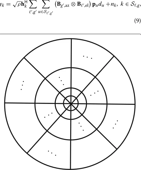
The impact of DFT prebeamformers can be regarded as cell splitting. The cell is cut into subsectors in the azimuth direction and annular regions in the elevation directions,
as depicted in Fig. 2. We denote by G the number of
subsectors;Lthe number of annular regions. These sub-sectors and annular regions form groups, and the user set in the,g-th group is denoted byS,g. The received signal of thekth user is
yk=√ρhHk ,g
u∈S,g
Bg,az⊗B,el
pudu+nk, k∈S,g,
(9)
Fig. 2Cell splitting by DFT prebeamforming in the azimuth and
elevation directions, respectively
where Bg,az andB,el are the DFT prebeamforming for
the gth subsector and the th annular region, respec-tively. Assume that the cell is split uniformly and DFT prebeamformers have an equal number of columns of DFT matrix, i.e., Bg,az = Faz
:,g −1baz+(1 :baz)
, where the (m,p)-th entry of the DFT matrixFaz∈CM×M
is [Faz]m,p= e
−j2π(m−1)(p−1)/M
√
M , andbaz =
M G
. Similarly, B,el = Fel[ :,
−1bel+(1 :bel)], where the (m,p)-th
entry of the DFT matrix Fel ∈ CN×N is [Fel]m,p= e−j2π(m√−1)(p−1)/N
N , andbel =
N L
. The 3D prebeamformer
for thekth user isB,g = Bg,az⊗B,el ∈ CMN×bazbel and
the effective channel isBH,ghk∈Cb, whereb=bazbel. The
DFT prebeamforming provides the lower dimensional effective channels, compared to the large-dimensional instantaneous CSI. Based on these effective channels, the complexity of the multi-user precoding becomes lower. A block diagram of the 3D beamforming scheme is shown in Fig. 3.
3.2 Low-complexity user grouping algorithm
DFT prebeamformers are used for cell splitting and form groups and then users are partitioned into these groups based on the statistical CSI. We develop a low-complexity 2D fixed quantization user grouping (2D-FQUG) algo-rithm in Algoalgo-rithm 1. Due to the separability of the 3D channel, We first find the annular region index for the user and then the subsector index.
Algorithm 12D-FQUG algorithm
Input:
Azimuth and elevation correlations, Rk,az and
Rk,el,∀k; Output:
User set of the,g-th group,S,g,∀,g; Fork=1,. . .,K,
1: Perform EVDs of Rk,az and Rk,el, respectively, and
obtainUk,azandUk,el;
2: Find the annular region indexaccording to
=arg min
Uk,elU H
k,el−B,elBH,el 2
, ∀, (10)
where · denotes the Frobenius norm;
3: Find the subsector indexgaccording to
g=arg min
g
Uk,azUHk,az−Bg,azBHg,az 2
,∀g, (11)
4: Add userkto setS,g; 5: return S,g,∀,g.
Fig. 3A block diagram of 3D beamforming. The second-stage beamforming is the Kronecker product of DFT prebeamforming in the azimuth and elevation directions and the first-stage precoding is designed based on effective channels with lower dimension
uniformly distributed due to some strong scatters. Hence, the eigenvalues of the correlation of each user change [34], so does the eigenvector matrix corresponding to the ordered eigenvalues; our proposed algorithm still works but is achieving a different user grouping result.
The 2D-FQUG is a separable user grouping algorithm with lower complexity, comparing to the overall algorithm which is based on the criterion,
(,g)=arg min (,g)
UkUHk −B,gBH,g
2
,∀,g. (12)
The complexities of these two algorithms are analyzed in terms of floating-point operation (FLOP) and we count each complex operation as one FLOP [35]. The complex-ity mainly comes from matrix products and EVDs. In (10), Uk,elUHk,el needs(2rk,el−1)N2FLOPs,B,elBH,el requires
(2bel−1)N2FLOPs,Uk,elUHk,el−B,elBH,elcostsN2FLOPs,
andUk,elUHk,el−B,elBH,el 2
needs 2N2−1 FLOPs,
yield-ing a total number of (2rk,el +2bel+1)N2−1 FLOPs.
Similarly, (11) requires(2rk,az+2baz+1)M2−1 FLOPs. In
the overall algorithm, (12) needs(2rk,azrk,el+2bazbel+1)
(MN)2 − 1 FLOPs. For matrix EVD computation of
each user, we consider a maximum number ofN3+M3
andM3N3 FLOPS in 2D-FQUG and overall algorithms,
respectively [36].
Thus, the total complexity of 2D-FQUG algorithm is
Cf=
2belN2+N2+2bazM2+M2−2+N3+M3
K+
k
2rk,elN2+2rk,azM2
≈
2
L +1
N3+N2+
2
G+1
M3+M2−2
K
+
k
2rk,elN2+2rk,azM2FLOPs,
(13)
which is O(N3+M3). And the total complexity of the overall algorithm is
Co =
2bazbelM2N2+M2N2−1+M3N3
K+2M2N2
k
rk,azrk,el
≈
2
GL+1
M3N3+M2N2−1
K
+ 2M2N2
k
rk,azrk,el FLOPs, (14)
3.3 Multi-user precoding
The first-stage precoding can be designed per group indi-vidually, after user partition. However, group inter-ferences exist, because the eigenvector matrix of channel correlation is not exactly equal to the Kronecker prod-uct of the azimuth and elevation DFT prebeamform-ers. This is because in practice, the angular supports of users may be overlapping and users cannot be sepa-rated strictly. Moreover, the inter-group interferences are severe between the adjacent groups, and hence the multi-user precoders need to consider not only the intra-group interferences but also the adjacent-group interferences.
Conventional ZF precoding can achieve this goal, but it requires that the number of transmit antennas must be equal to or larger than that of receive antennas combined. Nevertheless, due to cell splitting, the effective number of BS antennas serving each group is equal tobwhich is smaller thanMN. When users are located in one area, the requirement of ZF precoding may not be satisfied. Thus, we adopt SLNR precoding as the multi-user precoders, which has no restriction on the number of antennas [21]. For mitigating both the intra-group and adjacent-group interferences, the SLNR precoding for thekth user is
pk=
where λk is a regularization parameter to guarantee
pk =1,H˜k =[H(,g−1),H(,g+1),H(−1,g),H(+1,g),Hk]∈ CMN×(Uk−1), where [H(,g−1),H(,g+1),H(−1,g),H(+1,g)]
is an extended channel matrix formed by user channels in the adjacent groups of the kth user, Hk ∈ CVk−1
This SLNR precoding surely is not as good as that considering all-group interferences, but it has lower com-plexity. For comparison, we consider the SLNR precoding for suppressing all-group and intra-group interferences, respectively, which are
whereH˙kis an extended channel matrix that excludeshk only.
The source of the complexity difference is
BH,gH˜kH˜HkB,g,BH,gH˙kH˙HkB,g, and BH,gHkHHkB,g. The general complexity of these terms can be written as
Ct=(2bMN−b+2b2)x−b2FLOPs, (18)
where x = Uk − 1,K − 1, and Vk − 1 for (15),
(16), and (17), respectively. We denote this term by , so the general SLNR precoding is expressed as pk,g =
λk,g ρ1Ib+ −1
BH,ghk. Assuming that 1ρIb is known
a prior, ρ1Ib + needs b real summations, which is
equivalently transferred to b2 FLOPs here. ρ1Ib+ −1
requires b3 + b2 + b FLOPs. BH,ghk costs 2bMN −
b FLOPs wherein Hermitian transposition requires no
FLOP. ρ1Ib+
which requires 2b + 1 FLOPs. A simple
multi-plication λk,g ρ1Ib+
Thus, for our proposal and SLNR precoding consider-ing all-group and intra-group interferences, the respective total complexities for all users are
Cp=
We unify (20)–(22) into a general form as
where z = kUk,K2,kVk for (20), (21), and (22), respectively. The first derivative ofCgwith respect tobis
∂Cg
increasing function with respect tob. When the number of groups increases, the dimension of effective channelb
decreases and the complexity is reduced. The first deriva-tive ofCgwith respect toMis
tonically increasing function with respect toM. Similarly,
Cg is a monotonically increasing function with respect
toN. Thus, when the number of BS antennas increases, the complexity becomes high. And larger number of users brings higher complexity. Evidently, there is a trade-off between performance and complexity, and in the simu-lation section, we will show that our proposal is a good balance.
4 Performance analysis
In this section, we analyze the performance of our pro-posal. The performance metric is sum rate, which is
r=
K
k=1
log2(1+SINRk), (26)
where the SINR for thekth user is
SINRk=
The numerator is the signal power, the first term in the denominator is the interference power, and the second term in the denominator is the noise power which is equal to 1. We compute the SINR via the deterministic equiva-lent method [3, 23–26] and then obtain the sum rate by (26). The derived SINR is a deterministic quantity in the almost sure (a.s.) asymptotics. Since we apply the DFT prebeamformer to reduce the system dimension and the SLNR precoding is dependent on the effective channel, the studied system dimension in deterministic equivalent approximation isbinstead ofMN, and the a.s. asymptotics can be written as
SINR−SINR◦−−−−−−−→a.s.
b,Ku→+∞
0, (28)
where Ku is the number of users in the studied system,
SINR is regarded as a sequence with increasing system
dimensionbandKu, andSINR◦is its deterministic equiv-alent.b,Ku → +∞denotesbandKugo to infinity at the
For brevity of expression, we rewrite (28) asSINRSINR◦.
SINR◦ is obtained by random matrix theory [23]. Refer-ring to [37], when the number of antennas increases, the variance of channel capacity is reduced such that the instantaneous mutual information is deterministic approximately and only depends on the statistical CSI. So, we can analyze the performance based on deterministic equivalents without the need of heavy Monte Carlo sim-ulations. Using deterministic equivalents, we derive the approximate SINR in the following theorem.
Theorem 1In a 3D massive MIMO system depicted
in (9) where the SLNR precoding is given in (15), the approximate SINR of the kth user, in the sense of (28), is
whereTuandδscan be obtained similarly as(31)and(32),
respectively, andδλ
k =[δλk,1,. . .,δλk,|Tk|]
Proof The signal power for thekth user is
ρ|hHkB,gpk|2=ρ|ˇhHkpk|2
The SLNR precoding for thekth user is related to other user channels. In order to use deterministic equivalents to calculate the interference power, we divide the interfer-ing user channels into two groups: one is containinterfer-ing user channels which are not included by the precoding vec-tor of thekth user, i.e., the users are not located in either the adjacent groups of the(,g)-th group or in the(,g) -th group itself, while -the o-ther is -the opposite case. We denote these two groups byIn,kandIy,k, respectively. So, the interference power for thekth user is the sum of these two parts, which is
ρ the interference power is
ρ|ˇgHk,,gpu|2=ρλugˇHk,,gC−u1hˇuhˇHuC−u1gˇk,,g
ρ|ˇgHk,,gpu|2=ρλugˇHk,,gC− obtained using Lemma 1 in [3] where
Du,k= Referring to Lemma 4 and Theorem 2 in [3], we approx-imate the regularization parameter in (19) by
λk =
Inserting (48), (52), (56) and (58) into (27), we obtain (30), which concludes the proof.
5 Numerical results
In this section, we evaluate the performance of the pro-posed scheme by numerical simulations. The perfor-mance metric is sum rate in (26). We assume that the BS is elevated and seldom obstructed by local scatters, while users are located on the street level and surrounded by
scatters. The BS employs anN×MURA withM
anten-nas in each row andNrows in the elevation direction. The default configuration parameters of this section are the following: the BS antenna spacing divided by the carrier wavelength in (4) isD=0.5; the AoA and the associated AS in the azimuth direction are randomly distributed in [−180◦, 180◦] and [ 0, 20◦], respectively; in the elevation direction, the AoA and AS intervals are [−90◦, 90◦] and [ 0◦, 10◦], respectively; the cell radius is 1600 m and the cell-hole radius is 100 m, i.e., the distance between thekth user and the BS is in the range of [ 100, 1600] m when con-sidering the path lossβk = r1γ
k
in (2), and the path loss exponent isγ =3.8.
First, we show the tightness of the SINR approximations with simulation results in Fig. 4. The number of elevation
BS antennas is N = 10 and the number of azimuth BS
antennas takes values in [ 10, 30, 50, 70, 90]. The number of users isK = 10. The cell is split intoG = 4 subsec-tors andL=4 annular regions. The rank of azimuth DFT prebeamformer isbaz =
M G
=[ 2, 7, 12, 17, 22] and the rank of elevation DFT prebeamformer isbel=
N L
=2.
The dimension of effective channel is b = bazbel =
[ 4, 14, 24, 34, 44]. We can see that with the increasing number of BS antennas, the approximations are approach-ing to the numerical ones. It is validated that the deter-ministic equivalent approximations are tight whenband
K are not infinitely large, which is suitable for practical scenarios. So, we will use the approximate SINRs for per-formance evaluation instead of the lengthy Monte Carlo simulations in the following parts.
Then, we compare two user grouping algorithms in Fig. 5. One is the 2D-FQUG algorithm and the other is overall grouping method based on (12). The number of
users is K = 10. We evaluate two groups of
perfor-mance. One is that the number of azimuth BS antennas
is varying as M =[ 80, 100, 120] when the number of
elevation BS antennas is fixed as N = 10. The other
is that N =[ 10, 20, 30] with M = 80. Both groups of
parameters are large enough to guarantee the tightness of asymptotic SINR. The cell is split intoG = 4 subsectors
andL = 4 annular regions. Obviously, these two
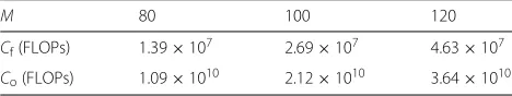
algo-rithms are equivalent. Tables 1, 2, 3, 4, and 5 show that the complexities of 2D-FQUG and overall algorithms with varyingM,N,G,L, andK, respectively, based on (13) and (14). We find that the proposed 2D-FQUG algorithm has lower complexity than the overall one under all circum-stances. Based on the analysis in Section 3.2, the com-plexities of algorithms mainly come from the operations
Fig. 4Sum rate (bps/Hz) versus number of BS antennas for the
Fig. 5Sum rate (bps/Hz) versus transmit power (dBw) using 2D-FQUG and overall algorithms
of matrix product and EVD, involving channel correla-tions, eigenvector matrices of channel correlacorrela-tions, and the DFT prebeamforming. According to Tables 1 and 2, with the increasing number of BS antennas and other fixed parameters, the complexities of both algorithms become higher, since the dimensions of matrices become larger. In Tables 3 and 4, the complexities are reduced as the number of groups is increasing, but the tendency is not very evident. This is because only the dimension of the DFT prebeamforming is reduced and other matri-ces are not affected since the number of BS antennas is fixed. In Table 5, we change the number of users while keeping other parameters constant, which causes an evi-dent increase in complexities of both algorithms, due to the increasing number of summation of the complexity of each user.
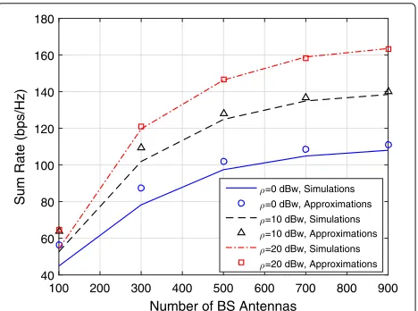
The performance of our proposed multi-user precoding scheme is illustrated in Fig. 6, and the associated com-plexities are summarized in Table 6. The transmit power
is ρ = 20 dBw. The number of users isK = 20. The
number of azimuth BS antennas isM=64 and the
num-ber of elevation BS antennas isN = 12. The number of
subsectors isG =[ 4, 8, 16, 32, 64], the number of annu-lar regions is L = 4, and the total number of groups is
Table 1Complexities of 2D-FQUG and overall algorithms with
N=10,G=L=4, andK=10
M 80 100 120
Cf(FLOPs) 1.39×10⁷ 2.69×10⁷ 4.63×10⁷
Co(FLOPs) 1.09×10¹⁰ 2.12×10¹⁰ 3.64×10¹⁰
GL =[ 16, 32, 64, 128, 256]. For comparison, we evaluate three additional schemes, which are the SLNR precoding for suppressing all-group and intra-group interferences denoted by “all groups” and “one group” in the figure, respectively, and the generalized maximum ratio trans-mission (MRT) as a benchmark [38]. The generalized MRT for thekth user ispk,mrt=uk,az⊗uk,el, whereuk,az
anduk,el are the eigenvectors associated with the largest
eigenvalues ofRk,azandRk,el, respectively. So,uk,az⊗uk,el
is the eigenvector corresponding to the largest eigenvalue ofRk. Without user grouping, the received signal of the
kth user in (9) is rewritten asyk = √ρhHk
upu,mrtdu+nk. The complexities of our proposal and the schemes for suppressing all-group and intra-group interferences in Table 6 are the sum of the complexities of 2D-FQUG user grouping algorithm and the SLNR precoding, which are given byCfandCg, in (13) and (23) respectively. The
com-plexity of the generalized MRT originates only from the precoding approach. For each user, the generalized MRT involves EVD ofRk,azandRk,el and the Kronecker
prod-uct of uk,az anduk,el, which require M3 +N3 and MN
FLOPs, respectively. Thus, its total complexity of all users is(M3+N3+MN)KFLOPs. In Table 6, the generalized MRT has the lowest complexity among all schemes.
Table 2Complexities of 2D-FQUG and overall algorithms with
M=80,G=L=4, andK =10
N 10 20 30
Cf(FLOPs) 1.39×10⁷ 1.41×10⁷ 1.46×10⁷
Table 3Complexities of 2D-FQUG and overall algorithms with
M=80,N=10,L=4, andK=10
G 4 8 16
Cf(FLOPs) 1.39×10⁷ 1.26×10⁷ 1.20×10⁷
Co(FLOPs) 1.11×10¹⁰ 1.08×10¹⁰ 1.06×10¹⁰
Considering the three schemes which are our proposal and the ones for suppressing all-group and intra-group interferences, the dimension of the effective channel vec-tor isb=bazbel=
M G NL
. So, the determination ofbis equivalent to that of the number of groupsGL, when the number of BS antennas is fixed. In Sections 3.2 and 3.3, we have concluded theoretically that with largerGLand smallerb, the complexities of both 2D-FQUG user group-ing algorithm and SLNR precodgroup-ing are reduced. From Table 6, the complexities of our proposal and the schemes for suppressing all-group and intra-group interferences are decreasing with larger number of groups. Besides, the choice ofbandGLalso affects the sum-rate performance, as shown in Fig. 6. In Fig. 6, with the increasing num-ber of groups, the performance is decreasing. The scheme considering all-group interferences has gradually worsen-ing performance. This is because when the number of groups increases, the ranks of both the DFT prebeam-forming and the effective channels become smaller. Some significant eigenmodes are not taken into account by the SLNR precoding, which leads to larger interference and worse sum-rate performance. For our proposal, another reason for degrading the performance is that when the cell is partitioned into more groups, the group inter-ferences come from not only adjacent groups but also distant groups, so the inter-group interferences become severe and the proposed algorithm does not work effi-ciently and achieves almost the same performance as the SLNR precoding for suppressing the intra-group interfer-ences. And with the increasing number of groups, users are more likely to be partitioned into individual groups, so the performance of the SLNR precoding for suppress-ing the intra-group interferences becomes worse. When
the number of subsectors isG = 64 and the number of
groups isGL=256, the rank of the DFT prebeamforming for each subsector is baz =
M G
= 1, which
approxi-mates the generalized MRT. So, the performances of the SLNR precoding for suppressing the intra-group interfer-ences and our proposal approach to that of the generalized
MRT whenGL=256.
Table 4Complexities of 2D-FQUG and overall algorithms with
M=10,N=80,G=4, andK=10
L 4 8 16
Cf(FLOPs) 1.38×10⁷ 1.25×10⁷ 1.18×10⁷
Co(FLOPs) 1.06×10¹⁰ 1.02×10¹⁰ 1.01×10¹⁰
Table 5Complexities of 2D-FQUG and overall algorithms with
M=80,N=10, andG=L=4
K 10 20 30
Cf(FLOPs) 1.39×10⁷ 2.77×10⁷ 4.14×10⁷
Co(FLOPs) 1.11×10¹⁰ 2.15×10¹⁰ 3.18×10¹⁰
There is a trade-off between the sum-rate performance and complexity. The SLNR precoding for suppressing the all-group interferences is the best among these four schemes. But it has the highest complexity. The gener-alized MRT has the lowest complexity but the poorest performance. Our proposal works better than the one considering the intra-group interferences and the gener-alized MRT, with moderate complexity. So, the proposed scheme is a good balance between performance and com-plexity.
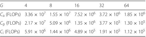
Tables 7, 8, 9, 10, and 11 show the complexity compar-ison of three SLNR precoding approaches with varying different parameters. The complexity of the proposal lies between the SLNR precoding considering all-group and intra-group interferences. The complexities are reduced with larger number of groups and become higher with more BS antennas and users.
6 Conclusions
In this paper, we proposed a low-complexity 3D beam-forming scheme for the massive MIMO system. We used
two-stage beamforming where the second-stage
pre-beamforming is a Kronecker product of azimuth and elevation DFT prebeamformers. These DFT prebeam-formers are used for cell splitting. We developed a low-complexity 2D-FQUG user grouping algorithm using only statistical CSI to partition users into groups. The first-stage beamforming is SLNR precoding based on
Fig. 6Sum rate (bps/Hz) versus number of groups with different
Table 6Complexities (FLOPs) of four schemes in Fig. 6 with
M=64,N=12,L=4, andK =20
G 4 8 16 32 64
All groups 4.81×1072.87×1072.01×1071.59×1071.39×107
Proposal 3.62×1071.83×1071.39×1071.26×1071.22×107
One group 2.04×1071.46×1071.30×1071.24×1071.22×107
Generalized MRT 5.29×1065.29×1065.29×1065.29×1065.29×106
Table 7Complexities of three SLNR precoding approaches with
M=64,N=12,L=4, andK =20
G 4 8 16 32 64
Ca(FLOPs) 3.36×10⁷ 1.55×10⁷ 7.52×10⁶ 3.72×10⁶ 1.85×10⁶
Cp(FLOPs) 2.17×10⁷ 5.09×10⁶ 1.35×10⁶ 3.77×10⁵ 1.30×10⁵
Ci(FLOPs) 5.91×10⁶ 1.44×10⁶ 4.89×10⁵ 1.91×10⁵ 1.12×10⁵
Table 8 Complexities of three SLNR precoding approaches with
M=12,N=64,G=4, andK=20
L 4 8 16 32 64
Ca(FLOPs) 3.36×10⁷ 1.55×10⁷ 7.52×10⁶ 3.72×10⁶ 1.85×10⁶
Cp(FLOPs) 2.16×10⁷ 5.90×10⁶ 1.46×10⁶ 4.50×10⁵ 1.21×10⁵
Ci(FLOPs) 6.76×10⁶ 2.03×10⁶ 5.22×10⁵ 2.09×10⁵ 9.32×10⁴
Table 9Complexities of three SLNR precoding approaches with
N=64,L=G=4, andK=20
M 8 12 16 20 24
Ca(FLOPs) 1.46×10⁷ 3.35×10⁷ 6.09×10⁷ 9.73×10⁷ 1.43×10⁸
Cp(FLOPs) 9.08×10⁶ 2.16×10⁷ 3.98×10⁷ 6.42×10⁷ 9.73×10⁷
Ci(FLOPs) 2.26×10⁶ 6.13×10⁶ 1.22×10⁷ 2.11×10⁷ 3.34×10⁷
Table 10Complexities of three SLNR precoding approaches
withM=64,L=G=4, andK=20
N 8 12 16 20 24
Ca(FLOPs) 1.46×10⁷ 3.35×10⁷ 6.09×10⁷ 9.73×10⁷ 1.43×10⁸
Cp(FLOPs) 9.42×10⁶ 2.10×10⁷ 4.03×10⁷ 6.42×10⁷ 9.35×10⁷
Ci(FLOPs) 2.12×10⁶ 5.50×10⁶ 1.05×10⁷ 1.89×10⁷ 2.96×10⁷
Table 11 Complexities of three SLNR precoding approaches
withM=64,N=12, andL=G=4
K 10 20 30 40 50
Ca(FLOPs)ˆ 8.94×10⁶ 3.35×10⁷ 7.38×10⁷ 1.30×10⁸ 2.01×10⁸
Cp(FLOPs) 5.80×10⁶ 2.34×10⁷ 4.56×10⁷ 8.22×10⁷ 1.33×10⁸
Ci(FLOPs) 2.36×10⁶ 7.54×10⁶ 1.04×10⁷ 1.63×10⁷ 2.53×10⁷
the effective channels formed by DFT prebeamformers and instantaneous CSI. The designed SLNR precoding considers intra-group and adjacent-group interferences. We derived the approximate SINR for our proposal. We analyzed that the complexities of both 2D-FQUG user grouping algorithm and SLNR precoding are reduced with larger number of groups and become higher with more BS antennas and users. Numerical results show that the 2D-FQUG algorithm achieves the same sum-rate per-formance as the overall grouping method but has lower complexity. Our proposal works better than the one con-sidering the intra-group interferences and the generalized MRT, and its complexity lies between the SLNR precod-ing for suppressprecod-ing all-group interferences and the one considering the intra-group interferences. So, the pro-posed scheme is a good balance between performance and complexity.
Acknowledgments
This work was supported in part by the National Natural Science Foundation of China under Grants 61372101, National High Technology Project of China 2015AA01A703, the 863 Program of China under Grant 2014AA01A704th, the National Natural Science Foundation of China under Grants 61422105 and 61531011, the Natural Science Foundation of Jiangsu Province under Grant BK20130019, the Research Project of Jiangsu Province under Grant BE2015156.
Competing interests
The authors declare that they have no competing interests.
Received: 30 December 2015 Accepted: 6 September 2016
References
1. TL Marzetta, Noncooperative cellular wireless with unlimited numbers of base station antennas. IEEE Trans. Wirel. Commun.9(11), 3590–3600 (2010)
2. F Rusek, Persson D, Buon KL, Larsson EG, Marzetta TL, Edfors O, Tufvesson F, Scaling up MIMO: Opportunities and challenges with very large arrays. IEEE Signal Proc. Mag.30(1), 40–60 (2013)
3. J Hoydis, S ten Brink, M Debbah, Massive MIMO in the UL/DL of cellular networks: how many antennas do we need? IEEE J. Sel. Areas Commun.
31(2), 160–171 (2013)
4. E Larsson, O Edfors, F Tufvesson, T Marzetta, Massive MIMO for next generation wireless systems. IEEE Commun. Mag.52(2), 186–195 (2014) 5. T Marzetta, L Caire, D Giuseppe, C-L Merouane, I Mohammed, K Saif,
Special issue on massive MIMO. J. Commun. Netw.15(4), 333–337 (2013) 6. JG Andrews, S Buzzi, C Wan, SV Hanly, A Lozano, ACK Soong, JC Zhang,
What will 5G be? IEEE J. Sel. Areas Commun.32(6), 1065–1082 (2014) 7. L You, X Gao, AL Swindlehurst, W Zhong, Channel acquisition for massive
MIMO-OFDM with adjustable phase shift pilots. IEEE Trans. Signal Process.
64(6), 1461–1476 (2016)
8. Y-H Nam, LN Boon, K Sayana, Y Li, J Zhang, Y Kim, J Lee, Full-dimension MIMO (FD-MIMO) for next generation cellular technology. IEEE Commun. Mag.51(6), 172–179 (2013)
9. F Yuan, Tucker decomposition for rotated codebook in 3D MIMO system under spatially correlated channel. IEEE Trans. Veh. Technol.PP(99), 1–1 (2015)
10. TA Thomas, FW Vook, E Mellios, GS Hilton, AR Nix, E Visotsky, inProc. IEEE Vehicular Technology Conference (VTC Spring). 3D extension of the 3GPP/ITU channel model, (Dresden, 2013), pp. 1–5
12. Q-U-A Nadeem, A Kammoun, M Debbah, M-S Alouini, A generalized spatial correlation model for 3D MIMO channels based on the Fourier coefficients of power spectrums. IEEE Trans. Signal Process.63(14), 3671–3686 (2015)
13. K Zheng, L Zhao, J Mei, B Shao, W Xiang, L Hanzo, Survey of large-scale MIMO systems. IEEE Commun. Surv. Tutorials.17(3), 1738–1760 (2015) 14. TA Thomas, FW Vook, inProc. IEEE Global Communications Conference
(GLOBECOM). Transparent user-specific 3D MIMO in FDD using beamspace methods, (Vancouver, BC, 2014), pp. 1–6
15. L Xie, L Li, X Li, inProc. IEEE Vehicular Technology Conference (VTC Fall). Sum rate analysis of multicell MU-MIMO with 3D user distribution and base station tilting, (Vancouver, BC, 2014), pp. 1–6
16. F Tan, H Gao, T Lv, J Zeng, inProc. IEEE Globecom Workshops (GC Wkshps). Achievable sum rate analysis of ZF receivers in 3D MIMO with Rayleigh/log-normal fading channels, (Austin, TX, 2014), pp. 815–820 17. A Adhikary, J Nam, J-Y Ahn, G Caire, Joint spatial division and
multiplexing—the large-scale array regime. IEEE Trans. Inf. Theory.59(10), 6441–6463 (2013)
18. D Ying, FW Vook, TA Thomas, DJ Love, A Ghosh, inProc. IEEE Int. Conf. Commun. (ICC). Kronecker product correlation model and limited feedback codebook design in a 3D channel model, (Sydney, 2014), pp. 5865–5870
19. U Grenander, G Szegõ,Toeplitz Forms and Their Applications. (University of California Press, Berkeley and Los Angeles, 1958)
20. R Gray,Toeplitz and Circulant Matrices: A Review. (Now Publishers Inc, The Netherlands, 2006)
21. M Sadek, A Tarighat, AH Sayed, A leakage-based precoding scheme for downlink multi-user MIMO channels. IEEE Trans. Wirel. Commun.6(5), 1711–1721 (2007)
22. M Schubert, H Boche, Solution of the multiuser downlink beamforming problem with individual SINR constraints. IEEE Trans. Veh. Technol.53(1), 18–28 (2004)
23. R Couillet, M Debbah,Random Matrix Methods for Wireless Communications. (Cambridge University Press, École Supérieure d’Électricité, Gif sur Yvette, France, 2011)
24. W Hachem, O Khorunzhiy, P Loubaton, J Najim, L Pastur, A new approach for capacity analysis of large dimensional multi-antenna channels. IEEE Trans. Inf. Theory.54(9), 3987–4004 (2008)
25. VK Nguyen, JS Evans, inProc. of IEEE Global Commun. Conf. (GLOBECOM). Multiuser transmit beamforming via regularized channel inversion: a large system analysis, (New Orleans, LO, 2008), pp. 1–4
26. R Muharar, J Evans, inProc. of IEEE Int. Conf. Commun. (ICC). Downlink beamforming with transmitside channel correlation: a large system analysis, (Kyoto, 2011), pp. 1–5
27. AO Martinez, E de Carvalho, JO Nielsen, inProc. IEEE Globecom Workshops (GC Wkshps). Towards very large aperture massive MIMO: a measurement based study, (Austin, TX, 2014), pp. 281–286
28. H Ji, Y Kim, J Lee, E Onggosanusi, Y Nam, J Zhang, B Lee, B Shim,Overview of full-dimension MIMO in LTE-advanced pro. https://arxiv.org/abs/1601. 00019
29. KT Truong, RW Heath, Impact of spatial correlation and distributed antennas for massive MIMO systems (2013). http://users.ece.utexas.edu/~rheath/ presentations/2013/Asilomar_massive_MIMO_spatial_correlation_ and_DAS_ver2.2.pdf. Accessed 2013
30. W Fan, P Kyosti, S Fan, JO Nielsen, X Carreno, GF Pedersen, MB Knudsen, in
Proc. IEEE Vehicular Technology Conference (VTC Fall). 3D channel model emulation in a MIMO OTA setup, (Las Vegas, NV, 2013), pp. 1–5 31. A Kammoun, H Khanfir, Z Altman, M Debbah, M Kamoun, Preliminary
results on 3D channel modeling: from theory to standardization. IEEE J. Sel. Areas Commun.32(6), 1219–1229 (2014)
32. A Kammoun, A MüAller, E Björnson, M Debbah, Linear precoding based on polynomial expansion: large-scale multi-cell MIMO systems. IEEE J. Sel. Topics Signal Process.8(5), 861–875 (2014)
33. D-s Shiu, GJ Foschini, MJ Gans, JM Kahn, Fading correlation and its effect on the capacity of multielement antenna systems. IEEE Trans. Commun.
48(3), 502–513 (2000)
34. L You, X Gao, X-G Xia, N Ma, Y Peng, Pilot reuse for massive MIMO transmission over spatially correlated Rayleigh fading channel. IEEE Trans. Wirel. Commun.14(6), 3352–3366 (2015)
35. R Hunger, Floating point operations in matrix-vector calculus (2007). https://mediatum.ub.tum.de/doc/625604/625604.pdf. Accessed 2007
36. H Jamali-Rad, T van Waterschoot, G Leus, inProc. 2011 WIC/IEEE SP Symp. Inf. Theory Signal Process. Benelux (WICSP ’11). Anchorless cooperative localization for mobile wireless sensor networks, (Brussels, Belgium, 2011), pp. 9–16
37. BM Hochwald, TL Marzetta, V Tarokh, Multiple-antenna channel hardening and its implications for rate feedback and scheduling. IEEE Trans. Inf. Theory.50(9), 1893–1909 (2004)
38. E Björnson, R Zakhour, D Gesbert, B Ottersten, Cooperative multicell precoding: rate region characterization and distributed strategies with instantaneous and statistical CSI. IEEE Trans. Signal Process.58(8), 4298–4310 (2010)
Submit your manuscript to a
journal and benefi t from:
7Convenient online submission
7 Rigorous peer review
7Immediate publication on acceptance
7 Open access: articles freely available online
7High visibility within the fi eld
7 Retaining the copyright to your article