IJEDR1402252
International Journal of Engineering Development and Research (www.ijedr.org)2869
To Study Lifting Operation Plan of Toppling Process
from Preliminary Hazard Analysis to Prevent Hazard
1
H. R. Patel,
2Pravin Patel
1Research Scholar, 2Associate professor, 1
M.Tech (Industrial Safety Engineering)
1, 2 Dept. of Fire technology and Safety Engineering, IES-IPS Academy, Indore (M.P), India
________________________________________________________________________________________________________ Abstract - Lifting operations and associated equipment have become commonplace within the all over world of various industries. On the other hand, recent high shape accidents involving lifting equipment have shown that the effect of its mishandling can have serious cost and health implications. The main aim of this research was to study lifting plan with the help of lifting operation process (LOP) via preliminary hazard analysis (PHA). People perform PHA and LOP studies and, therefore, such studies themselves are subject to various possible human failures. Much less attention has been paid to the human factors that influence the performance of PHA and LOP studies than human factors that influence hazard scenarios. Human failures in the performance of PHA and LOPA studies should be of significant concern to practitioners as such studies are difficult and time-consuming activities that place significant demands on participants, which increases the chance that errors will be made. Human factors such as eagerness to rely on the unsubstantiated opinions of others, groupthink, underestimation of the frequencies of low-probability, high-consequence events, and allowing a false sense of accomplishment to distract from implementing study results must be recognized and addressed. This paper identifies a proper preliminary steps that can influence the quality of PHA of tools and tackles for lifting equipments with toppling process and LOP studies covering preparing for, conducting, recording, documenting, and following-up on studies. Lifting operation plan; its design and analysis has been done with PHA process and its result shows that it may resolve the study of quality related to lifting plan. The findings revealed six main points to improve safety in lifting operations. These are: through planning; training; equipment selection, use and inspection; feedback/communication; appointed person’s role; and database. Thorough planning of lifting operations has positive effects on safety.
Index Terms - Preliminary hazard analysis, Toppling process, Lifting operation plan
________________________________________________________________________________________________________
I.INTRODUCTION
Today, in this exciting daily life, world comprises of systems and risks. With systems and technology there also comes the exposure to mishaps because systems can fail or work improperly which results in damage, injury and deaths. The possibility that a system fails and results in death, injury, damage and the like are referred to as mishap risk. The key to system safety and effective risk management is the identification and mitigation of hazards. To successfully control hazards, it is necessary to understand hazards and know how to identify them. With this requirement Hazard Analysis comes into role.
The result of a hazard analysis is the identification of different type of hazards. It may in single existence or in combination with other hazards (sometimes called events) and conditions become an actual Functional Failure or Accident (Mishap). The way this exactly happens in one particular sequence is called a scenario. In this project developed this guidance primarily for any Fabrication and Manufacturing Compnies’s lifting operations, but the principles described are relevant to all lifting operations and generically to lifting operations anywhere. On a typical vessel and any Components, lifting is endemic to operations and ranges from lifting of stores and spares handling through to complicated and heavy lifts. One survey showed that there could be more than 200 different lifting operations on a vessel. Each lifting operation has a risk of injury to people. It is worth noting that many accidents occur in what are perceived as low risk everyday operations. It is therefore important to ensure that appropriate procedures are in place to try to ensure that lifting teams remain alert to all likely risks regardless of the ease or difficulty of an operation. The guidance offers basic criteria. It is based on existing practice collated from major companies, adopts improved methods for lifting and is intended to be of use for world-wide operations. This guidance is intended to show essential components that should be included in company procedures for lifting operations and offers advice on the steps within a lifting operation process that will promote safety. Member companies use their procedures in operations internationally, supplemented, if necessary, by any additional local regulatory demands. The main objective is that, regardless of location, if each step of the process outlined in this guidance is followed and suitably applied then every lift should be carried out in a safe manner because it is:
- Completed within an appropriate management system; - Properly Planned
- Prepare Lifting Plan with calculations
- Prepare Planning a Path Way of Component which one is lifted. - Supervised; and
IJEDR1402252
International Journal of Engineering Development and Research (www.ijedr.org)2870
II.LITERATURE SURVEYThe selection of equipment can have effects on the effectiveness and efficiency of the site, depending on how well the equipment is suited to its environment. The literature review would suggest that there are two depths of equipment planning, rigorous and intuitive. The selection of cranes often has a relationship with the types of potential accidents that may occur [1]. The factors affecting the selection of cranes are: site specific requirements; culture; cost; and availability [2]. The accident rates can be reduced through usage of safety devices and by legislation. The safety devices introduced to cranes and other lifting equipment can be put into one of five major categories: Anti Current devices; Anti Upset devices; Operator and Rigger Protection mechanisms; Anti Collision devices and other safety devices which include hooks with safety latches [3]. Process Hazard Analysis (PHA) [4] and Layers of Protection Analysis (LOPA) [5] address failures in processes that can result in hazard scenarios with adverse impacts on such receptors as people, property and the environment. PHA is used to identify hazard scenarios and LOPA is used to evaluate their risk. Often, human failures are causes of, or contributors to, hazard scenarios, and various human factors influence the rates of failure [6], [7]. Process safety regulations require that such human failures and human factors be addressed in PHA [8] and by implication in LOPA. Other failure types such as equipment failures and external events must also be addressed [9]. The role of human factors in the workplace for the process industries is well known [9]. The role of human error in accidents continues to be addressed [10]. People perform PHA and LOPA studies and, therefore, such studies are subject to various possible human failures influenced by various human factors. However, much less attention has been paid to the human factors that influence the performance of PHA and LOPA studies than human factors that influence process risks. One study looked at some of the psychological processes involved in hazard and operability (HAZOP) studies, specifically, interactions between team members and how team members perceive, remember, judge and reason [11]. Human failures in the performance of PHA and LOPA studies should be of significant concern to practitioners as they can have a significant adverse impact on study results. PHA studies involve considerable subjective judgment by team members. Indeed, LOPA was developed to provide a more rational and objective approach to making decisions on the tolerability of risk from hazard scenario.
III.PROBLEM
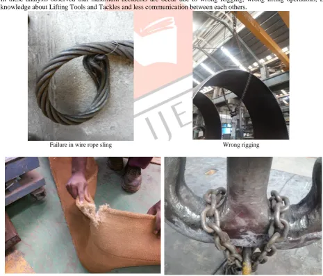
Problems Observed through P.H.A (Preliminary Hazard Analysis) in various companies.
In these analysis observed that maximum accidents are occur due to wrong Rigging, wrong lifting operations, Lack of knowledge about Lifting Tools and Tackles and less communication between each others.
Failure in wire rope sling Wrong rigging
Failure of Polyester Webbing belt Wrong rigging & Failure of Hooke
IJEDR1402252
International Journal of Engineering Development and Research (www.ijedr.org)2871
IV.MATHEMATICAL MODELINGAssumed Parameters:
- Inner Radius of Flange = 3500 mm - Outer Radius of Flange = 4000 mm
- Distance Between Lugs (L1 & L2) and (L3 & L4) = 800 mm - Distance Between Lugs (L1 & L4) and (L3 & L2) = 7960 mm - Effective Length of Main Hook Wire Rope Sling = 1000mm - Effective Length of Auxiliary Hook Wire Rope Sling = 5000 mm
Calculation for Angle 1: Sin Ө = 400 / 1000 = 0.4 Ө = Sin-1 0.4 = 23.50 Total Angle 1 = 470
- Angle 470 is the safe angle for the lift of the job. - Therefore 1000mm Wire rope sling can be used
in this lifting operation in Main Hook.
Calculation for Angle 2: Sin Ө = 400 / 5000 = 0.08 Ө = Sin-1 0.08 = 4.50 Total Angle 1 = 90
- Angle 90 is the safe angle for the support and lifts of the job.
- Therefore 5000mm Wire rope sling can be used for support of the job in this lifting operation in Auxiliary Hook.
Calculation for Angle 3:
Assume Hypotenuse Length: 5650 mm Sin Ө = 3980 / 5650 = 0.70
Ө = Sin-1 0.70 = 450 Total Angle 1 = 900
- Angle 900 is the safe angle for the lift of the job. - Therefore both Wire rope sling can be used in
this lifting operation for toppling operation.
Calculation of maximum height of the sling with the job.
Height of Sling h2 = 10002 - 4002 h2 = 840000 h = 917 mm Now, Total Height with job
H = h + Outer Diameter of the Job = (917 + 8000) mm
H = 8917 mm
Capacity of the Slings:
1. Main Hook = 10 Ton (Straight Pull) (1 Meter)
- In these lifting operation sling is used in angle, then reduces its capacity by 1.4 times. - Both Slings create angle between each other and with job too.
Therefore Total Capacity of Both Slings is = 10 x 1.4 / 1.4
= 10 Ton
Therefore these 10 ton wire rope slings are safe to use for lifting operation. 2. Auxiliary Hook = 2 legged chain sling 10 Ton (0 to 900)
Therefore this 10 ton 2 legged chain sling is safe to use for lifting operation.
Capacity of the Bow Shackles:
Bow Shackle = 12 Ton (Straight Pull) (4 No’s)
- In these lifting operation Bow shackle used in angle then reduced its capacity 50% of it’s capacity. - Therefore each bow shackle’s capacity is 6 Ton.
IJEDR1402252
International Journal of Engineering Development and Research (www.ijedr.org)2872
Step 1 (Proper Rigging as per Lifting Operation Procedure ) Step 2 (Proper Rigging as per Lifting Operation Procedure )Step 3(Lift up Main Hook for Rotate a Job ) Step 4 (Release Aux. Hook and Rotate a Job )
IJEDR1402252
International Journal of Engineering Development and Research (www.ijedr.org)2873
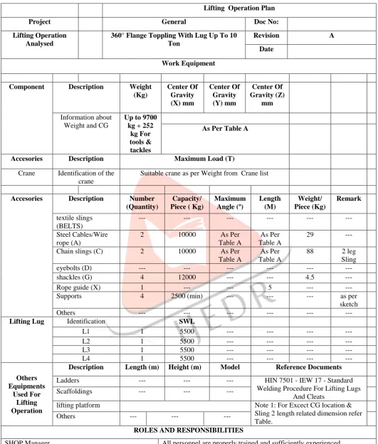
TABLE II OBSERVATION TABLE FOR WORK EQUIPMENTLifting Operation Plan
Project General Doc No:
Lifting Operation Analysed
360° Flange Toppling With Lug Up To 10 Ton
Revision A
Date
Work Equipment
Component Description Weight (Kg) Center Of Gravity (X) mm Center Of Gravity (Y) mm Center Of Gravity (Z) mm Information about Weight and CG
Up to 9700 kg + 252
kg For tools & tackles
As Per Table A
Accesories Description Maximum Load (T)
Crane Identification of the crane
Suitable crane as per Weight from Crane list
Accesories Description Number (Quantity)
Capacity/ Piece ( Kg)
Maximum Angle (º) Length (M) Weight/ Piece (Kg) Remark textile slings (BELTS) --- --- --- --- --- --- Steel Cables/Wire rope (A)
2 10000 As Per
Table A
As Per Table A
29 ---
Chain slings (C) 2 10000 As Per
Table A
As Per Table A
88 2 leg
Sling
eyebolts (D) --- --- --- --- --- ---
shackles (G) 4 12000 --- --- 4.5 ---
Rope guide (X) 1 --- --- 5 --- ---
Supports 4 2500 (min) --- --- --- as per
sketch
Others --- --- --- --- --- ---
Lifting Lug Identification SWL
L1 1 5500 --- --- --- ---
L2 1 5500 --- --- --- ---
L3 1 5500 --- --- --- ---
L4 1 5500 --- --- --- ---
Others Equipments
Used For Lifting Operation
Description Length (m) Height (m) Model Reference Documents
Ladders --- --- --- HIN 7501 - IEW 17 - Standard
Welding Procedure For Lifting Lugs And Cleats
Scaffoldings --- --- ---
lifting platform Note 1: For Excect CG location &
Sling 2 length related dimension refer Table.
Others --- --- ---
ROLES AND RESPONSIBILITIES
SHOP Manager All personnel are properly trained and sufficiently experienced Fabrication/Machine shop /Assembly Manager
Equipment is only operated by trained personnel
Safe equipment is used for the lifting operation and any defective equipment is removed from service
Supply and Care of Rigging Proper rigging equipment is available Fabrication/Machine shop /Assembly Lead
Engineer
IJEDR1402252
International Journal of Engineering Development and Research (www.ijedr.org)2874
Rigging material and equipment are maintained in proper working
condition with necessary color coding & identification tags Supervisor of Rigging Operation Proper rigging of the load
Fabrication/Machine shop /Assembly Supervisor
Supervision of the rigging crew
Ensuring correct assembly of rigging material or equipment as required during the operation, such as the correct installation of lifting bolts . Safety of the rigging crew and other personnel as they are affected by the rigging operation
Establish proper communication procedure / channel Crane Operator
Never put any part of their body under a suspended load Never ride a load while it is being lifted
Riggers
Be aware of suspended loads, signals of the operators and any lifting equipment supports
Use lifting equipment as instructed and report any defects Ensure people are out of the direction of the load
METHOD OF WORK EXECUTION
1. Keep metalic supports which are marked SWL, or standard wooden logs and ensure supports are fixed at destination before it relocated
2. Take tools and tackles to the work location with the help of a trolley 3. Always anchor EYE of Sling in the hook.
4. Secure a guide rope minimum 3Mtrs length to fix lifting tackles in position 5. Secure lifting accessories as per pg 3 & ensure PTW for non routine Lifts.
6. Barricade the area identified for lifting operation, slowly ( micro mode ) lift the job 10 to 15cms to confirm the "CG ." 7. To align the C.G., extend in belt/sling length through bow sackle / turn buckle with above specified capacity.
TABLE II OBSERVATION TABLE FOR SAFE LIFTING Sr no Inner radius Outer Radius CG from Centre Angle 1 Angle 2 Angle 3 X ( In mm)
Y (In mm)
H (In mm)
Tools and Tackles
Main Hook
Auxiliary Hook
1 3500 4000 0 47 90 9 400 3980 8917
WI R E RO P E S L ING , 1 0 T O N, 1 mtr 2 No s. 2 L E G G E D CH AIN S L ING S, 1 0 T o n 5 M trs.
2 3000 4000 0 47 90 9 400 3980 8917
3 2500 4000 0 47 90 9 400 3980 8917
4 2000 4000 0 47 90 9 400 3980 8917
5 1500 4000 0 47 90 9 400 3980 8917
6 1000 4000 0 47 90 9 400 3980 8917
7 500 4000 0 47 90 9 400 3980 8917
8 3000 3500 0 47 88 9 400 3477 7917
9 2500 3500 0 47 88 9 400 3477 7917
10 2000 3500 0 47 88 9 400 3477 7917
11 1500 3500 0 47 88 9 400 3477 7917
12 1000 3500 0 47 88 9 400 3477 7917
IJEDR1402252
International Journal of Engineering Development and Research (www.ijedr.org)2875
14 2500 3000 0 47 73 9 400 2973 6917
15 2000 3000 0 47 73 9 400 2973 6917
16 1500 3000 0 47 73 9 400 2973 6917
17 1000 3000 0 47 73 9 400 2973 6917
18 500 3000 0 47 73 9 400 2973 6917
19 2000 2500 0 47 59 9 400 2468 5917
20 1500 2500 0 47 59 9 400 2468 5917
21 1000 2500 0 47 59 9 400 2468 5917
22 500 2500 0 47 59 9 400 2468 5917
23 1500 2000 0 47 82 15 400 1960 4917
2 L E G G E D CH AIN Sli ng s, 1 0 T o n, 3 M trs.
24 1000 2000 0 47 82 15 400 1960 4917
25 500 2000 0 47 82 15 400 1960 4917
26 1000 1500 0 47 71 23 400 1446 3917
wire Ro pe Sli ng 1 5 T , 2 M trs.
27 500 1500 0 47 71 23 400 1446 3917
28 500 1000 0 47 43 23 400 916.5 2917
Note: all dimensions are in mm unless otherwise specified.
Crane List For Line Item 23 To 28
Location Crane Capacity (Tons) Hook Type Hook Height (m)
BAY 1 60 MH 4.9
BAY 1 10 AH 6
BAY 1 35 MH 5.2
BAY 1 5 AH 5.5
BAY 1 25 MH 5
BAY 1 10 AH 5.7
PLATE
YARD 25 MH 9.5
PLATE
YARD 5 AH 9.7
BAY 2 200 MH 14.9
Crane List For Line Item 1 To 22
Location Crane Capacity (Tons) Hook Type Hook Height (m) PLATE
YARD 25 MH 9.5
PLATE
YARD 5 AH 9.7
BAY 2 200 MH 14.9
BAY 2 10 AH 15.5
BAY 2 200 MH 14.9
BAY 2 50 AH 15
BAY 2 75 MH 14.3
BAY 2 25 AH 14.7
BAY 2 40 MH 11
IJEDR1402252
International Journal of Engineering Development and Research (www.ijedr.org)2876
BAY 2 10 AH 15.5
BAY 2 200 MH 14.9
BAY 2 50 AH 15
BAY 2 75 MH 14.3
BAY 2 25 AH 14.7
BAY 2 40 MH 11
BAY 2 10 AH 11.8
BAY 3 75 MH 14.6
BAY 3 10 AH 15.5
BAY 3 75 MH 14.6
BAY 3 10 AH 15.5
BAY 3 75 MH 14.6
BAY 3 25 AH 14.9
BAY 3 75 MH 14.6
BAY 3 25 AH 14.9
BAY 4 35 MH 5.2
BAY 4 5 AH 5.5
BAY 5 100 MH 9.1
BAY 5 20 AH 9.5
BAY 5 55 MH 9.2
BAY 5 20 AH 9.7
BAY 3 75 MH 14.6
BAY 3 10 AH 15.5
BAY 3 75 MH 14.6
BAY 3 10 AH 15.5
BAY 3 75 MH 14.6
BAY 3 25 AH 14.9
BAY 3 75 MH 14.6
BAY 3 25 AH 14.9
BAY 5 100 MH 9.1
BAY 5 20 AH 9.5
BAY 5 55 MH 9.2
BAY 5 20 AH 9.7
V.CONCLUSION
- The safe lifting operation and it is intended to provide guidance to personnel planning for a lifting operation. A lifting plan should be developed based on the consideration of the factors listed – Machine, Material, Medium, Man and Method. Depending on the complexity of the lifting operation, details to be considered in the Lifting Plan will vary. - The primary objective of the Lifting Plan is to facilitate common understanding amongst the lifting crew for a safe
outcome. The underlying principle is that all foreseeable risks are assessed and eliminated / mitigated.
- In order to provide practical guidance, a template of a Lifting Plan is developed (see Appendix 2). The suggested template addressed key factors affecting safe lifting operations:
Details of the load;
Details of the lifting equipment / lifting gears used;
Means of communications;
Personnel involved in the lifting operation;
Physical and environmental considerations;
Sequence / special precautions;
Sketch of the zone of operation. The Lifting Operation Plan was developed
To reduce the accidents,
To reduce the incidents,
Material losses,
IJEDR1402252
International Journal of Engineering Development and Research (www.ijedr.org)2877
Cost losses.
- Proper procedures are planned for the effective and efficient working of the lifting operation. Following points should be taken care of:-
1. Lifting tools and tackles should be inspected.
2. Lifting machineries like E.O.T crane, Gantry Crane, Hydra Crane, Crawler Crane etc. should also be inspected.
3. Every workers, engineers and supervisors should have proper knowledge of the lifting tools and tackles, its uses, its application, capacity, rejection criteria, etc.
4. The worker, engineers and supervisors should be given step by step training of the lifting operations.
5. Proper training and guidance to worker to understanding the lifting plan and them role and responsibilities and how to Communicate with each other during lifting operation.
VI.ACKNOWLEDGMENT
The authors would like to acknowledge the support for experimental data collection to Site assistants, Site in-charge Mr. Harsh Patel and Director Mr. D. H. Patel from D. H. Patel & Associate Pvt. Ltd., Surat, Gujarat, India.
REFERENCES
[1] Beavers, J.E., Moore, J.R., Rinehart, R., Schriver, W.R., 2005. Report #35-Crane- Related Fatalities in the Construction Industry. Construction Industry Research and Policy Center, University of Tennessee, Knoxville, TN.
[2] Shapira, A., Glascock, J.D., 1996. Culture of using mobile cranes for building construction. Construction Engineering and Management 122 (4), 298.
[3] Neitzel, R.L., Seixas, N.S., Ren, K.K., 2001. A Review of crane safety in the construction industry. Applied Occupational and Environmental Hygiene 16 (12), 1106–1117.
[4] Baybutt, P. (2013a). Analytical methods in process safety management and system safety engineering e process hazards analysis. In J. M. Haight (Ed.), Handbook of loss prevention engineering. Wiley-VCH.
[5] Baybutt, P. (2013b). Analytical methods in process safety management and system safety engineering e layers of protection analysis. In J. M. Haight (Ed.), Handbook of loss prevention engineering. Wiley-VCH.
[6] Baybutt, P. (2002). Layers of protection analysis for human factors (LOPA-HF). Process Safety Progress, 21(2), 119e129.
[7] Baybutt, P. (2007). Chapter 26, Qualitative hazard analysis. In D. Crowl (Ed.), Human factors methods for improving performance in the process industries. New York, NY: Center for Chemical Process Safety, American Institute of Chemical Engineers.
[8] CFR. (1992). Final rule, process safety management (PSM) of highly hazardous chemicals, 29 CFR 1910.119. Federal Register, 57(36), 6355e6417.
[9] Baybutt, P. (2002). Layers of protection analysis for human factors (LOPA-HF). Process Safety Progress, 21(2), 119e129.
[10] Attwood, D. A., Deeb, J. M., & Danz-Reece, M. E. (2004). Ergonomic solutions for the process industries. Oxford, UK: Gulf Professional Publishing.