Power Management Based on Hybrid Energy
Storage System
Dr.S.Deepa1, Faaizah Banu.R2, Hemalatha.K3 , Keerthana.B4, Kayalarasi.J5
Professor, Dept. of EEE, Panimalar Institute of Technology, Chennai, Tamil nadu, India1
UG Student, Dept. of EEE, Panimalar Institute of Technology, Chennai, Tamil nadu, India2
UG Student, Dept. of EEE, Panimalar Institute of Technology, Chennai, Tamil nadu, India3
UG Student, Dept. of EEE, Panimalar Institute of Technology, Chennai, Tamil nadu, India4
UG Student, Dept. of EEE, Panimalar Institute of Technology, Chennai, Tamil nadu, India5
ABSTRACT: This paper proposes a supervisory power management system (PMS) for a grid interactive microgrid with a hybrid energy storage system. The key feature of the proposed PMS is reduced number of sensors required to implement the PMS. The PMS considers renewable power variation, grid availability, electricity pricing and changes in local loads. It can detect the operating mode of system without measuring load currents and powers. A single phase voltage source converter transfers real power between DC grid and utility grid besides offering ancillary services such as harmonic mitigation, reactive power support and unity power factor at the point of common coupling. In the proposed system, a better DC link voltage regulation is achieved and the usage of super capacitors reduces the current stress on battery the battery. The PMS also addresses extreme operating conditions such as load shedding, off-maximum power point tracking operation of PV, elimination of critical oscillation of HESS powers, islanded operation and resynchronization with grid. The performance of the proposed PMS is verified by digital simulation and experimental studies.
KEYWORDS: Power management system, HESS, PMA
I.INTRODUCTION
The increasing demand for energy efficient appliances is promoting the use of DC appliances in residential and commercial sectors. DC appliances like LED lighting and inverter driven appliances like refrigirators, air conditioners . At the same time, renewable energy based distribution system is encouraging the use of DC appliances to minimize conversion losses .Therefore, both AC and DC loads will co-exist in renewable-grid integrated distribution system. When renewable energy sources contribute an important portion of power generation, their irregular and random output variations can bring uncertainties in power system planning .
The renewable power generation technology, which consists of PV and storage systems is required to ensure controllability, reliability and stability of overall system. Generally, hybrid energy storage systems like battery and supercapacitor in microgrids to improve reliability and life cycle of the system. The high power density of supercapacitor increases the life cycle of battery .
In a microgrid with HESS, meeting the load demand by maintaining battery and supercapacitor within limits is an important due to the uncertainties in Renewable energy system power. In this work, it is assumed that the microgrid is always connected to the utility grid. Also, the supercapacitor doesn’t absorb the transients when the battery reference current is set to zero which increases the rate of change of battery current. This is due to the fact that the EMS changes the battery reference current instantly from zero to reference value during battery mode changes i.e., idle to charging mode / discharging mode and vice-versa. As a result, the battery is forced to respond quickly .
II POWER MANAGEMENTALGORITHM (PMA):
The PMA decides the operating mode of the system based on average current. The PMA is formulated with following operational objectives. (i) To identify the operating mode of the system and make decisions based on average current,(ii) To achieve power balance in every operating mode, (iii) To maintain Battery and supercapacitor within limits and to eliminate current oscillation of HESS at the edge of supercapacitor, (iv) To supply average power by battery only if the system is islanded, (v) To supply oscillating and transient peak powers by supercapacitor only, (vi) to minimize/maximize power drawn/supplied from/to grid during peak pricing and (vii) To provide minimum backup for critical loads in islanded mode.
There are three operating modes of the system, namely (A) Deficit power mode (DPM)
(B) Floating power mode (FPM) (C) Excess power mode (EPM).
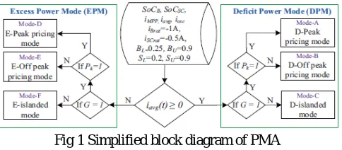
Fig 1 Simplified block diagram of PMA
In both modes of operation, there are three sub-modes based on the availability of grid and peak pricing status .They are (i) Peak pricing mode (ii) Off-peak pricing mode (iii) Islanded mode.
In each sub-mode, SoCB and SoCSC are monitored and maintained within limits. If grid power pricing is high then Pk is set to high (1), else set to low (0). Similarly, when the system is connected to grid then G is set to high (1), else set to low (0). A rule based control is developed to implement the PMA. The algorithm is initialized with battery SoC lower limit BL and upper limit BU are set to 0.25 and 0.9 respectively and supercapacitor lower limit SL and upper limit SU are set to 0.2 and 0.9 respectively.
(A) DEFICIT POWER MODE:
In DPM, the average current is greater than or equal to zero and there are three sub-modes explained as following.
ModeA: D-peak pricing mode
In this mode, grid is on and peak pricing is enabled i.e., G = 1, Pk = 1. The deficit power is drawn from grid while charging battery and supercapacitor upto 50% of their capacity by updating BL = 0.5 and SL = 0.5. There are four possible cases depending on SoCB and SoCSC. In those four cases, battery and supercapacitor are charged if their SoCs are less than their respective lower limits, else battery will be idle and supercapacitor supplies transient and oscillating powers.
ModeB: D-off peak pricing mode
In this mode, grid is on and peak pricing is disabled i.e., G = 1, Pk = 0. As the grid power pricing is less, the deficit power is drawn from grid while charging battery and super capacitor upto 90% of their capacity by updating BU = 0.9 and SU = 0.9.
ModeC: D-islanded mode
(B) EXCESS POWER MODE:
In EPM, the average current is less than zero and there are three sub-modes explained as following.
ModeD: E-peak pricing mode
In this mode, grid is on and peak pricing is enabled i.e., G = 1, Pk = 1. Therefore, maximum possible amount of excess power is injected into the grid by limiting battery and supercapacitor charging up to 50% of their capacity by updating BL = 0.5 and SL = 0.5. As the power is injected into the grid, it is referred as grid injecting mode.
ModeE: E-off peak pricing mode
In this mode, grid is on and peak pricing is disabled i.e., G = 1, Pk = 0. Therefore, the excess power is preferred to charge battery and supercapacitor upto 90% of their capacity by updating BU = 0.9 and SU = 0.9 as the pricing of power injected into the grid is less. Once the battery and supercapacitor are fully charged, the excess power is injected into grid.
ModeF: E-islanded mode
In this mode, grid is off i.e., G = 0. Therefore, the excess power has to be absorbed by HESS or the PV power should be controlled such that it is equal to load power.
III.PROPOSED METHOD
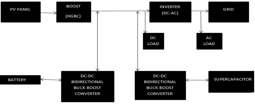
The block diagram of the proposed method is shown in figure 2.It consists of four main units. They are (i) Photovoltaic Inverter (ii) Power Management System (iii)Super capacitor Units and (iv) Renewable Energy system.
Figure 2 Block diagram of proposed method
(A) Photovoltaic Inverter :A solar inverter, or converter or PV inverter, converts the variable direct current (DC) output of a photovoltaic (PV) solar panel into a utility frequency alternating current (AC) that can be fed into a commercial electrical grid or used by a local, off-grid electrical network.It is a critical balance of system (BOS)– component in a photovoltaic system, allowing the use of ordinary AC-powered equipment Solar power inverters have special functions adapted for use with photovoltaic arrays, including maximum power point tracking and anti-islanding protection.
(B) Power Management System : A Power Management System is a modular unit, which combines Static Voltage
utility for other applications as well where a controlled power is required for electrical appliances at industrial sites, manufacturing facilities.
(C)Super capacitor Units :A Super capacitor (SC) is a high-capacity capacitor with capacitance values much higher
than other capacitors that bridge the gap between electrolytic capacitors and rechargeable batteries.Because, Supercapacitors operate without forming chemical bonds current loads, including charge, discharge and peak currents are not limited by reaction constraints.Current load and cycle stability can be much higher than for rechargeable batteries. Current loads are limited only by internal resistance, which may be substantially lower than for batteries.
(D) Renewable Energy System :A solar panel is a packaged, interconnected assembly of solar cells, also known as
photovoltaic cells. The solar panel can be used as a component of a larger photovoltaic system to generate and supply electricity in commercial and residential applications. A photovoltaic system typically includes an array of solar panels, an inverter, and sometimes a battery and interconnection wiring. Solar panels use light energy from the sun to generate electricity through the photovoltaic effect.
The structural member of a module can either be the top layer or the back layer. The majority of modules use wafer-based crystalline silicon cells or thin-film cells wafer-based on cadmium telluride or silicon. The conducting wires that take the current off the axels may contain silver, copper or other conductive transition metals.
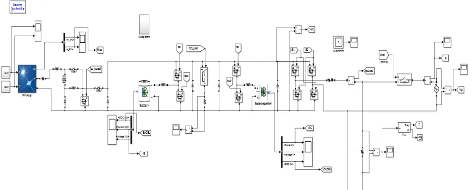
The simulation circuit of the proposed method is shown in figure 3.
IV. RESULT AND DISCUSSION
The high gain boost convertor( HGBC) Voltage and Current Wave Form is shown in figure 4
Figure 4 HGBC Voltage and Current Wave Form
The above graph shows the output voltage and output current of high gain boost convertor (DC-DC). The voltage produced by solar panel is 12 v, this can be boosted upto 100v with the help of high gain boost converter(DC-DC).This boosted output is given to the inverter(DC-AC) and the DC load .The inverter converts the dc voltage into the ac voltage and it is given to the grid.
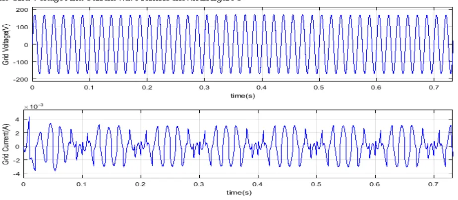
The Grid Voltage And Current wave form is shown in figure 5
Figure.5 Grid voltage and current waveform
In Mode C i.e., deficit islanded mode, the grid voltage is decreased to zero. The PMA detects the disturbance and islands the microgrid by activating the grid relay. As the SoCB is more than 0.5, AC loads are supplied power by restoring voltage on AC side of VSC .The islanding of micro grid is achieved in 20 ms which can be observed. At this instant, the utility grid voltage is restored. The PMA detects the grid voltage restoration and closes the relay .It can be noticed that the AC loads are off from SoCB is less than 0.5 in islanded mode.
In Mode F i.e., excess islanded mode, at this instant both SoCB and SoCSC are set to 0.95 which is higher than their upper limits (0.9) and iMPP is increased to 6 A. This forces the system to operate in off-MPPT mode and ipv decreases to 3 A as illustrated . It can be noticed that the DC load is increased by 100% , due to which ipv increases from 3A to 5A. At this instant the DC load is decreased to 50%, due to which ipv decreases from 5A to 3A. It can be noticed that due to battery current smoothing, the rate of change of battery current and peak overshoot of vdc are decreased to 0.93A/s and 2V respectively compared to that of 1.8 A/s and 5.2V .
V. CONCLUSION
A unified power management scheme is proposed for a grid interactive hybrid microgrid with HESS. The new method of identifying microgrid operating mode is proposed and verified in all possible operating modes. The formulated PMS addresses the possible operating modes of the microgrid and achieves stable and desirable performance. It is shown that the proposed PMS ensures reliable and continuous power supply to the local loads and enables the bidirectional real power transfer between the microgrid and the utility grid while improving the power quality aspects at the PCC. Various features like fast DC link voltage regulation, reduced battery current stresses, Off-MPPT operation are illustrated. The proposed PMS achieves seamless mode transfer using supercapacitor units. The power quality at the point of common coupling is maintained as per the grid standards. Also, the proposed PMS does not require forecasting of weather and measurement load currents / powers, which reduces the complexity and number of sensors.
REFERENCES
[1] O. Lucia, I. Cvetkovic, H. Sarnago, D. Boroyevich, P. Mattavelli, and F. Lee, “Design of home appliances for a dc-based nanogrid system: An induction range study case,” IEEE J. Emerg. Sel.Topics Power Electron., vol. 1, no. 4, pp. 315–326, Dec 2013.
[2] F. Nejabatkhah and Y. W. Li, “Overview of power management strategies of hybrid ac/dc microgrid,” IEEE Trans. Power Electron., vol. 30, no. 12, pp. 7072–7089, Dec 2015.
[3] P. Denholm, R. Margolis, T. Mai, G. Brinkman, E. Drury, M. Hand, and M. Mowers, “Bright future: Solar power as a major contributor to the u.s. grid,” IEEE Power and Energy Mag., vol. 11, no. 2, pp. 22–32, March 2013.
[4] S.-T. Kim, S. Bae, Y. C. Kang, and J.-W. Park, “Energy management based on the photovoltaic hpcs with an energy storage device,” IEEE Trans. Ind. Electron., vol. 62, no. 7, pp. 4608–4617, July 2015.
[5] C. Abbey and G. Joos, “Super capacitor energy storage for wind energy applications,” IEEE Trans. Ind. Applic., vol. 43, no. 3, pp. 769–776, May 2007.
[6] N.R.Tummuru, M.K.Mishra and S.Srinivas, “Dynamic energy management of renewable grid integrated hybrid energy storage system,”IEEE Trans.Ind.Electron., vol.62, no.12, pp.7728–7737, Dec 2015.
[7] G. Wang, M. Ciobotaru, and V. Agelidis, “Power smoothing of large solar pv plant using hybrid energy storage,” IEEE Trans. Sustain. Energy, vol. 5, no. 3, pp. 834–842, July 2014.
[8] B. Indu Rani, G. Saravana Ilango, and C. Nagamani, “Control strategy for power flow management in a pv system supplying dc loads,” IEEE Trans. Ind. Electron., vol. 60, no. 8, pp. 3185–3194, Aug 2013.
[9] Y.-M.Chen, H.-C.Wu, Y.-C.Chen, K.-Y.Lee, and S.-S. Shyu, “The ac line current regulation strategy for the grid-connected pv system,” IEEE Trans. Power Electron., vol. 25, no. 1, pp. 209–218, Jan 2010.
[10] F. Savoye, P. Venet, M. Millet, and J. Groot, “Impact of periodic current pulses on li-ion battery performance,” IEEE Trans. Ind. Electron., vol. 59, no. 9, pp. 3481–3488, Sept 2012.
[11] L. Chen and S. Mei, “An integrated control and protection system for photovoltaic microgrids,” CSEE Journal of Power and Energy Systems, vol. 1, no. 1, pp. 36–42, March 2015.
[12] D. Wang and F. Z. Peng, “Smart gateway grid: A dg-based residential electric power supply system,” IEEE Trans. Smart Grid, vol. 3, no. 4 pp. 2232–2239, Dec 2012.