ISSN (Print) : 2320 – 3765 ISSN (Online): 2278 – 8875
I
nternational
J
ournal of
A
dvanced
R
esearch in
E
lectrical,
E
lectronics and
I
nstrumentation
E
ngineering
(A High Impact Factor, Monthly, Peer Reviewed Journal)
Website: www.ijareeie.com
Vol. 8, Issue 11, November 2019
LMMN Based Adaptive Control Method and
ANN Based MPPT Method for Grid Tied
Wind-PV System
V.Anbulakshmi, G.Suriya Priya, M.E,Ph.D, Dr.K.Punitha M.E,Ph.D.,
PG Scholar, Dept. of EEE, P.S.R.Rengasamy College of Engineering, Sivakasi, Tamilnadu, India
Assistant Professor, Dept. of EEE, P.S.R.Rengasamy College of Engineering, Sivakasi, Tamilnadu, India
Head of the Dept, Dept. of EEE, P.S.R.Rengasamy College of Engineering, Sivakasi, Tamilnadu, India
ABSTRACT: A new topology comprising of wind turbine driven by Doubly Fed Induction Generator and solar photovoltaic (PV) array for renewable energy is proposed in this work .The inputs for the proposed system parameters such as variable wind speed solar insolation. The project is energy management system for micro grid using Hybrid energy systems. The speed variations are absorbed by back to back converter. The converters are Utility Grid side Converter (UGC) and Generator side Converter (GC) with a common dc link, the solar PV arrays is connecting directly. In order to maintain constant voltage to the DC grid using Landsman converter with Artificial Neural Network based MPPT algorithm. To achieve grid synchronization using hysteresis current controller. PV arrays are connected to the DC bus through Landsman converter to simulate DC sources. The results of PV system using the LMMN based adaptive control method integrating the ANN based MPPT method. A DFIG wind generation system is connected to AC bus to simulate AC sources. A battery with bidirectional DC/DC converter is connected to DC bus as energy storage.
KEYWORDS: Utility grid, PV, Wind, DFIG, UGC, GC, LMMN control.
I. INTRODUCTION
The ever-growing energy demand and emphasis on clean energy have solar and wind based renewable power generations system. Between solar and wind energy systems, the solar energy systems are widely found at distribution level as they require little or no maintenance and the solar panels can be installed on almost any roof, as well as on the ground. Therefore, many households and commercial places are being powered by solar power [1]. The solar power generating systems make use of power electronics based dc-dc and dc-ac converters to transform the dc voltage generated by the solar panels into an usable ac voltage [2]. The power electronic converters are controlled to operate the solar panels at maximum power points.
ISSN (Print) : 2320 – 3765 ISSN (Online): 2278 – 8875
I
nternational
J
ournal of
A
dvanced
R
esearch in
E
lectrical,
E
lectronics and
I
nstrumentation
E
ngineering
(A High Impact Factor, Monthly, Peer Reviewed Journal)
Website: www.ijareeie.com
Vol. 8, Issue 11, November 2019
the system efficiency double. The current implementation of microgrid incorporates sources with loads, permits for intentional islanding and use available waste heat of power generation systems [6].
Integration of wind turbines and photovoltaic systems with grid leads to grid instability. One of the solutions to this problem can be achieved by the implementation of microgrid. Even though there are several advantages associated with microgrid operation, there are high transmission line losses. In a microgrid there are several units which can be utilized in a house or country. In a house renewable energy resources and storage devices are connected to DC bus with different converter topology from which DC loads can get power supply. Inverters are implemented for power transfer between AC and DC buses. Common and sensitive loads are connected to AC bus having different coupling points. During fault in the utility grid microgrid operates in islanded mode. If in any case renewable source can’t supply enough power and state of charge of storage devices are low microgrid disconnects common loads and supply power to the sensitive loads [7]-[8]. The vector control technique use for the speed control of DFIG. The vector control technique requires the elements of rotor speed and position. These are estimated by using sensor based or sensorlss based techniques. The use of sensorless technique has reduce the complexity and enhances the system reliability [9]-[11]. The nonlinear voltage current characteristics of the solar PV array has need for the MPPT. The various MPPT techniques can be perturb and observe method (P&O), Incremental conductance maethod (IC), Voltage based peak power, Current based peak power, and the other soft computing techniques are Fuzzy logic control (FLC), Artificial neural network (ANN), Genetic algorithm (GA), Particle swarm optimization (PSO) [12-13].
The adaptive filtering methods are Least Mean Square (LMS) and Least Mean Fourth (LMF) Perturb and Observe method of MPPT (Maximum Power Point Tracking) integrated with the LMS based control technique the drawback of the steady state performance is not attained and it has the low signal to noise ratio. The LMS technique act as a lower order adaptive filter. The least mean fourth based control technique has high signal to noise ratio. The LMF technique act as a higher adaptive filter. The higher order adaptive filter with the Mean Square Error (MSE) has less compared to the lower order adaptive filter [14]-[15]. The above issues are overcome by using the method of least mean mixed norm (LMMN). The LMMN control technique by using the proposed work. The LMMN control technique has lesser MSE resulting in reduced misadjustment. use appilcabel in harmonic compensation.[16]
This work proposes a grid intertie of wind PV system. A wind turbine driven by a DFIG is used for harnessing of wind energy. The solar PV array is connecting directly on the DC link. The benefits are less no of components, reduce the losses, high efficiency and provides the better utilization of power. The control schemes are power electronic converters used in utility grid side converter and the generator side converter. The back to back power electronic converters are used in doubly fed induction generator which controls the grid and rotor currents. The grid side converter is used to regulate the voltage of the DC capacitor. A LMMN based adaptive control is used for load current extraction. The ANN based MPPT is used for optimum power extraction from the solar PV array. The salient features of implemented system, are as follows
.The variable speed of a three phase grid intertie wind - PV systems are increase the power generation. Total Harmonic Distortion is maintained successfully in the grid current with in 5% as the IEEE-519 standard. The Power converter control technique, grid side converter control LMMN control technique are effectively
implemented.
II. SYSTEM CONFIGURATION
ISSN (Print) : 2320 – 3765 ISSN (Online): 2278 – 8875
I
nternational
J
ournal of
A
dvanced
R
esearch in
E
lectrical,
E
lectronics and
I
nstrumentation
E
ngineering
(A High Impact Factor, Monthly, Peer Reviewed Journal)
Website: www.ijareeie.com
Vol. 8, Issue 11, November 2019
A wind generation system consists of doubly fed induction generator with back to back AC/DC/AC PWM converter connected between the rotor through slip rings and AC bus. The AC and DC buses are coupled through a three phase transformer and a main bidirectional power flow converter to exchange power between DC and AC sides. The transformer helps to step up the AC voltage of the main converter to utility voltage level and to isolate AC and DC grids.
MODELING OF PV CELL
The photovoltaic system converts sunlight directly to electricity without having any disastrous effect on our environment. The basic segment of PV array is PV cell, which is just a simple p-n junction device. The fig.4.4 manifests the equivalent circuit of PV cell. Equivalent circuit has a current source (photocurrent), a diode parallel to it, a resistor in series describing an internal resistance to the flow of current and a shunt resistance which expresses a leakage current. The current supplied to the load can be given as.
Where
IPV–Photocurrent current,
IO–diode’s Reverse saturation current, V–Voltage across the diode,
a– Ideality factor VT –Thermal voltage Rs– Series resistance Rp–Shunt resistance
DFIG PWM
ISSN (Print) : 2320 – 3765 ISSN (Online): 2278 – 8875
I
nternational
J
ournal of
A
dvanced
R
esearch in
E
lectrical,
E
lectronics and
I
nstrumentation
E
ngineering
(A High Impact Factor, Monthly, Peer Reviewed Journal)
Website: www.ijareeie.com
Vol. 8, Issue 11, November 2019
Fig 4.4 Equivalent circuit of Single diode modal of a solar cell
PV cell photocurrent, which depends on the radiation and temperature, can be expressed as.
Where
KI– cell’s short circuit current temperature coefficient G–solar irradiation in W/m3
GSTC–nominal solar irradiation in W/m3
IPV_STC– Light generated current under standard test condition
The reverse saturation current varies as a cubic function of temperature, which is represented as
Where
I0_STC– Nominal saturation current Eg – Energy band gap of semiconductor TSTC–temperature at standard test condition q – Charge of electrons
The reverse saturation current can be further improved as a function of temperature as follows
Where,
ISC_STC– short circuit current at standard test condition VOC_STC– short circuit voltage at standard test condition KV– temperature coefficient of open circuit voltage
Many authors proposed more developed models for better accuracy and for different purposes. In some of the models, the effect of the recombination of carriers is represented by an extra diode. Some authors also used three diode models which included influences of some other effects that are not considered in previous models. But due to simplicity we use single diode model for our work. Efficiency of a PV cell does not depend on the variation in the shunt resistance Rp of the cell but efficiency of a PV cell greatly depends on the variation in series resistance Rs. As Rp of the cell is inversely proportional to the shunt leakage current to ground so it can be assumed to be very large value for a very small leakage current to ground. As the total power generated by a single PV cell is very low, we used a combination of PV cells to fulfill our desired requirement. This grid of PV cells is knows as PV array. The equations of the PV array can be represented as
ISSN (Print) : 2320 – 3765 ISSN (Online): 2278 – 8875
I
nternational
J
ournal of
A
dvanced
R
esearch in
E
lectrical,
E
lectronics and
I
nstrumentation
E
ngineering
(A High Impact Factor, Monthly, Peer Reviewed Journal)
Website: www.ijareeie.com
Vol. 8, Issue 11, November 2019
NP– Number of parallel cells MODELING OF WIND TURBINE
The aerodynamic power of wind is converted into mechanical energy by wind turbine i.e. the blades obtain kinetic energy from the wind which is transformed to mechanical torque at the rotor shaft of the wind turbine. The wind power can be calculated by the following equation
Pt=1/2ρCpAV3 (1) Where
P
tis the rotor mechanical power (W) V the wind speed (m/s)
Α= π R2 the rotor surface (m 2
) R is the rotor radius (m)
ρ the air density (kg/m3) Cp is the power coefficient.
The rotor aerodynamic power coefficient, C
p, is the function of blade pitch angle (β) and tip speed ration (λ) λ= Tip speed/Wind speed
λ=ωrR/V (2) Sub eqn (2) in (1) we get
Pt = 1\2 Cp (λ)ρA(R/λ)3ω3
The output torque of the wind turbine Tt is calculated by the following equation Tt = 1/2 ρCpA(V/λ)
Variable speed turbines are made to capture the maximum energy of the wind by operating them at a blade speed that gives the optimum tip speed ratio. This may be done by changing the speed of the turbine in proportion to the change in wind speed. The variable speed operation will allow a wind turbine to capture more energy from the wind.
III. CONTROL STRATEGY
The proposed PV-Wind hybrid system implements two appropriate control techniques for grid side and generator side control. The presented system works efficiency under variable wind velocity and changing solar insolation. The control techniques for discussed in below section.
Generator side control technique. Grid side control technique.
POWER CONVERTER CONTROL
A device that converts dc power into ac power at desired output voltage and frequency is called an Inverter. Voltage Source Inverter is one in which the dc source has small or negligible impedance. In other words, a voltage source inverter has a stiff voltage source at its input terminals. AC loads may require constant or adjustable voltage at their input terminals. When such loads are fed by inverters, it is essential that output voltage of the inverters is so controlled as to fulfill the requirements of the ac loads. PWM control is a method to control the output voltage that is widely in application. In this method, a fixed dc input voltage is given to the inverter and a controlled ac output voltage is obtained by adjusting the on and off periods of the inverter components. The advantages possessed by PWM technique are as under, The output voltage control with this method can be obtained without any additional components. With this method, lower order harmonics can be eliminated or minimized along with its output voltage
ISSN (Print) : 2320 – 3765 ISSN (Online): 2278 – 8875
I
nternational
J
ournal of
A
dvanced
R
esearch in
E
lectrical,
E
lectronics and
I
nstrumentation
E
ngineering
(A High Impact Factor, Monthly, Peer Reviewed Journal)
Website: www.ijareeie.com
Vol. 8, Issue 11, November 2019
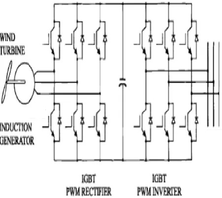
Fig IGBT based rectifier and inverter
As the higher order harmonics can be filtered easily, the filtering requirements are minimized. The Insulated Gate Bipolar Transistor (IGBT) is a three-terminal power semiconductor device, noted for high efficiency and fast switching. Since it is designed to rapidly turn on and off, amplifiers that use it often synthesize complex waveforms with pulse width modulation and low pass filters. Back-to-back voltage source convertor is used in doubly fed induction generator which controls the grid and rotor currents. By controlling the rotor currents by the converter it is possible to adjust the active and reactive power fed to the grid from the stator independently of the generators turning speed. Rotor circuit is controlled by a power electronics converter, the induction generator is able to both import and export reactive power.
GRID SIDE CONVERTER CONTROL
The grid-side controller the d-axis of the rotating reference frame used for d-q transformation is aligned with the positive sequence of grid voltage. This controller consists of
1. A measurement system measuring the d and q components of AC currents to be controlled as well as the sDC voltage Vdc.
2. An outer regulation loop consisting of a DC voltage Regulator. 3. An inner current regulation loop consisting of a current Regulator.
ISSN (Print) : 2320 – 3765 ISSN (Online): 2278 – 8875
I
nternational
J
ournal of
A
dvanced
R
esearch in
E
lectrical,
E
lectronics and
I
nstrumentation
E
ngineering
(A High Impact Factor, Monthly, Peer Reviewed Journal)
Website: www.ijareeie.com
Vol. 8, Issue 11, November 2019
Figure 6.2 Grid side converter control
LMMN CONTROL
The PV utilizes the LMMN adaptive control algorithm. LMMN corresponds to a new family of stochastic gradient adaptive filter algorithms based on mixed error norms. The LMMN method has combined the benefits of Least Mean Square and Least Mean Fourth technique . The performance of least mean square (LMS) is unstable in low signal-to-noise ratio (SNR) region and has more sensitive to signal-to-noise . On the contrary, least mean fourth (LMF) algorithm is better convergence and it has difficult to implement in practical system because of its high computational complexity in high SNR region and lesser noise in weights
The LMMN algorithm operates by minimizing a cost function which is the convex combination of the squared and fourth powers of the error norms .
J(k) = λE {e(k)2} +(1− λ)E{ e(k)4} Where,
λ =[0,1] mixing parameter.
E = Mathematical expectation operator e = error adaptive component
k = sample index in time
The performance of LMMN algorithm is simple and faster than LMS and LMF. It has lower Mean Square Error which leads to quick convergence.
IV. SIMULATION RESULTS
ISSN (Print) : 2320 – 3765 ISSN (Online): 2278 – 8875
I
nternational
J
ournal of
A
dvanced
R
esearch in
E
lectrical,
E
lectronics and
I
nstrumentation
E
ngineering
(A High Impact Factor, Monthly, Peer Reviewed Journal)
Website: www.ijareeie.com
Vol. 8, Issue 11, November 2019
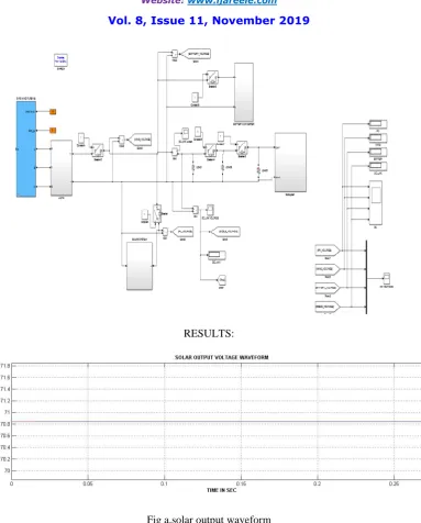
RESULTS:
Fig a.solar output waveform
ISSN (Print) : 2320 – 3765 ISSN (Online): 2278 – 8875
I
nternational
J
ournal of
A
dvanced
R
esearch in
E
lectrical,
E
lectronics and
I
nstrumentation
E
ngineering
(A High Impact Factor, Monthly, Peer Reviewed Journal)
Website: www.ijareeie.com
Vol. 8, Issue 11, November 2019
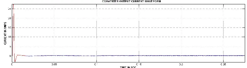
Fig c. Landsman converter input current waveform
Fig d. Landsman converter output voltage waveform
Fig e. Landsman converter output current waveform
ISSN (Print) : 2320 – 3765 ISSN (Online): 2278 – 8875
I
nternational
J
ournal of
A
dvanced
R
esearch in
E
lectrical,
E
lectronics and
I
nstrumentation
E
ngineering
(A High Impact Factor, Monthly, Peer Reviewed Journal)
Website: www.ijareeie.com
Vol. 8, Issue 11, November 2019
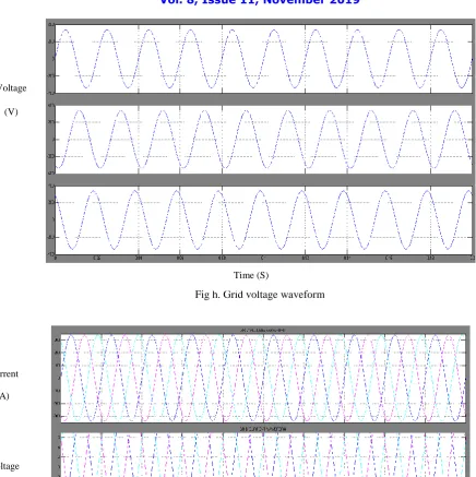
Fig f. Output voltage waveform in DFIG
Fig g. Grid current waveform
Current
(A)
ISSN (Print) : 2320 – 3765 ISSN (Online): 2278 – 8875
I
nternational
J
ournal of
A
dvanced
R
esearch in
E
lectrical,
E
lectronics and
I
nstrumentation
E
ngineering
(A High Impact Factor, Monthly, Peer Reviewed Journal)
Website: www.ijareeie.com
Vol. 8, Issue 11, November 2019
Fig h. Grid voltage waveform
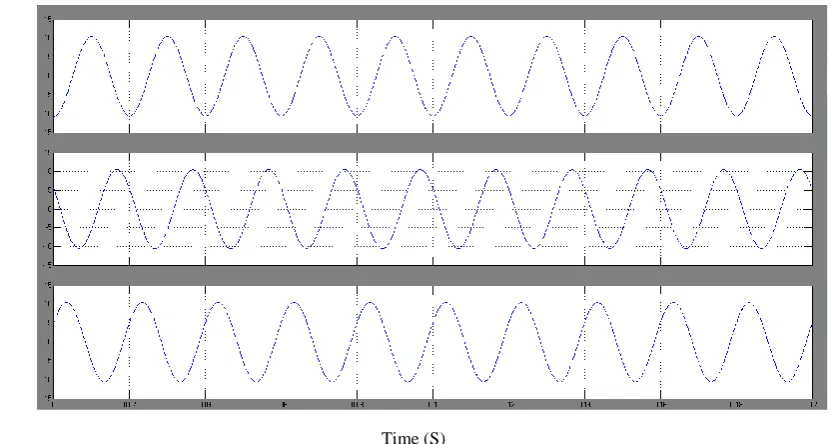
Fig i. Three phase grid voltage and current waveform
The above figure shows the performance of grid. The figures are represented in g. Grid current waveform, h. Grid
Voltage
(V)
Time (S)
Current
(A)
Voltage
(V)
ISSN (Print) : 2320 – 3765 ISSN (Online): 2278 – 8875
I
nternational
J
ournal of
A
dvanced
R
esearch in
E
lectrical,
E
lectronics and
I
nstrumentation
E
ngineering
(A High Impact Factor, Monthly, Peer Reviewed Journal)
Website: www.ijareeie.com
Vol. 8, Issue 11, November 2019
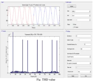
Fig THD value
The above figure shows that the Totsl Harmonic Distortion value.
V. CONCLUSION
The modelling of hybrid micro grid for power system configuration is done in MATLAB/SIMULINK environment. The present work mainly includes the grid tied mode of operation of hybrid grid. The models are developed for all the converters to maintain stable system under various loads and resource conditions and also the control mechanism are studied. MPPT ANN algorithm is used to harness maximum power from DC sources and to coordinate the power exchange between DC and AC grid. Although the hybrid grid can diminish the processes of DC/AC and AC/DC conversions in an individual AC or DC grid, there are many practical problems for the implementation of the hybrid grid based on the current AC dominated infrastructure. The efficiency of the total system depends on the diminution of conversion losses and the increase for an extra DC link. The hybrid grid can provide a reliable, high quality and more efficient power to consumer. The hybrid grid may be feasible for small isolated industrial plants with both PV systems and wind turbine generator as the major power supply.
REFERENCES
[1] B. Liu, L. Wang, D. Song, M. Su, J. Yang, D. He, Z. Chen, and S. Song, “Control of single-phase grid-connected photovoltaic inverter under battery input condition in residential photovoltaic/battery systems,” IEEE Transactions on Sustainable Energy, vol. Early Access, pp. 1–1, 2018. [2] F. Blaabjerg, Z. Chen, and S. B. Kjaer, “Power electronics as efficient
interface in dispersed power generation systems,” IEEE Transactions on Power Electronics, vol. 19, no. 5, pp. 1184–1194, Sept 2004.
[3] S. Bose, Y. Liu, K. Bahei-Eldin, J.de Bedout, and M. Adamiak, “Tie line Controls in Microgrid Applications,” in iREP Symposium Bulk Power System Dynamics and Control VII, Revitalizing Operational Reliability, pp. 1-9, Aug. 2007.
[4] R. H. Lasseter, “MicroGrids,” in Proc. IEEE-PES’02, pp. 305-308, 2002
[5] Michael Angelo Pedrasa and Ted Spooner, “A Survey of Techniques Used to Control Microgrid Generation and Storage during Island Operation,” in AUPEC, 2006.
ISSN (Print) : 2320 – 3765 ISSN (Online): 2278 – 8875
I
nternational
J
ournal of
A
dvanced
R
esearch in
E
lectrical,
E
lectronics and
I
nstrumentation
E
ngineering
(A High Impact Factor, Monthly, Peer Reviewed Journal)
Website: www.ijareeie.com
Vol. 8, Issue 11, November 2019
[7] Zhenhua Jiang, and Xunwei Yu, “Hybrid DC- and AC-Linked Microgrids: Towards Integration of Distributed Energy Resources,” in IEEE Energy2030 Conf., pp.1-8, 2008
[8] F. Katiraei and M. R. Iravani, “Power Management Strategies for a Microgrid with Multiple Distributed Generation Units,” IEEE trans. Power System, vol. 21, no. 4, Nov. 2006.
S[9] P. Piagi and R. H. Lasseter, “Autonomous control of microgrids,” in Proc. IEEE-PES’06, 2006, IEEE, 2006.
[10] A. K. Jain and V. T. Ranganathan, “Modeling and field oriented control of salient pole wound field synchronous machine in stator flux coordinates,” IEEE Trans. Ind. Elect., vol. 58, no. 3, pp. 960-970, March 2011.
[11] I.Bolda, “control issues in adjustable speed derives,” IEEE.Ind.Elect.Magazine,col.2,no3,pp.35-50,2008.
[12] T. Esram, J. W. Kimball, P. T. Krein, P. L. Chapman and P. Midya, “Dynamic maximum power point tracking of photovoltaic arrays using ripple correlation control,” IEEE Trans. on Pow. Elec., vol. 21, no. 5, pp. 1282-1291, Sept. 2006.
[13] A. Ramyar, H. Iman-Eini and S. Farhangi, “Global Maximum Power Point Tracking Method for Photovoltaic Arrays Under Partial Shading Conditions,” IEEE Trans. Ind. Elect., vol. 64, no. 4, pp. 2855-2864, April 2017.
[14] G. Gui, W. Peng, and F. Adachi, “Adaptive system identification using robust LMS/F algorithm,” Int. Jou. Com. Syst., vol. 27, pp. 2956–2963, 2014.
[15]R. K. Agarwal, I. Hussain and B. Singh, “LMF-based control algorithm for single stage three-phase grid integrated solar PV system,” IEEE Trans. Sust. Energy, vol. 7, no. 4, pp. 1379-1387, Oct. 2016.
[16] A. Zerguine, C. F. N. Cowan and M. Bettayeb, “Adaptive echo cancellation using least mean mixed-norm algorithm,” IEEE Trans. Sig. Process., vol. 45, no. 5, pp. 1340-1343, May 1997.
[17]A.Bubshait, A.Molezaei, M.G.Simoes, T.D.C.Busarello “Power quality enhancement for a Grid connected wind turbine energy system” IEEE Trans.Ind. App,.Vol.53,no.3,pp.2495-2025, May-June 2017.
[18] C. K. Sao and P. W. Lehn, “Control and power management of converter fed MicroGrids,” IEEE Trans. Power Syst., vol. 23, no. 3, pp. 1088– 1098, Aug. 2008.
[19] N.K.Swami Naidu ,Bhim singh, “Grid interfaced DFIG- based variable speed wind energy conversion system with power smoothing” IEEE Trans.sustain. Energy, Vol.8 ,January 2017.