ISSN (Print) : 2320 – 3765 ISSN (Online): 2278 – 8875
I
nternational
J
ournal of
A
dvanced
R
esearch in
E
lectrical,
E
lectronics and
I
nstrumentation
E
ngineering
(An ISO 3297: 2007 Certified Organization)
Vol. 5, Issue 5, May 2016
A New Hybrid 27 Level Single Phase Multi
Level Inverter for Induction Motor Loads
Mr. Azad T1, Mr. H R Ramesh2
PG Student [Power Electronics], Dept. of EE, University Visvesvaraya College of Engineering, Bangalore, India1
Associate Professor, Dept. of EE, University Visvesvaraya College of Engineering, Bangalore, India2
ABSTRACT: This paper proposes a New Hybrid 27 Level Multi Level Inverter with Cascaded H Bridges which can drive a Single phase Induction motor. It uses an asymmetrical voltage source topology and it produces different voltage levels from separate dc sources. This hybrid topology has got more applications in the industrial world. In conventional multi-level inverters, the use of converters for providing asymmetrical voltage sources increases its losses and cost. The proposed inverter provides a 27 level voltage output with a THD less than 5%. With this method we can reduce the harmonics and increase the efficiency.
KEYWORDS: Single Phase Induction Motor Drive, Multi-Level Inverter, Asymmetrical Voltage Sources, Total Harmonic Distortion (THD).
I.INTRODUCTION
Multi level Inverters are the new trend in the area of DC-AC Conversion. A lot of research works are being done in this area for better DC to Sine Wave conversion in both single phase and Three Phase. In all these researches, the main emphasis is given on the reduction of Total Harmonic Distortion (THD) and the efficiency of the output voltage waveform. Total Harmonic Distortion is the resemblance of the corresponding wave to a pure sinusoidal waveform. Closer the resemblance is lesser the THD will be.
There are many topologies which are proposed over years in multi level inverters. Few of them are Neutral Point Clamped or Diode Clamped (NPC), the Flying Capacitor (FC), Cascaded H-Bridge type (CHB) and the very recent series switch connected reduced switch topology multi-level inverters [1]. The Diode Clamped type and super capacitor type are less used because of the complexity involved in their circuits for generating more level of output voltage waveform. The recent trend is using the topologies in which switches are connected in series with the dc voltage sources and with an H bridge polarity changing circuit in the output side. Even though this topology can create more number of levels with reduced number of switches, the stress on each switch and the circuit complexity will be very high.
This paper proposes a new Hybrid topology with 3 cascaded H bridges with asymmetrical Voltage sources to obtain a 27 level single phase output voltage waveform [2]. The single phase output is fed into a single phase Induction Motor and the results were verified in MATLAB/SIMULINK software. The THD and the motor performance was found to be satisfactory.
II.PROPOSED TOPOLOGY
ISSN (Print) : 2320 – 3765 ISSN (Online): 2278 – 8875
I
nternational
J
ournal of
A
dvanced
R
esearch in
E
lectrical,
E
lectronics and
I
nstrumentation
E
ngineering
(An ISO 3297: 2007 Certified Organization)
Vol. 5, Issue 5, May 2016
Fig.1 Circuit of the Proposed Topology
The manner in which the 12 switches are switched to produce different levels between +13V and -13V are depicted in table 1. The positive and negative Voltage outputs of each H Bridges are used accordingly to get each level. The Zero level from each H bridge is produced by closing same group of switches in different legs eg. S14 and S12 in the
first H bridge.
Table.1 Switching Table for the 27 Level Inverter
In this topology, the level of output voltage waveform can be found out using the formula 3s where s is the number of H bridges connected in cascade. The Voltage sources should be in the ratio 1:3:9:27 and so on. So with 2 H Bridges connected in cascade, we will be able to obtain 9 level and with 4 H bridges, we get 81 level output voltage waveform and so on.
III.SWITCHING AND CONTROLLING TECHNIQUE
ISSN (Print) : 2320 – 3765 ISSN (Online): 2278 – 8875
I
nternational
J
ournal of
A
dvanced
R
esearch in
E
lectrical,
E
lectronics and
I
nstrumentation
E
ngineering
(An ISO 3297: 2007 Certified Organization)
Vol. 5, Issue 5, May 2016
Harmonic Elimination Methods etc are widely used. Among these, the popular methods are Sinusoidal PWM and Space Vector PWM in high frequency switching. In Low switching frequency, space vector modulation and Selective Harmonic Elimination is popular.
In this paper, Selective Harmonic Elimination technique which uses funamental frequency switching is used[5]. This method makes use of many mathematical equations to eliminate harmonics like 5th, 7th, 11th and 13th harmonics. This method is also called fundamental switching frequency with harmonics elimination theory.
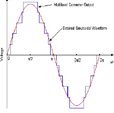
Fig.2 Desired Sinusoidal Waveform and Multi Level Inverter Output
The Harmonic Elimination Theory is based upon identifying the proper switching angles such that they eliminate desired harmonics from the fourier function of the output voltage waveform. For achieving a wide modulation index with minimum THD for the output waveforms, a generalized SHE method is proposed. The method is called Virtual Stage PWM. Out of the total degrees available in a multi level inverter, one degree is used to control the magnitude of the inverter voltage and rest are used to eliminate the harmonics in SHE method. The Selective harmonic elimination is done using solving the transcendal equations for the unknown angle values. The equations given below shows a set of transcendal equations for 4 variables.
IV.SIMULATION CIRCUITS AND RESULTS
ISSN (Print) : 2320 – 3765 ISSN (Online): 2278 – 8875
I
nternational
J
ournal of
A
dvanced
R
esearch in
E
lectrical,
E
lectronics and
I
nstrumentation
E
ngineering
(An ISO 3297: 2007 Certified Organization)
Vol. 5, Issue 5, May 2016
Fig.3 Simulation Circuit with Resistive Load
Fig.4 Simulation Circuit with Induction Motor Load
ISSN (Print) : 2320 – 3765 ISSN (Online): 2278 – 8875
I
nternational
J
ournal of
A
dvanced
R
esearch in
E
lectrical,
E
lectronics and
I
nstrumentation
E
ngineering
(An ISO 3297: 2007 Certified Organization)
Vol. 5, Issue 5, May 2016
The output voltage waveforms with Resistive load and their corresponding FFT Spectrum are given in figures 5 and 6 respectively.
Fig.5 Output Voltage Waveform with Resistive Load
Fig.6 FFT Spectrum of the Output voltage Waveform with Resistive Load
The output voltage waveforms with Induction Motor load and their corresponding FFT Spectrum are given in figures 7 and 8 respectively. It can be seen that there is no much increase in the THD even with an induction motor load. The spikes happening in each transition level of voltage is also negligible for this kind of load. The input Voltage to the stator of the Induction Motor can be considered as almost sinusoidal.
ISSN (Print) : 2320 – 3765 ISSN (Online): 2278 – 8875
I
nternational
J
ournal of
A
dvanced
R
esearch in
E
lectrical,
E
lectronics and
I
nstrumentation
E
ngineering
(An ISO 3297: 2007 Certified Organization)
Vol. 5, Issue 5, May 2016
Fig.8FFT Spectrum of the Output voltage Waveform with Induction Motor Load
The motor performance was found to be satisfactory after running a 0.25 HP single phase induction motor with a constant load torque of 5 Nm. The motor speed is acquiring a constant speed of 140 rad/s with a tolerance range of 3 rad/s within 0.35 seconds after switching on. The parameters of the motor was selected on the basis of a typical 0.25 HP single phase induction motor. The inrush current was found to be under the tolerance limits.
Fig.9 Speed of the Induction Motor
ISSN (Print) : 2320 – 3765 ISSN (Online): 2278 – 8875
I
nternational
J
ournal of
A
dvanced
R
esearch in
E
lectrical,
E
lectronics and
I
nstrumentation
E
ngineering
(An ISO 3297: 2007 Certified Organization)
Vol. 5, Issue 5, May 2016
Fig.10 Stator Input current to the Induction Motor
V.CONCLUSION
A new hybrid single phase 27 level multi level inverter which feeds a single phase induction motor was proposed. The motor performance with this multi level inverter was found to be satisfactory even without the use of a filter. The proposed topology consists of 3 cascaded H Bridges and the stresses on the switches were found to be considerably less when compared to other topologies.The switching and controlling technique used was simple and efficient which gives less THD and maximum efficency with less circuit complexity. The hardware of the circuit can be easily achieved and a Microcontroller level intelligence can easily serve the purpose for implementing the switching technique.
REFERENCES
[1] Y.S.Lai andet al. “Topology for Hybrid Multi Level Inverter”, IEEProc-Electr.Power Appl., Vol. 149,November 6 Nov2002
[2] K Ramani and A Krishnan. “New Hybrid 27 Level Multilevel Inverter fed Induction Motor Drive”, International Journal of Recent Trends in Engineering, Vol. 2, No. 5, November 2009
[3] Kiruthika P and Ramani K. “Design of Hybrid Multi-Level Inverter with Minimum Number of Switches Interface with Photo Voltaic”, IEEE Sponsored 2nd International Conference On Electronics And Communication System, ICECS 2015
[4] S. Mariethoz and A.C. Rufer. “Design and control of asymmetrical multilevel inverters”IECON’02, November 2002.
[5] M. Veenstra and A. Rufer. “Control of a hybrid asymmetric multilevel inverter for competitive medium voltage industrial drives”. IAS’2003, 1:190 – 197, October 2003.
[6] P.K. Steimer and M.D.Manjrekar. “Practical medium voltage inverter topologies for high power applications”. IAS’2001 ConferenceProceedings, 3:1723–1730, September 2001