Vol. 6, Issue 10, October 2017
Virtual Prototyping, Simulation and Control
of a 2-DOF Quadrotor Using Tracking
Control System
W. Malaquias1, M.F.Mollon2, E.H.Kaneko3, W. S. Chaves4, L. Niro5, M.A.F.Montezuma6
Master in Mechanical Engineering, Federal University of Technology – Paraná, Cornélio Procópio, Paraná, Brazil1
Graduated Student, Federal University of Technology – Paraná, Cornélio Procópio, Paraná, Brazil2,3,4
Substitute Professor, Federal University of Technology – Paraná, Cornélio Procópio, Paraná, Brazil5
Professor, Federal University of Technology – Paraná, Cornélio Procópio, Paraná, Brazil6
ABSTRACT:In this project is presented the development of a didactic plant for a quadrotor consisting of four rotors arranged in cross shape. The dynamics of the system is non-linear and multivariate with two degrees of freedom (2-DOF) related to the Roll and Pitch movements. In addition, the identification of the structure parameters isperformed through 3D modeling in SolidWorks software, and these parameters areemployed in the generation of the mathematical modeling of the system, which isdone through virtual prototyping with the dynamic analysis software MSC ADAMS, resulting in a linear and a non-linear models that areused to apply the tracking control system with state feedback and entire eigenstructureassignment. The linear model isemployed to generate the gains applied in the controller and the non-linear model to represent the real plant dynamics. The models are simulated by the Matlab/Simulink software in co-simulation with the MSC ADAMS, in order to verify if the gains obtained by the linear model are sufficient to control the system represented by the non-linear model. Therefore, the control performed for a step and sinusoidal inputsignals, whose controlled variables are the Roll and Pitch angles, presented satisfactory results.
KEYWORDS:Quadrotor, Tracking System, Multivariable Control,Virtual Prototyping.
I. INTRODUCTION
The Unmanned aerial vehicles (UAVs) are aircrafts that can operate autonomously without a pilot or remotely by an operator [1]. This type of equipment is used in several areas of applications such as agriculture, maintenance of data transmission lines, rescue operations, environmental monitoring, as well as military mapping tasks and exploration of unknown or hazardous areas [ 1, 2, 3, 4, 5]. The quadrotor or drone is a type of UAV that has the ability to plan, take off and land vertically, besides its advantages of low maintenance cost and simplicity in its construction due to the system being composed of a structure with four rotors fixed on symmetrically distributed rods [4, 5, 6]. However, the drone is considered a dynamically unstable non-linear system that requires an appropriate control system, being its stabilization a Multiple Input Multiple Output (MIMO) problem that is subject to uncertain parameters and external disturbances [7]. The control of the aircraft is done by varying the relative speed of the four rotors, thus producing the necessary torques to perform the movements [1, 7]. In addition, the system model is obtained by the multibody modeling technique that allows determining the dynamics of the system through mathematical equations [8]. Nevertheless, obtaining mathematical expressions can be an arduous and error-prone work, being compensated by the use of dynamic analysis software such as ADAMS, responsible for generating these expressions automatically and streamlining the modeling process [8].
Vol. 6, Issue 10, October 2017
presentations of modern subjects in courses and disciplines focused on control systems [9]. Based on this context, the objective of this project is developing a didactic simulator that represents the dynamics of a 2-DOF quadrotor, as well as the construction of the didactic plant, identification of its components through SolidWorks software, obtaining the virtual prototyping model via ADAMS software and development of a tracking control system with eigenstructure assignment for the roll and pitch movements. In addition, the control system is built and simulated in Matlab/Simulink with satisfactory results.
II. RELATED WORKS
The related works is focused on the development of quadrotor systems by observing the characteristics of the projects, such as modeling strategies and aircraft attitude control.
In [7] a robust MIMO control system based on the H∞norm is presented. The non-linear system is composed of a 2-DOF quadrotor coupled to a steel table. The studies are concentrated on the control of the roll and pitch movements and also on the behavior of the H∞ controller when it is subjected to external disturbances. The developed controller presented optimum performance with the ability to reject noise, external disturbances and suppressing uncertainties of the mathematical modelling. This work is similar to the one presented in [10], but the modeling performed for the quadrotor is done through the ADAMS software, responsible for generating the system state space model.
Differently from [7] and [10], the work developed by [11] presents a quadrotor with 4 degrees of freedom, contemplating the angular movement of Roll, Pitch and Yaw angles, including a limited displacement in the Z axis (altitude). In this project, a dSpace DS1103 acquisition board and an inertial sensor with 6-DOF are used to provide parameters in real time, so that the control algorithm optimized navigation solutions. The dynamic model of the system is obtained using the Lagrange method and a Proportional Derivative (PD) control algorithm is elaborated for the aircraft attitudes in the experimental tests.
In the project of [12] a PD controller is used to stabilize the altitude and the attitudes of the aircraft as in [11], but this work presents a new type of quadrotor, in which the rods fixed to the rotors vary in length by means of step motors in its interior, being responsible for increasing or decreasing the size of the rods according to the movement of the quadrotor. The modeling of the system was performed by Newton-Euler method and the simulations done in Matlab were efficient, since the control followed the desired inputs.
In [13] a methodology is used to identify the parameters of the quadrotor using the SolidWorks software to obtain geometrical data, such as center of mass and inertia moments of the parts that compose the aircraft. An inertial unit of measurement is used to estimate the attitudes of the quadrotor, which is necessary for a controller based on the linearization method with feedback.
The differential of this project is in the modeling of the 2-DOF quadrotor through the SolidWorks and ADAMS/View softwares that together turn easy the obtaining of the dynamic model of the system and allow changes in the same in a fast and practical way, besides the working with the non-linear model generated by ADAMS in the simulations to express some nonlinearities that approximate to the real quadrotor system.
III.DEVELOPED DIDACTIC PLANT
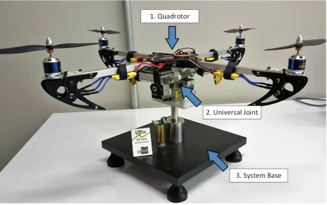
The didactic plant of this work is developed in three parts. The first part of quadrotor is assembled using the HobbyKing CSL-X525 chassis with 600 mm wingspan and a structure composed of four aluminum rods and other parts in carbon fiber, providing mechanical resistance and weight reduction. The total weight of the quadrotor is 1,297.33 grams considering the following components coupled to the structure:
Four 11.1V BL2215 / 20 Prop 9 "- 10" Outrunner Brushless motor with 8"x4.5" propellers;
Vol. 6, Issue 10, October 2017 Two 11.1V and 35C Transmetic 2200mAh batteries;
Four Electronic Speed Control (ESCs) model ESC-25A with operating range from 5.6 to 17V;
Screws, washers and nuts to fix the structure and components.
The second part of the development consists in the construction of a instrumented universal joint that allows the system two degrees of freedom, being coupled to it two encoders in order to measure the angular displacement of roll and pitchmovements. In general, the joint was made of lightweight materials giving a total weight of 733.45 grams, including the weight of the encoders. The last part developed is the basis for the didactic plant, which is used for joining and supporting the other parts of the structure, being composed of carbon steel and stainless steel, weighing approximately 12,935.17 grams. This high-weight material is used in the base to ensure that the quadrotor does not flight when it is in operation and does not present linear displacement in relation to the reference axes. Figure 1show the complete quadrotor plant developed in this project, highlighting each of the developmental parts. The system has a total weight of 14,453.29 grams and its main application is in control of 2-DOF quadrotor attitude, allowing the development of controllers that act on the roll and pitch angles of the aircraft.
To analyze the dynamics of a quadrotor it is necessary to define a coordinate system in the center of its chassis. The X and Y axes are thus located on the rods of the aircraft, as can be seen in Figure 2. At the ends of the rod coincident with the X axis are located the rotors 1 and 3, which have propellers with the same angle of incidence and are rotated clockwise. On the other hand, in the rod coincident with the Y axis there are the rotors 2 and 4 which have propellers with inverse angle of incidence to rotors 1 and 3 and are rotated in the counterclockwise way. This setting is necessary to cancel the reactive torques produced by the rotors and prevent unwanted yaw movement from occurring.
Figure 1 – Quadrotor didactic plant.
Vol. 6, Issue 10, October 2017
3, and for the rotors 2 and 4 the speed is the same. In this scenario, an angular momentum is produced around the Y axis representing the positive or negative pitch movement of the system, as shown in items c and d of Figure 2.
Figure 2 – Angular movements of the quadrotor.
IV. DYNAMIC SYSTEM MODELING
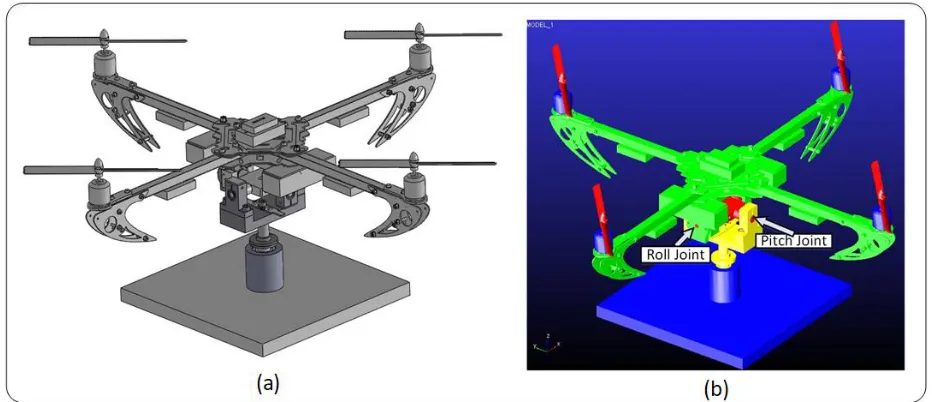
The experimental dynamic model isdeveloped in conjunction with SKA's SolidWorks software and MSC's ADAMS/View software. The first one is used to create the 3D model of the quadrotor and its components. The main advantage of SolidWorks is the physical data insertion of each piece that composes the didactic plant, through which the software provides information about the center of mass and moment of inertia for these parts, for example. Therefore, to create the model it is necessary to carry out the weighing, sizing, modeling and obtaining the volume and specific mass for each component present in the project. In addition, the model construction followed the same conditions imposed for experimental plant, being the result similar to the real model presented in Section III. Figure 3a illustrates the model assembled in SolidWorks.
Figure 3 – Quadrotor model. (a) Solidworks; (b) ADAMS.
Vol. 6, Issue 10, October 2017
software, being divided into the following parts: base, base axis, instrumented universal joint and quadrotor, which are represented by the colors blue, yellow, red and green, respectively. With the exported model, the physical properties of its elements, such as weight, moments of inertia and center of mass were inserted, being all the coordinates measured in relation to the reference system previously defined. In addition, four joints are used in the modeling, two fixed and two of revolute. The first one is created between the "ground" and the base in order to hold the system in the space, since there are no movements of translation in the axes. The second fixed joint is created between the base and the base axis to avoid Yaw movement. The third is a revolute joint located between the base axis and the instrumented universal joint, defining the pitch degree of freedom shown in Figure 3b. The fourth joint is inserted between the quadrotor and the instrumented universal joint, creating the roll degree of freedom, also illustrated in Figure 3b.
The movement around the two degrees of freedom is limited in the modeling in order to adapt the model to the real system. Then, the angular movement of the Roll and Pitch are delimited by the interval of -23º to 23º that is the minimum and maximum movements allowed by the didactic plant. To represent the dynamics of the rotors, four thrust forces are inserted, and their values are stored in variables. In this way, the input and output variables that is used to generate the model are shown in Table 1.
Inputs Outputs
Thrust Rotor 1 Roll Angle Thrust Rotor 2 Pitch Angle
Thrust Rotor 3 Roll Angular Speed ̇ Thrust Rotor 4 Pitch Angular Speed ̇
Table 1 – Inputs and outputs of the quadrotor dynamics model.
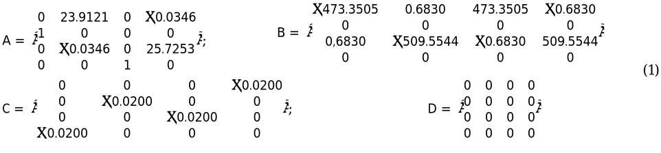
Based on the inputs and outputs seen in Table 1, the ADAMS software provided the linear and non-linear dynamic models. The first one is made by linearizing the system of non-linear equations around an operating point, resulting in a set of linear equations invariant in time in the form of state space. Thus, linearizing around the equilibrium condition yields the matrices of Equation (1).
A =
0 23.9121 0 −0.0346
1 0 0 0
0 −0.0346 0 25.7253
0 0 1 0
; B =
−473.3505 0.6830 473.3505 −0.6830
0 0 0 0
0,6830 −509.5544 −0.6830 509.5544
0 0 0 0
(1)
C =
0 0 0 −0.0200
0 −0.0200 0 0
0 0 −0.0200 0
−0.0200 0 0 0
; D =
0 0 0 0 0 0 0 0 0 0 0 0 0 0 0 0
V.THRUST CURVES OF THE ROTORS
In this section we describe the experimental procedure to obtain the rotors thrust curves, which is used for simulation and enable the experimental implementation of the system in future works. The thrust forces generated by the rotation speed of the motors and their propellers are directly related to the variation of the Pulse-Width Modulation (PWM) signal supplied to them. In order to define mathematically the relationship between thrust and PWM, an alternating thrust assay is carried out, which is conducted experimentally using a load cell model S10 from Alfa Instruments with a capacity of 10 kg and sensitivity of 2 mV/V with tolerance of ± 10%.
Vol. 6, Issue 10, October 2017
from National Instruments, are used to acquire these values in volts. However, for carrying out the thrust assays it is necessary to convert these values to Newtons with the LabVIEW. As an experimental procedure, the alternating test is performed four times for each rotor, in which the PWM value is raised from 0% to 100% and reduced to 0% again, in increments of 10 in 10% in intervals of 10 seconds. The average obtained among the four tests is used to get the thrust curve of each rotor, which is fitted based on a least squares method through a polynomial regression that also provides a mathematical relationship between the applied PWM and the resulting thrust.
VI. TRACKING CONTROL SYSTEM AND MATLAB/SIMULINK SIMULATION
The characteristics of a linear system are related to its eigenvalues and eigenvectors, which are used to characterize the location of the poles and zeros in the temporal response of the system [14]. The eigenvalues are responsible for the stability and growth or decay rate of the temporal system response, while the eigenvectors are related to the shape of this response [15]. In this way, the choice of eigenvalues and eigenvectors for the system characterization is called the auto-structure assignment, being used in this project to build the quadrotor control system, which is presented by [16] as a control by entire eigenstructure assignment, in other words, the controller is based on the attribution of eigenvectors and eigenvalues in a system in the state space configuration applied to multiple inputs and outputs (MIMO). The linearized open-loop system is represented below by the nth-order state equations and the pth-order
output equations.
̇ = + (2)
= = (3)
where A is the state matrix, B is the input matrix, C is the output matrix, y is a vector p x 1 and w = Ex is a vector m x 1
representing the outputs that are required to follow an input vector r. The objective of the state feedback control is that the vector w follows the input command r in the steady response, being this input a constant signal by parts. According to [16], the method consists in adding a comparator and integrator vector that satisfies Equation (4) and the control law to be used is described in Equations (5) and (6).
̇ = − = − (4)
= = + = [ ] (5)
= [ ] (6)
Figure 4 illustrates the diagram representing the feedback control system of the quadrotor, based on the equations of state and output given by Equations (2) and (3), respectively, and also by the control law present in Equation (5). This law can be used to assign the closed-loop eigenvalue spectrum, if and only if, the extended plant and the control matrices ( , )are controllable [16]. Equation (7) illustrates the complete representation for the closed-loop application.
′̇= ̇
̇ =
+
− + = ′ + ′ (7)
The feedback matrix must contain the eigenvalues of the root of the closed-loop plant which are all in the left complex half-plane, and the matrix is obtained by selecting the eigenvalues (λ) and eigenvectors (v) to be assigned to the matrix of the closed-loop plant ′ .
Vol. 6, Issue 10, October 2017
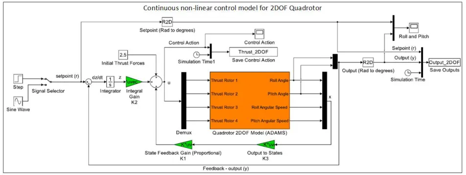
used to system control around the linearization position of a null roll and pitch angles. This model is represented by the four matrices in Equation (1). Figure 4 shows the block diagram for the linear model of the quadrotor, being the values of the roll and pitch angles in radians the controlled variables of the system and which must follow the reference values defined by a step or sinusoidal signal type with its inputs converted from degrees to radians.
Figure 4 – Blocks diagram of the 2-DOF quadrotor linear model.
The non-linear model is used to simulate the performance of the real control plant and to verify the effectiveness of the developed control system. In general, this simulation aims to verify if the control obtained from the linearized model is efficient and adequate to stabilize the non-linear model around the point of linearization, in other words, if the gains obtained in Equation (6) in the linear model are sufficient to control the non-linear quadrotor model. Figure 5 illustrates the model that is used in Section VII for system analysis.
Vol. 6, Issue 10, October 2017 VII. RESULTS AND DISCUSSION
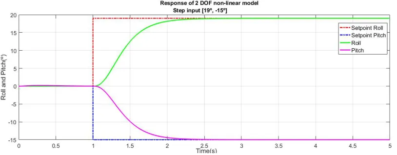
In order to evaluate the tracking control system developed in Section VI, two test scenarios based on step and sinusoidalinputsignalsare defined. In this context, the controlled variables of the system are the roll and pitch angles that are set at 19º and -15º, respectively. Table 2 shows the characteristics of the input signals used in the assay.
Step Signal Sinusoidal Signal
( ) = = 19°;0, =−015°≤, < 1 ≥1 ( ) = = 19° sin( ) ; = −15° sin( ) , ≥0
= 1 /
Table 2 – Step and sinusoidal input signals used in the test scenarios.
The simulations of the control plant for the input signals in Table 2 are performed for the non-linear model constructed by ADAMS software. In this way, the linear model of the quadrotor is used to calculate the feedback of states (K1) and integral (K2) gains based on the set of eigenvalues present in Equation (8). This configuration is used to stabilize the system within two seconds and with the control actions compatible with the thrust assays performed in Section V.
( + ) = {−6.9,−6.9,−6.8,−6.8,−6.5,−6.5} (8)
For the characteristics analysis of the 2-DOF quadrotor plant, the charts with the thrust forces applied to each rotor and the angular roll and pitch displacements converted from radians to degrees are used. Figure 6 shows the system responses for a step input signal, being red and blue dotted lines the reference value for the roll and pitch angles, respectively, as well as continuous green and pink lines representing the responses obtained for these angles based on the control of the non-linear model.
Vol. 6, Issue 10, October 2017
Figure 7 – Control action for step input signal.
Based on Figure 6, it is possible to verify that the quadrotor model satisfactorily follows the step input signal, stabilizing it in an approximate time of two seconds. In addition, for the control action of each rotor, there is no controller saturation for the set of eigenvalues employed, with the maximum and minimum applied thrust values of 3.3N and 1.9N, representing on average 59.78% and 41.35% of the PWM supplied to the rotors, respectively as shown in Figure 7. In addition, in Figure 6 there are small swings in the roll and pitch angles responses in the period of 0 to 1 second, since the didactic plant is not fully symmetrical. However, these oscillations are compensated by the controller as shown in Figure 7.
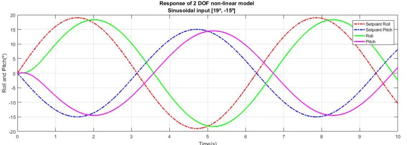
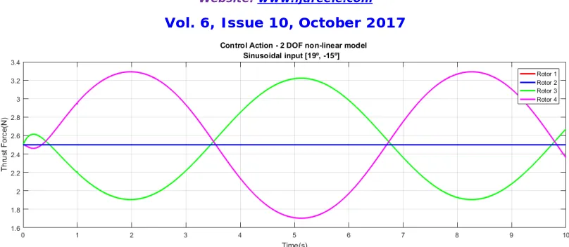
The second simulation is performed for a Sinusoidal signal input with its characteristics presented in Table 2. Figure 8 shows the system responses in comparison with the reference values defined for the roll and pitch angles. In general, the control of the system is performed satisfactorily, since its outputs followed the setpoint values defined by the sinusoidal wave, as well as the desired angular frequency ( ) of 1 rad/s or the period of approximately 6.29 seconds is applied. However, it is possible to observe a delay of 0.45 seconds between the references and the system outputs, presenting an error of 0.7 degrees for the roll angle and 0.5 degrees for the pitch angle. It happens because the reference signal is not continuous in parts, which promotes a delay in the controller responses. For the control action of each rotor, it can be said that there is no controller saturation, since the maximum and minimum values applied are 3.3N and 1.7N, corresponding approximately 59.78% and 38.35% of the applied PWM signal, respectively. Figure 9 illustrates the control action for the rotors.
Vol. 6, Issue 10, October 2017
Figure 9 – Control action for sinusoidal input signal.
VII. CONCLUSION
This project presented the development of a didactic plant for a 2-DOF quadrotor, being possible to simulate its behavior on the influence of a tracking control system with state feedback on the aircraft's rolling and pitching movements. The modeling developed with the MSC ADAMS software, coupled with the 3D model of the system built in SolidWorks, proved to be advantageous, since it was possible to quickly obtain the dynamic model of the quadrotor, besides the facility to change the dynamics of the system when compared to the traditional mathematical modeling. In addition, the linear model generated by ADAMS was used to calculate the controller gains and the non-linear model represented the real plant dynamics. The simulations were carried out in the Matlab/Simulink environment linked to the ADAMS Software, which were investigated whether the gains calculated by the linear model were sufficient to control the non-linear model of the plant. For this, a step and sinusoidal signals were used as reference for controlling the attitude of the aircraft, and the results were satisfactory, due to the stabilization time in the reference valueswithin the limit of 2 secondsand the application of the control action compatible with the thrust assays performed.
Finally, as future work, we intend to control the real system of the quadrotor in order to confront the responses obtained by the simulation, besides the modeling and control for the system in 3-DOF, including the yaw movement. Another possibility would be the implementation of other control techniques, such as the robust based on H∞ norm for system control in 2 and 3-DOF, and confront it with the tracking control system with state feedback and complete eigenstructure assignment developed in this work.
REFERENCES
[1] T. T. Nwe, T. Htike, K. M. Mon, Z. M. Naing, Y. M. Myint. "Application of an Inertial Navigation System to the Quad-rotor UAV using MEMS Sensors". Engineering and Technology, v. 42, 2008, pp. 578-582.
[2] H. Eisenbeiss. "A mini unmanned aerial vehicle (UAV): system overview and image acquisition". International Archives of Photogrammetry. Remote Sensing and Spatial Information Sciences, v. 36, n. 5/W1, 2004, pp. 1-7.
[3] A. M. Samad, N. Kamarulzaman, M. A. Hamdani, T. A. Mastor, K. A. Hashim, "The potential of Unmanned Aerial Vehicle (UAV) for civilian and mapping application," 2013 IEEE 3rd International Conference on System Engineering and Technology, Shah Alam, 2013. [4] S. Bouabdallah, M. Becker, R. Siegwart, "Autonomous miniature flying robots: coming soon! - Research, Development, and Results," in IEEE
Robotics & Automation Magazine, v. 14, n. 3, 2007, pp. 88-98.
[5] F. Kong, S. Chen, X. Wang, "Development of a practical experimental platform for control system of the quadrotor," The 27th Chinese Control and Decision Conference (2015 CCDC), Qingdao, 2015, pp. 2503-2508.
[6] M. F. A. Rahman, A. I. C. Ani, S. Z. Yahaya, Z. Hussain, R. Boudville ,A. Ahmad, "Implementation of quadcopter as a teaching tool to enhance engineering courses," 2016 IEEE 8th International Conference on Engineering Education (ICEED), Kuala Lumpur, 2016, pp. 32-37. [7] R. C. Sampaio, M. Becker, A. A. G. Siqueira, R. Breganon, F. Salvi, E. M. Belo."Model-Based Optimal H∞ Controller on the Stability of a
2-DoF Quadrotor". In: ASME 2011 International Design Engineering Technical Conferences and Computers and Information in Engineering Conference. American Society of Mechanical Engineers, 2011, pp. 955-962.
[8] A. S. Ioriatti."Dynamic study of a top loader washing machine using multibody system". Master Thesis - Engineering School of São Carlos, University of Sao Paulo, São Carlos, 2007, pp. 114.
Vol. 6, Issue 10, October 2017
[10] R. Breganon, R. C. B. Sampaio, M. M. Souza, F. T. B. Salvi, E. M. Belo, M. Becker. "Hardware-In-The-Loop Simulation Of An H-Infinity Controller On The Stabilization Of A 2-Dof Quadrotor". In: DINAME 2011 - 14th International Symposium on Dynamics Problems of Mechanics, São Sebastião, 2011.
[11] M. K. Bayrakceken, M. K. Yalcin, A. Arisoy, A. Karamancioglu, "HIL simulation setup for attitude control of a quadrotor," 2011 IEEE International Conference on Mechatronics, Istanbul, 2011, pp. 354-357.
[12] N. Y. Kamil, D. Hazry, K. Wan, Z. M. Razlan. "Trajectory tracking based on arm's length variation". Journal of Theoretical and Applied Information Technology, v. 79, n. 3, 2015, pp. 528.
[13] M. Elsamanty, A. Khalifa, M. Fanni, A. Ramadan, A. Abo-Ismail, "Methodology for identifying quadrotor parameters, attitude estimation and control," 2013 IEEE/ASME International Conference on Advanced Intelligent Mechatronics, Wollongong, NSW, 2013, pp. 1343-1348. [14] H. Kim, Y. Kim, "Partial eigenstructure assignment algorithm in flight control system design," in IEEE Transactions on Aerospace and
Electronic Systems, v. 35, n. 4, 1999, pp. 1403-1409.
[15] P. H. M. Rêgo. "Convergence analysis of a hierarchical genetic algorithm for loop recovery through LQC/LTR controllers". Master Thesis – Post-Graduation Program in Electrical Engineering, Federal University of Maranhão, São Luís, 2007, pp. 147.