Electric Bicycle with Three Way Charging
Beenu Mary Panicker1, Abil P Sajeev2, Akhil P3, Akhl R Babu4, Arjun K U5, Nibin Varghese6
Assistant Professor, Dept of EEE, College of Engineering, Pathanapuram, Kerala, India1 B. Tech Student, Dept of EEE, College of Engineering, Pathanapuram, Kerala, India2 3 4 5 6
ABSTRACT: The pollution due to automobiles is increasing day by day hence the pollution level at cities and urban areas are at dangerous levels due to use of automobiles. The use of electric vehicles for short distance travelling will help to reduce the pollution to some extent. The electric bicycle takes more time for recharging the battery this is not feasible one this is the main disadvantage of existing electric bicycle. In this project our attempt is to eliminate or reducing dependency on recharging from main supply by introducing a self recharging mechanism. Here we introducing an electric bicycle having three way charging mechanism. This electric bicycle uses dc generator for generating power while running, uses solar panel when bicycle is at rest and a charger that operates from main power supply for charging the battery. This electric bicycle uses 24V 250W brushless direct current (BLDC) hub motor and Lithium ion (Li-ion) battery. The use of BLDC hub motor in the bicycle that avoids the complexity and losses while using the permanent magnet direct current (PMDC) motor. The Li-ion battery replaces the sealed maintenance free (SMF) battery which is used in existing electric bicycles. Li -ion batteries are having more advantages as compared to SMF batteries.
KEYWORDS: brushless direct current motor, permanent magnet direct current motor, sealed maintenance free battery, Lithium ion battery
I. INTRODUCTION
II. BLOCK DIAGRAM
Block diagram of Electric bicycle
A. MOTOR
The hub motor is a conventional dc motor. The rotor is outside the stator with the permanent magnets mounted on inside. The stator is mounted and fixed onto the axle and the hub will be made to rotate by alternating currents supplied by using Electronic switching control by taking power from the batteries. Hub motor generates high torque at low speed. It is placed in the axle of bicycle which doesn’t need sprockets, brackets and drive chains to drive the wheel. The hub motor outer periphery is provided with holes for placing spokes hence BLDC hub motor can be easily mounted to the bicycle wheel. This means they are very reliable and have a long life. The main characteristic of Brushless DC Motor is that they may be controlled to give constant power at wide speed ranges. It operates at high efficiency.
Figure 1: BLDC hub motor
Specifications of hub motor
Power rating
250 W
Torque
12N-m
Speed (rpm)
300
Rated voltage
24V
Efficiency (%)
≥80
Table 1
Table 1 shows the technical specifications of the BLDC hub motor used in the bicycle. The technical specifications are sufficient for meeting the requirements for driving the bicycle.
B. LITHIUM-ION BATTERIES
Lithium-ion batteries are the most suitable in existing technology for electric vehicles because they can deliver high output because of having capability to store high power per unit of battery mass, allowing them to be lighter and smaller than other rechargeable batteries. These features also explain why lithium-ion batteries are already widely used for consumer electronics such as cell phones, laptop computers, digital cameras/video cameras, and portable audio/game players. Other advantages of lithium-ion batteries compared to lead acid and nickel metal hydride batteries include high-energy efficiency, no memory effects, no self discharging and a relatively long cycle life. The electric bicycle uses battery having capacity of 24V 15Ah capacity.
C. ELECTRONIC SPEED CONTROL (ESC)
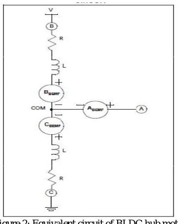
The electronic switching control is a switching circuitry which is used for running BLDC hub motor. Its main function is for providing supply for the windings of motor by sensing the rotor position. It is possible to determine when to commutate the adjacent stator coils by sensing the back EMF voltage from the non energized stator coil is due to passing of rotor permanent magnet of the BLDC hub motor. The obvious cost advantage of sensor less control is the elimination of the Hall position sensors. The BEMF, relative to the coil common connection point, generated by each of the motor coils,
Figure 2: Equivalent circuit of BLDC hub motor
R components are not shown in the A branch since no significant current flows in this part of the circuit so those components can be ignored.
D. DC – DC REGULATOR
It is essential to regulate the voltage output from the solar panel or Dc generator before it is supplied to the battery. This is used to regulate an input voltage to provide a constant output voltage. The output of the solar panel is not always be stable due to fluctuations in intensity of sunlight, angular changes with respect to the direction of sunlight, as well as other environmental factors. Also the output from the DC generator will show variation in the output voltage due to change in speed of bicycle hence the voltage Regulator/Boost Converter comes into Electric bicycle. A DC-DC boost converter is a power converter that will take in a DC voltage and gives a higher value DC voltage .The output of the solar panel or DC generator is the input of the boost converter, which then outputs into the battery for charging. Because the output of the solar panel or DC generator will be varying widely, we need a voltage regulator/boost converter that will take an input from a wide range of voltages and output a specific, constant voltage value. In this electric bicycle using LM2577 DC-DC boost converter. The output of DC-DC converter output is set to 29V for charging the battery.
E. DC GENERATOR
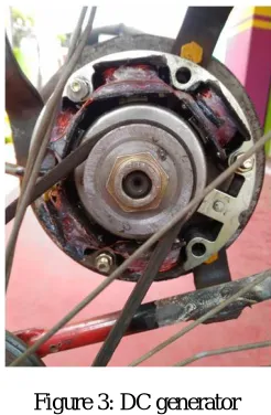
This electric bicycle uses a DC generator for generating electric power while running the bicycle. Here the Dc generator is connected to back wheel of the bicycle followed by belt driven mechanism with ratio of 1:3. When the bicycle is running, at this condition by help the of belt driven mechanism the DC generator generates the power. In dc generator using powerful permanent magnet as core and the stator is having 5 poles and each winding is connected in series. So it converts mechanical rotation into an electric current through Faradays law of induction. The stator conductor cuts the line of magnetic force, there by inducing current to pass through the wire. Due to this rotation is the mechanical energy is converted into electrical current in the coil. It is capable of generating 12V and 1A at 10 Km/hr speed.
Figure 3: DC generator
Figure 3 shows the DC generator used in the bicycle the generator is directly connected to the back wheel by using a belt. The DC Generator is fixed at the right side on the back wheel side of the bicycle by welding.
F. SOLAR PANEL
charging the battery is one of the methods of charging in the project. The charging by using the solar panel is done when the bicycle is at rest and when sunlight directly available.
G. BATTERY CONTROL AND PROTECTION
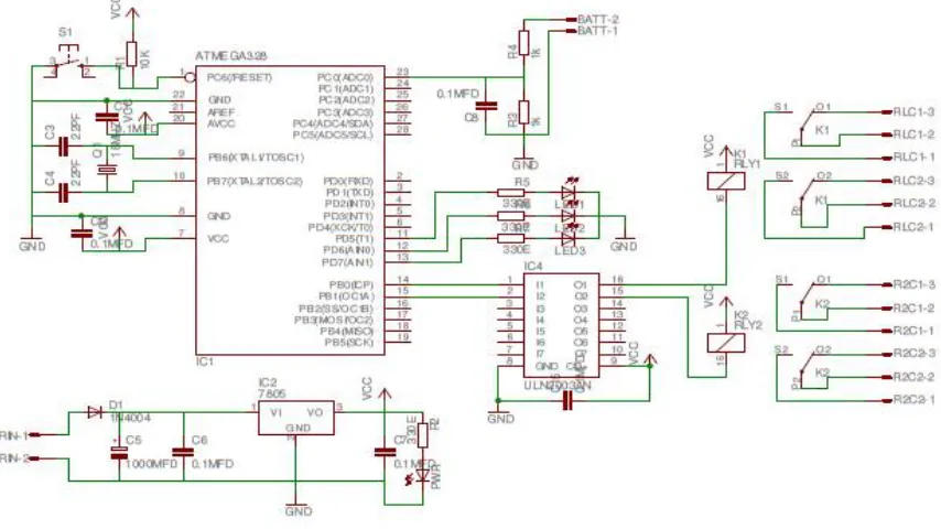
The battery control section is the core part of this project .The main function of battery control and protection section is to switching the battery to power source for charging or to switch battery supply to the motor. This section protects the battery from deep discharge and from over charging. In our project we include a battery level indicator for indicating the battery charge level. The battery level indicator consists of three LEDs which help for tracking the battery voltage level. The battery voltage level is monitored by the microcontroller with the help of analog inputs. Here we uses ATMEGA328 microcontroller for controlling and protection of the battery. The ATMEGA328 microcontroller is chosen because of its low power consumption. The switching of battery for charging or driving the motor is done by using an electromechanical relay .The relay is interfaced with microcontroller by using ULN 2003 IC. The driver IC is used to avoid complexity while using transistor as switch for operating relay. The microcontroller, relay and driver IC is powered with the help of voltage regulator 7805 by using battery as source.
Figure 4: Circuit diagram of Battery control and protection circuit
III. EXPERIMENTAL RESULTS
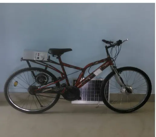
Figure 5: completed electric bicycle
IV. CONCLUSION
Self charging Electric bicycle is modification of existing electric bicycle. It is suitable for both city and country roads, that are made of cement, asphalt, or mud. This bicycle is cheaper, simpler in construction & can be widely used for short distance travelling especially by school children, college students, office goers, villagers, postmen etc. It is very much suitable for young, aged peoples. It can be operated free of cost. This bicycle is that it does not consume valuable fossil fuels thereby saving crores of foreign currencies. It is eco-friendly, economical & pollution free, as it does not have any emissions. Moreover it is noiseless and can be recharged with the AC adapter in case of emergency or cloudy weather. It can be driven by manual pedalling in case of any problem with the electric driving system.
REFERENCES
[1] Design and Implementation of Electric Assisted Bicycle with Self Recharging Mechanism International Journal of Innovative Research in Science, Engineering and Technology Volume 3, Special Issue 5, July 2014
[2] multidisciplinary journal of research in Engneering and technology An Improved & Efficient Electric Bicycle system with the Power of Real-time Information Sharing Chetan Mahadik,SumitMahindrakar,Prof. JayashreeDeka
[3] International Conference on Science, Technology, Engineering &Management An Innovative solar powered electric bicycle C.Sivapragash,C.Shankar, M.Nageena, B.Reetha Devi, K.Kiruthiga