Analysis and design of DVR performance
for voltage sag mitigation
T. Naveen Kumar
[email protected]
ABSTRACT:
This paper deals with terminology and various problems concerning ‘power quality issues’. Voltage sags and swells are the normal activities on the electric power network. These issues can be mitigated with voltage injection procedure utilising custom power device, Dynamic Voltage Restorer (DVR). In this paper we design a Dynamic Voltage Restorer (DVR) which is utilized for power quality growth. Here we advocate two control procedures that are the Proportional integral (PI) Controller and Fuzzy common sense (FL) Controller. Results of each the controllers are assessed to understand which the best power quality solution.
KEYWORDS-Dynamic Voltage Restorer, Pulse Width Modulation (PWM), PI with Fuzzy Logic Controller
I. INTRODUCTION
Voltage sags are now one of the mostimportant power quality problems in the powerdistribution systems. A voltage sag is a momentarydecrease in rms ac voltage (0.1-0.9 p.u. of thenominal voltage), at the power frequency, ofduration from cycles to a few seconds. Most voltagesags are caused by remote faults, such as singleline- to-ground fault, double line to to-ground faultand three phase fault on the power distributionsystem. [2]. Recently, power quality problems become a majorconcern of industries due to massive loss in terms oftime and money. Hence, there are always demandsfor good power quality, which positively resulting inreduction of power quality problems like voltagesag, harmonic, flicker, interruptions
and harmonicdistortion. Preventing such
phenomena isparticularly important because of the increasingheavy automation in almost all the industrialprocesses. High quality in the power supply isneeded, since failures due to such disturbancesusually have a high impact on production costs.
There are number of methods to overcome voltagesags. One approach is to use Dynamic VoltageRestorers with energy storage. The DVR is a powerelectronics device that is able to
compensate voltagesags on critical loads
dynamically. By injecting anappropriate voltage, the DVR restores a voltagewaveform and ensures constant load voltage. TheDVR consists of
Voltage Source Converter (VSC),injection
transformers, passive filters and energystorage (lead acid battery). The Dynamic VoltageRestorer (DVR) with the lead acid battery is anattractive
way to provide excellent dynamic
voltagecompensation capability as well as beingeconomical when compared to shunt-connecteddevices. The DVR is a custom power device that isconnected in series with the distribution system. TheDVR employs MOSFETs to maintain the voltageapplied to the load by
injecting three-phase outputvoltages whose
trigger on the PWMinverter. The components of control system unit aredq0-transformation, Phase-lock-loop (PLL) and thePI with FL Controller. PI Controller is a feedbackcontroller which drives the plant to be controlledwith a weighted sum of the error (differencebetween output and and desired set-point) and theintegral of that value. [1].
A new fuzzy logic (FL) method has been applied tocustom power devices, especially for active powerfilters. The operation of DVR is similar to that ofactive power filters in that both compensators mustrespond very fast on the request from abruptlychanging reference signals. In the literature, FLcontrol of DVR based on dq synchronous referenceframe (SRF). In three-phase supply voltages aretransformed into d and q coordinates. The referencevalues for Vd and Vq are compared with thesetransformed values and then voltage errors areobtained. FL controllers evaluating 9 linguistic rulesprocess these errors. Resulting outputs are retransformed into three-phase domain and comparedwith a carrier signal to generate PWM invertersignals. [4]
This paper presents the modeling and simulation ofa PI with FLC-based DVR under voltage sagphenomena. In this case, the PI with fuzzy logiccontroller has been incorporated instead ofconventional other controller. The simulation toolis the MATLAB/Simulink Power System Blockset(PSB). The capability of DVR to mitigate thevoltage sag is demonstrated by MATLABsimulation. The addition of PI with fuzzy logiccontrol to gives added advantage of faster responseas compared to the conventional one. [5]
II. CONTROL TECHNIQUES FOR DVR
The fundamental roles of a controller in a DVR are to detect thevoltage sag occurrence in the
system; calculate the compensatingvoltage, to generate trigger pulses of PWM inverter and stoptriggering when the occurrence has passed. Using RMS value
calculation of the voltage to analyze the sags does not give a fast andaccurate result. In this study the dqo transformations or parkstransformations is
used in voltage calculation. The dqo
transformationis a transformation of coordinates from the three phase stationarycoordinate system to the dq rotating coordinate system.[6] This dqomethod gives the information of the depth (d) and phase shift (q) of
voltage sag with start and end time.
…… (1)
……..(2)
………. (3)
After conversion, the three-phase voltage Va, Vb and Vc becometwo constant voltages Vd and Vq and now, they are easily controlled.In this paper, two control techniques have been proposed which are
proportional integral (PI) controller and fuzzy logic (FL) controller.
A. Proportional-Integral Controller
PI Controller is a feedback controller which drives the plant tobe controlled with a weighted sum of the error and the integral ofthat value. The
proportional response can be adjusted
bymultiplying the error by constant KP, called proportional gain.[7]
The contribution from integral term is
togive an accumulated offset that have been corrected previously.
B. Fuzzy Logic Controller
Fuzzy logic (FL) controller is one of the most successfuloperations of fuzzy set theory, its major features are the use oflinguistic variables rather
than numerical variables.[8] Thiscontrol
technique relies on human capability to understand thesystems behavior and is based on quality control rules. Fuzzy
Logic provides a simple way to arrive at a
definite conclusion based upon vague,
ambiguous, imprecise, noisy, or missing
inputinformation.[1]
The general structure of an FLC is represented in Figure 2 andcomprises of four principal components:
Fig.2: Basic structure of FL controller
• A Fuzzyfication interface which converts input data intosuitable linguistic values.
• A Knowledge Base which consists of a data base with thenecessary linguistic definitions and control rule set.
• A Decision Making Logic which, simulating a humandecision process, infers the fuzzy control action from theknowledge of the control rules and the linguistic variabledefinitions and
• A Defuzzyfication interface which yields a nonfuzzycontrol action from an inferred fuzzy control action.
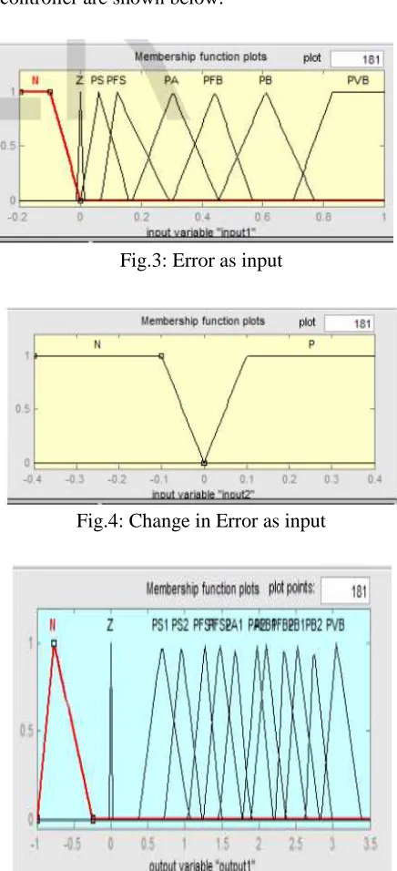
In this paper, two FL controller block are used for errorsignal-d and error signal-q. Error and Change in Error are theinputs to the fuzzy controller are shown below.
Fig.3: Error as input
Fig.4: Change in Error as input
In the decision-making process, there is rule base that linkingbetween input (error signal) and output signal. Table 1 show therule base used in this FL controller.
Table.1: Rule base
III. SIMULATION RESULTS
In order to understand the performance of the DVR along with control, a simple distribution network as shown in Fig.11 is implemented. There are different fault conditions like normal system, single line to ground fault, double line to ground fault, three phase fault and voltage sag simulated using MATLAB/SIMULINK software. PI with fuzzy logic controller is used for the control purpose. The DVR system connected to
the distribution system using a booster
transformer.
1) Double-line-to-ground fault with 50%
sagging
Fig.6Matlab model of DVR with double line to ground fault with 50% Sagging
Fig.7a. Injection voltage from DVR controlled by PI
Fig.7b. injection voltage controlled by FL
Fig.8b. Output voltage at load 1after injection voltage controlled by FL.
2) Balanced three-phase fault with 50% sagging
Fig.9 matlab model of DVR with balanced three-phase fault with 50% sagging
Fig.10a. Injection voltage from DVR controlled by PI
Fig.10b. injection voltage controlled by FL.
Fig.11a. Output voltage at load 1 after injection voltage from DVRcontrolled by PI
Fig.12. THD generated when PI controller is applied
Fig.13. THD generated when FL controller is applied.
IV. CONCLUSION
In this paper, the modeling and simulation of DVR controlled by PI with Fuzzy Logic Controller has been developed using Matlab/Simulink. For the controller, the simulation result shows that the DVR compensates the sag quickly (50μs) and provides excellent voltage regulation. DVR handles different fault condition like normal system, single line to ground fault, double line to ground fault, three phase fault, voltage sag, balanced and unbalanced fault without any difficulties and injects the appropriate voltage component to correct any fault situation occurred in the supply voltage to keep the load voltage balanced and constant at the nominal value.
REFERENCES
[1] R. H. Salimin and M. S. A. Rahim “SimulationAnalysis of DVR Performance for Voltage
SagMitigation” The 5th International
PowerEngineering and Optimization
Conference(PEOCO2011), Shah Alam,
Selangor,Malaysia: 6-7 June 2011, pp. 261-266. [2] Paisan Boonchiaml Promsak Apiratikull andNadarajah Mithulananthan2“Detailed Analysisof Load Voltage Compensation for DynamicVoltage Restorers” IEEE Transactions, 2006.
[3] Omar R and Rahim, N.A. “New ControlTechnique Applied in Dynamic VoltageRestorer for Voltage Sag Mitigation”Industrial Electronics and Applications, 2009.ICIEA 2009. 4th IEEE Conference, pp.848 --852.
[4] A. Teke K. Bayindir and M.Tu¨may“Fastsag/swell detection method for fuzzy logiccontrolled dynamic voltage restorer” IETGener. Transm. Distrib., 2010, Vol. 4, Iss. 1,pp. 1–12.
[5] B.Panda, A.K. Mahapatra and D.P. Bagarty*And S. Behera** “Fuzzy Logic Controller -Based Dynamic Voltage Restorer ForMitigation of Voltage Sag” InternationalJournal of Engineering Science andTechnology (IJEST), Vol. 3 No. 2 Feb 2011,pp. 996-1007..
[6] P. Boonchiam and N. Mithulananthan, “Understanding of DynamicVoltage Restorers through MATLAB Simulation,” Thammasat Int. J.Sc. Tech., Vol. 11, No. 3, July-Sept 2006.
[7] Nemati, M. Yousefian, H. A. Afshari, R. “Recognize The Role of A DVR in Power Systems” International Journal of Recent Trends in Engineering, Vol 2, No. 7, November 2009.
[8] Mattavelli, P. Rossetto, L. Spiazzi, G. Tenti, P. “General-Purpose Fuzzy Controller for DC-DC Converter” IEEE Transactions on Power Electronics, Vol. 12, No. 1, January 1997.
Author Profile: