Article
1
Multifunctional platform based on electroactive
2
polymers and silica nanoparticles for tissue
3
engineering applications
4
Sylvie Ribeiro1,2, Tânia Ribeiro3,4, Clarisse Ribeiro1,5,*, Daniela M. Correia6,7, João P. Sequeira
5
Farinha3,4, Andreia Castro Gomes2, Carlos Baleizão3,4 and Senentxu Lanceros-Méndez7,8
6
1 Centro/Departamento de Física, Universidade do Minho, 4710-057 Braga, Portugal.
7
2 Centre of Molecular and Environmental Biology (CBMA), Universidade do Minho, Campus de Gualtar, 4710-057
8
Braga, Portugal.
9
3 Centro de Química-Física Molecular and Institute of Nanosciences and Nanotechnology, Instituto Superior Técnico,
10
Universidade de Lisboa, 1049-001 Lisboa, Portugal.
11
4 Centro de Química Estrutural, Instituto Superior Técnico, Universidade de Lisboa, 1049-001 Lisboa, Portugal.
12
5 CEB - Centre of Biological Engineering, Universidade do Minho, Campus de Gualtar, 4710 057 Braga, Portugal.
13
6 Chemical Department and CQ-VR, Universidade de Trás-os-Montes e Alto Douro, 5001-801 Vila Real, Portugal.
14
7 BCMaterials, Basque Centre for Materials, Applications and Nanostructures, UPV/EHU Science Park, 48940 Leioa,
15
Spain.
16
8 IKERBASQUE, Basque Foundation for Science, 48013 Bilbao, Spain
17
18
* Correspondence: [email protected]; Tel.: +351-253406074
19
20
Abstract: Poly(vinylidene fluoride) nanocomposites processed with different morphologies, such
21
as porous and non-porous films and fibres, have been prepared with silica nanoparticles (SiNPs) of
22
varying diameter (17, 100, 160 and 300 nm) which in turn have encapsulated perylenediimide
23
(PDI), a fluorescent molecule. Structural, morphological, optical, thermal, and mechanical
24
properties of the nanocomposites, with SiNP filler concentration up to 16 wt% were evaluated.
25
Further, cytotoxicity and cell proliferation studies were performed. All SiNPs are negatively
26
charged independently of the pH and more stable from pH 5 upwards. The SiNPs introduction
27
within the polymer matrix increases the contact angle independently of the nanoparticle diameters
28
and the smallest ones (17 nm) improve the PVDF Young modulus from 0.94 ± 0.04 GPa for the
29
pristine polymer film to 1.05 ± 0.06 GPa. Varying filler diameter, physico-chemical, thermal and
30
mechanical properties of the polymer matrix were not significantly affected. Finally, the SiNPs
31
inclusion does not induce cytotoxicity in murine myoblasts (C2C12) after 72 h of contact and
32
proliferation studies reveal that the prepared composites represent a suitable platform for tissue
33
engineering applications, as they allow to combine the biocompatibility and piezoelectricity of the
34
polymer with the possible functionalization and drug encapsulation and release of the SiNP.
35
Keywords: Nano-structures; Polymer-matrix composites (PMCs); Mechanical properties; Thermal
36
properties
37
38
1. Introduction
39
The development of advanced multifunctional materials is essential for the development of
40
society [1]. Nanocomposites are among the most important materials for an increasing number of
41
applications due to the possibility of designing materials with tailored properties meeting specific
42
application demands in areas ranging from automotive [2-3] to food packaging [4-5] and tissue
43
engineering [6-7], among others. The introduction of inorganic nanomaterials into polymers allows
44
the combination of the rigidity and high thermal stability of the inorganic material with the
45
ductibility, flexibility and processability of the organic polymers [8], as well as the
46
introduction/tuning of further functionalities such as magnetic [9] or electrical properties [10].
47
Typical nanomaterials include nanoparticles, nanotubes, nanofibres, fullerenes and nanowires [11].
48
Among nanomaterials, silica is widely present in the environment and has several key features [12].
49
Properties of silica nanoparticles, such as high mechanical strength, permeability, thermal and
50
chemical stability, relatively low refractive index and high surface area, make these nanoparticles
51
highly interesting for applications [13]. Further, their biocompatibility and the different possibilities
52
to functionalize them are at basis of their large potential for biomedicine and tissue engineering
53
applications [14]. Silica nanostructures have been extensively used as supports or carriers in drug
54
delivery [15-16], nanomedicine [17-18] or bioanalysis [19]. Their characteristics can be tuned during
55
synthesis to obtain a wide range of particle diameters ranging from 20 to 500 nm, different pore sizes
56
and the incorporation of molecules such as drugs or fluorophores [19], as well as magnetic
57
nanostructures [20]. Mesoporous silica nanoparticles (MSNPs) [15, 21] have attracted particular
58
attention for their functionalization versatility. Silica-based mesoporous nanoparticles, due to the
59
strong Si-O bond compared to niosomes, liposomes and dendrimers, are more resistant to
60
degradation and mechanical stress, inhibiting the need of any external stabilization of the MSNPs
61
[22-23].
62
With respect to tissue engineering, different tissues require different microenvironments for
63
suitable regeneration [24]. Thus, muscle tissue has electromechanical response and needs electrical
64
stimulation to support ionic exchange, mainly sodium by calcium ion [25]. In this context,
65
electroactive polymers such as magnetoelectric [26-27], piezoelectric and conductive polymers [28],
66
among others [29], show strong potential for tissue engineering applications. Among the different
67
electroactive polymers, piezoelectric polymers have already shown their suitability for tissue
68
engineering [6, 24] due to their capacity to vary surface charge when a mechanical load is applied or
69
vice versa. These materials can play a significant role because the electric stimulation can be found in
70
many living tissues of human body, namely neural [30] and bone [31-32], and it can provide the
71
electromechanical solicitations for muscle [33]. Poly(vinylidene fluoride) (PVDF) is the
72
biocompatible piezoelectric polymer with the highest piezoelectric response and can be processed in
73
different morphologies, including fibres, spheres, membranes, and 3D scaffolds [24, 34] providing a
74
suitable platform for tissue engineering.
75
In order to further exploit the applicability of PVDF in regenerative medicine, polymer
76
nanocomposites based on PVDF using silica nanoparticles with different diameters were prepared,
77
improving the electroactive characteristics of PVDF with the aforementioned characteristics of
78
MSNPs for biomedical applications. Together with the physico-chemical characteristics of the
79
developed composites, their biocompatibility was evaluated in murine myoblast cells.
80
2. Materials and Methods
81
2.1. Materials
82
PVDF (Solef 1010) was purchased from Solvay, N,N-dimethylformamide (DMF) from Merck.
83
Absolute ethanol (EtOH, Panreac, 99.5%), ammonium hydroxide solution (NH4OH, 28% in water,
84
Fluka) and tetraethyl orthosilicate (TEOS, Aldrich, 99%) were used as received. Deionized water
85
from a Millipore system Milli-Q ≥ 18 MΩ cm was used in the synthesis of the silica nanoparticles.
86
Perylenediimide derivative (PDI) was synthesized according to the literature [35].
87
2.2. Silica nanoparticles
88
2.2.1. Preparation of the silica nanoparticles
89
Fluorescent silica nanoparticles, doped with PDI were prepared by a modified Stöber method
90
[36-37]. Water, absolute ethanol, and PDI (previously dispersed in ethanol, 1×10⁻⁶ M) were mixed
91
was kept under stirring at constant temperature for 24 h. After that time, the nanoparticles were
93
recovered and washed with ethanol (3 cycles of centrifugation). The nanoparticles were redispersed
94
in ethanol and dried at 50 ºC in a ventilated oven. The experimental details are provided in Table 1.
95
Table 1 - Experimental details used for the preparation of the SiNPs.
96
Particle diameter (nm)
EtOH (g)
H2O (g)
PDI solution (mL)
NH3 (mL)
TEOS (mL)
Reaction temperature (ºC)
17 84.13 7.99 3 1.51 4.46 50
100 105.73 4.65 4 6.68 9.00 30
160 53.18 11.03 4 2.67 4.46 50
300 53.18 11.03 4 2.67 4.46 30
97
2.2.2. Characterization of the SiNPs
98
Transmission electron microscopy: Transmission electron microscopy (TEM) images were
99
obtained on a Hitachi transmission electron microscope (model H-8100 with a LaB6 filament) with
100
an acceleration voltage of 200 kV. One drop of the dispersion of particles in ethanol was placed on a
101
carbon grid and dried in air before observation. The images were processed with the Fiji software.
102
Zeta potential: The surface charge of the nanoparticles was estimated with the use of zeta
103
potential (Zetasizer NANO ZS-ZEN3600, Malvern). The zeta potential of the fluorescent SiNPs with
104
different diameters were evaluated at different pH (3, 5, 7, 11, 13). To adjust the pH, it was used a
105
solutions of HCl (1M) and NaOH (1M). The average value and standard deviation for each sample
106
were obtained from 6 measurements.
107
108
2.3. Nanocomposite samples
109
2.3.1. Preparation of the SiNPs/PVDF nanocomposites
110
SiNPs/PVDF nanocomposites with 16 wt % of SiNPs were prepared by dispersing the
111
respective mass of SiNPs in the DMF solvent within an ultrasound bath for 4 h at room temperature.
112
The filler concentration was selected based in [38], as it shows a suitable filler content without
113
compromising the mechanical characteristics of the polymer matrix and allowing a suitable
114
dispersion of the filler. After obtain a good dispersion of the nanoparticles, PVDF was added with a
115
concentration of 15% (w/w) and the solution was magnetically stirred at room temperature until the
116
complete dissolution of the polymer. The materials were then prepared by different production
117
methods [34].
118
First, SiNPs/PVDF samples (porous and non-porous films) were prepared by solution casting
119
on a clean glass substrate and, in some cases, melted at different temperatures for different times
120
(table 2). The different preparation conditions allow to tailor both porosity and to study the
121
possibility of the nucleation of the electroactive β-phase of the polymer by the fillers [39]. The
122
thickness of the films ranges from 30 to 50 µm.
123
124
125
126
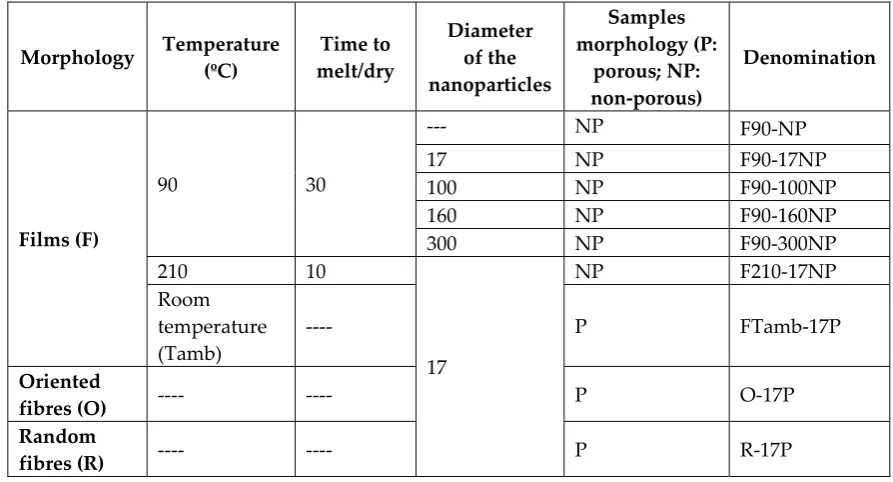
Table 2 - Denomination, relevant preparation conditions and morphology of the PVDF and
128
nanocomposite samples prepared in this work.
129
Morphology Temperature (ºC)
Time to melt/dry
Diameter of the nanoparticles
Samples morphology (P:
porous; NP: non-porous)
Denomination
Films (F)
90 30
--- NP F90-NP
17 NP F90-17NP 100 NP F90-100NP 160 NP F90-160NP 300 NP F90-300NP 210 10
17
NP F210-17NP Room
temperature (Tamb)
---- P FTamb-17P
Oriented
fibres (O) ---- ---- P O-17P
Random
fibres (R) ---- ---- P R-17P
130
For SiNPs/PVDF electrospun fiber mats, the solution was placed in a plastic syringe (10 mL)
131
fitted with a steel needle with inner diameter of 0.5 mm. After an optimization procedure,
132
electrospinning was conducted with a high voltage power supply from Glasman (model
133
PS/FC30P04) at 14 kV with a feed rate of 0.5 mL.h-1 (with a syringe pump from Syringepump). The
134
electrospun fibres were collected in an aluminum plate (placed at 20 cm from the needle) and in a
135
rotating drum (1500 rpm) to obtain random and oriented nanofibres, respectively.
136
Table 2 summarizes the main characteristics of the samples and the corresponding
137
denomination that refers the type of sample and processing temperature, the nanoparticle diameter
138
and the composite morphology. For example, F90-17NP is a film (F) obtained at 90 ºC (90) with
139
nanoparticles with a diameter of 17 nm (17), which is non-porous (NP).
140
141
2.3.2. Characterization of the nanocomposite samples
142
Scanning electron microscopy: A desktop scanning electron microscope (SEM) (Phenom ProX,
143
Netherlands) was used to observe the morphology and microstructure of the PVDF and
144
SiNPs/PVDF nanocomposites. This technique was also used to observe the cell morphology seeded
145
on the different fibrous samples. All the samples were added to the aluminium pin stubs with
146
electrically conductive carbon adhesive tape (PELCO TabsTM). The aluminium pin stub was then
147
placed on a phenom Charge Reduction sample Holder. All results were acquired using the ProSuite
148
Software. The images were obtained with an acceleration voltage of 10 kV. All results were acquired
149
using the ProSuite software.
150
Laser scanning confocal fluorescence microscopy: Laser scanning confocal fluorescence
151
microscopy (LSCFM) images were obtained with a Leica TCS SP5 laser scanning microscope (Leica
152
Mycrosystems CMS GmbH, Mannheim, Germany) using an inverted microscope (DMI6000), a HCX
153
PL APO CS 10x dry immersion objective (10x magnification and 0.4 numerical aperture) and a HC
154
PL FLUOTAR 50x dry immersion objective (50x magnification and 0.8 numerical aperture). Imaging
155
used the 488 nm line of an argon ion laser.
156
Contact angle measurements: Water contact angle (CA) measurements (sessile drop in dynamic
157
mode) were performed at room temperature in a Data Physics OCA20 set up using ultrapure water
158
the surface of the samples. Each sample was measured at six different locations and the mean contact
160
angle and standard deviation were calculated.
161
Fourier transform infrared spectroscopy: Fourier transform infrared spectroscopy (FTIR)
162
measurements in attenuated total reflectance (ATR) were performed at room temperature, using a
163
Nicolet Nexus 670 FTIR-spectrophotometer with Smart Orbit Accessory equipment. The analysis
164
was performed from 4000 to 600 cm-1, after 64 scans with a resolution of 4 cm-1. The spectra of each
165
sample was used to determine the relative content of the electroactive β-phase in the composite
166
samples, by using the method presented in [39]. In short, the β-phase content (Fβ) was calculated by
167
equation 1.
168
𝐹 = 𝐴
× 𝐴 + 𝐴 (1)
169
where 𝑨𝜷are the absorbance at 840 cm-1 and Kβ = 7.7. x 104 cm2.mol-1 is the absorption coefficients
170
and correspond to the β phase. Aα is the absorbance at 760 cm-1 and Kα =6.1 x 104 cm2.mol-1 is the
171
absorption coefficient, and correspond to the α phase.
172
Thermal properties: Differential scanning calorimetry (DSC) was carried out with a DSC 6000
173
Perkin Elmer instrument. The samples were heated from 30 to 200 ºC at a rate of 10 ºC.min-1 under a
174
flowing nitrogen atmosphere. Samples were cut from the middle region of the samples and placed in
175
aluminum pans.
176
From the melting in the DSC thermograms, the degree crystallinity (Xc) of the samples was
177
calculated by the following equation 2 [39].
178
𝑋 = 𝛥𝐻
𝑥𝛥𝐻 + 𝑦𝛥𝐻 (2)
179
where 𝜟𝑯𝒇 is the melting enthalpy of the sample, x and y represent the α and β phase contents
180
present in the sample, respectively, and 𝜟𝑯𝜶 and 𝜟𝑯𝜷 are the melting enthalpies for a 100%
181
α-PVDF (93.04 J.g-1) and β-PVDF (104.4 J.g-1) crystalline samples respectively.
182
Mechanical characterization: Mechanical measurements were performed with a universal
183
testing machine (Shimadzu model AG-IS) at room temperature, in tensile mode at a test velocity of 1
184
mm.min 1, with a load cell of 50 N. The tests were performed on rectangular samples (30 x 10 mm)
185
with a thickness between 30 and 50 µm (Fischer Dualscope 603-478, digital micrometer). The
186
mechanical parameters were calculated from the average of triplicate measurements. The Hook’s
187
law was used to obtain the effective Young’s modulus (E) of PVDF and SiNPs/PVDF nanocomposite
188
samples in the linear zone of elasticity between 0 and 1% strain.
189
190
2.4. Cell culture experiments
191
2.4.1. Sample sterilization
192
The samples were sterilized by multiple immersions into 70% ethanol for 30 min each and to
193
remove any residual solvent, they were washed 5 times in a phosphate buffered saline (PBS) 1x
194
solution for 5 min each. Each side of the samples was then exposed to ultraviolet (UV) light for 1 h.
195
196
2.4.2. Cell culture
197
Murine myoblasts (C2C12 cell line) were cultivated in Dulbecco’s Modified Eagle’s Medium
198
(DMEM, Gibco) with 4.5 g.L-1 containing 10% of Fetal Bovine Serum (FBS, Biochrom) and 1% of
199
Penicillin/Streptomycin (P/S, Biochrom). The cells were grown in 75 cm2 cell-culture flask at 37 ºC in
200
a humidified air containing 5% CO2 atmosphere. Every two days, the culture medium was changed.
201
cytotoxicity assays, SiNPs/PVDF nanocomposites with different morphologies were cut according
203
the ISO_10993-12. The extraction ratio (surface area or mass/volume) was 6 cm2.mL-1. To analyze cell
204
morphology and viability, the materials were cut into 6 mm of diameter. PVDF films without
205
nanoparticles were used as control.
206
207
2.4.3. Cytotoxicity assay by the indirect contact
208
C2C12 cells were seeded at the density of 2×10⁴ cells.mL-1 in 96-well tissue culture polystyrene
209
plates. Cells were allowed to attach for 24 h, after which the culture medium was removed and the
210
conditioned medium (the medium that was in contact with the samples) was added to the wells
211
(100 µL). Afterwards, the cells were incubated for 24 or 72 h, and the number of viable cells was
212
quantified by (3 (4,5 Dimethylthiazol 2 yl) 2,5 diphenyltetrazolium bromide) (MTT) assay. The cells
213
received MTT solution (5 mg.mL-1 in PBS dissolved in DMEM in proportion of 10%) and were
214
incubated in the dark at 37 ºC for 2 h. The medium was then removed and 100 µL of DMSO/well was
215
added to dissolve the precipitated formazan. The quantification was determined by measuring the
216
absorbance at 570 nm using a microplate reader. All quantitative results were obtained from four
217
replicate samples and controls and were analyzed as the average of viability ± standard deviation
218
(SD).
219
220
2.4.4. Direct contact and Proliferation
221
Since MTT interferes with the materials, it had chosen the MTS that having the same theoretical
222
base but with soluble reaction product. C2C12 cells (4000) were seeded on each samples. After 24 h
223
and 72 h, the viable cell number was determined using the
224
(3-(4,5-dimethylthiazol-2-yl)-5-(3-carboxymethoxyphenyl)-2-(4-sulfophenyl)-2H-tetrazolium) (MTS)
225
assay. At the desired time points, the MTS reagent was added into each well in proportion of 1 part
226
to 5 of DMEM medium, and incubated at 37 ºC for 2 h. The absorbance was detected at 490 nm with
227
a microplate reader. Experimental data were obtained from four replicates.
228
229
2.4.5. Immunofluorescence staining
230
Using the same time-points as in the proliferation assays, the nanocomposite samples were
231
subjected to immunofluorescence staining to analyse the cytoskeleton morphology of the cells,
232
verifying also the cell viability and adhesion. At each time point, the medium of each well was
233
removed, the samples were washed with PBS and the cells fixed with 4% formaldehyde for 10 min at
234
37 ºC in a 5% CO2 incubator. After fixation, the samples were washed with PBS 1x (three times) and
235
incubated for 45 min at room temperature in 0.1 µg mL-1 of green phalloidin (Sigma). Then, the
236
samples were incubated for 5 min with 1 µg mL-1 of 4,6-diamidino-2-phenylindole (DAPI, Sigma).
237
Afterwards, the samples were washed again with PBS 1x (three times) and one time with distillate
238
water. Finally, the samples were visualized in a fluorescence microscopy (Olympus BX51
239
Microscope).
240
241
3. Results and Discussion
242
3.1. Silica nanoparticles
243
3.1.1. Morphology and size of the nanoparticles
244
The morphology and the size of the SiNPs were analyzed from TEM images (figure 1). The
245
diameters: 17 ± 2, 100 ± 18, 160 ± 17 and 300 ± 37 nm. The corresponding histograms are presented as
247
insets in figure 1.
248
249
Figure 1 - TEM images of SiNPs-PDI with different particle size: a) 17±2 nm, b) 100±18nm, c)
250
160±17nm and d) 300±37nm.
251
252
3.1.2. Surface charge of the nanoparticles
253
Figure 2 shows the zeta potential of aqueous dispersions of the different SiNPs at different pH
254
to analyze the periphery charge of the particles.
255
2 4 6 8 10 12
-60 -50 -40 -30 -20 -10 0
ζ
p
ot
enci
al
(
m
V
)
pH
17 nm 100 nm 160 nm 300 nm
H
igh
S
ta
bi
lit
y
256
Figure 2 -Zeta potential of the different SiNPs nanoparticles at different pH.
257
258
The particles are considered more stable with a zeta potential above +30 mV or below -30 mV.
259
This fact is due to the electrostatic repulsions between the nanoparticles that prevent their
260
aggregation. Figure 2 shows that all nanoparticles are more stable at pH ≥ 5, independently of their
261
average diameter. On the other hand, nanoparticles with higher average diameters are more stable.
262
The isoelectric point of SiNPs is close to pH 2 so, from this pH upwards, the silica nanoparticles are
263
negatively charged in acidic, neutral and basic environments, which can be taken to advantage, as it
264
has been demonstrated that the interactions between negatively charged nanoparticle surfaces and
265
the positive charge density of the CH2 groups of the PVDF polymer, can promote the nucleation of
266
the electroactive β-phase of the polymer [41].
267
3.2. SiNPs/PVDF nanocomposite samples
269
3.2.1. Morphology of the nanocomposites
270
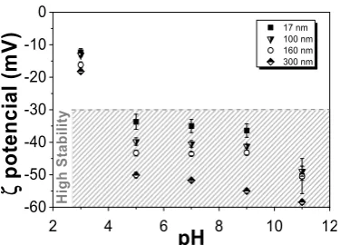
The morphology of the nanocomposites was assessed by SEM. Figure 3 shows the different
271
morphologies obtained after the different processing methods as well as the variations due to the
272
introduction of fillers with different diameters. Figure 3 shows the cross section (figure 3a-3c) of the
273
nanocomposites and electrospun fibres samples (figure 3d) with 16 wt% of SiNPs. Figures 3a and 3b
274
present the differences between the samples obtained at 90 ºC with SiNPs of different diameters,
275
showing that the higher diameter particles are well-dispersed in the PVDF polymer matrix, contrary
276
to the SiNPs with lower diameter that present particles agglomerates. Furthermore, a small porosity
277
is observed (figure 3a), which is in agreement with the literature [42].
278
It is to notice that the nanoparticles act as nucleation agents for crystallization in PVDF
279
composites [43], which can be verified with the results obtained, indicating a good interfacial
280
interaction between the PVDF chains and silica nanoparticles.
281
Figure 3a and 3c show the differences in composite morphology due to the crystallization
282
process. The samples obtained at 90 ºC (figure 3a and 3b) present a slightly more porous
283
morphology than the ones obtained at 210 0C (figure 3c).
284
285
Figure 3 - Cross section SEM micrographs of SiNPs/PVDF nanocomposite samples with
286
nanoparticles of different diameters and different processing conditions: a) F90-17NP, b) F90-300NP,
287
c) F210-17NP, d) R-17P.
288
289
Once the SiNPs with 17 nm do not show a suitable dispersion in the films, electrospinning has
290
been used in order to produce fibres with well dispersed particles. Relatively to the fibres (figure 3d),
291
smooth randomly oriented fibres with encapsulated particles are observed, with no particles at the
292
surface.
293
This result is confirmed by the confocal images represented in figure 4. It was observed that the
294
introduction of the particles increase the fibre diameter (243 ± 89 nm to 339 ± 92 nm). Oriented fibres
295
with SiNPs were also produced (data not shown), verifying also the particles encapsulation within
296
the fibres and fibre diameter of 683 ± 140 nm. The increase of fibre diameter with the incorporation of
297
the SiNPs is attributed to the higher viscosity of the solution, with also hinders fibre stretching by the
298
applied field. The higher diameter of the oriented fibres comparatively to the randomly oriented
299
301
Figure 4 - Representative confocal images of SiNPs/PVDF nanocomposites with different
302
morphologies: a) F210-17NP, b) F90-17NP, c) Ftamb-17P, d) O-17P and e) R-17P.
303
304
3.2.2. Confocal fluorescence microscopy of the nanocomposites
305
The incorporation of PDI in the silica nanoparticles can increase their application range, in
306
particular, for biomedical applications, as it allows their tracking and localization [37, 45]. In figure 4,
307
the green colour identifies the fluorescence of the nanoparticles, higher colour intensity indicates a
308
higher number of nanoparticles present. Figures 4a, 4b and 4c show that as the processing
309
temperature decreases, a larger aggregation of nanoparticles is observed. In figure 4a, where the
310
temperature is higher, more homogeneous samples were obtained.
311
Relatively to the oriented and random fibres, figure 4d and 4e, respectively, it is observed that
312
the nanoparticles are present and included within the fibres.
313
314
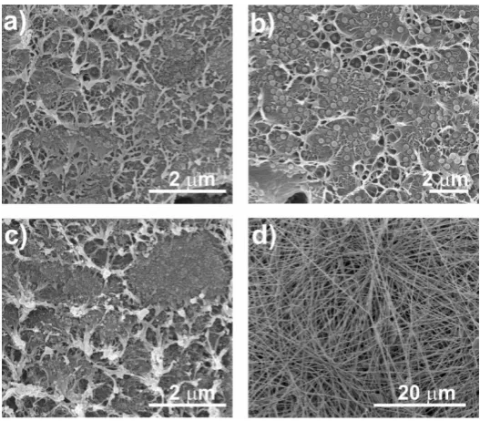
3.2.3. Wettability of the nanocomposites
315
Material surface characteristics are essential in demining cell response in tissue engineering
316
applications. In this sense, the static CA was measured on the different SiNPs/PVDF nanocomposites
317
and the values are presented in figure 5.
318
319
80 85 90 95 100 105 110 115
Co
nt
ac
t
ang
le
(
0)
Samples
F90-NP F90-17NP F90-100NP F90-160NP F90-300NP 80 100 120 140 160 180 200
C
o
ntact an
g
le
(
0)
F210-17NP F90-17NP FTamb-17P O-17P R-17P Samples
880
990
1460
320
Figure 5 - Contact angle of the SiNPs/PVDF nanocomposites: a) PVDF with the SiNPs with
321
different diameters processed at 90 0C and b) SiNPs/PVDF samples with silica nanoparticles (17 nm)
322
with different morphologies.
323
324
The introduction of the Si nanoparticles increases the CA values, independently of the diameter
325
of the silica nanoparticles [13], to around 100º excepting for the samples with silica nanoparticles
326
with the highest diameter (F90-300NP). This increase is attributed to the hydrophobic properties of
327
the silica nanoparticles [13]. The CA of the samples with the nanoparticles with the highest diameter
328
show a higher range of CA values, which is explained by the variation in the diameter of the
329
nanoparticles, as observed in figure 1. Regarding figure 5b, the CA for the composite samples with
330
the smallest silica nanoparticles show that the CA of PVDF fibres increases significantly when
331
compared to the one of PVDF films, and the CA of the oriented PVDF fibres is slightly higher than
332
the one for randomly oriented PVDF fibres, showing a contact angle of 146.0 ± 7.2º. These results
333
support the idea that the increase of the hydrophobicity of electrospun samples is mainly related to
334
the membrane morphology [8], the fibres being significantly more hydrophobic than films. In the
335
case of PVDF films, the CA is also higher for the films with higher porosity as already reported for
336
pristine films [38].
337
338
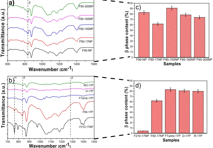
3.2.4. Structural properties and electroactive phase content of the nanocomposites
339
FTIR-ATR spectra allow to identify and quantify (equation 2) the polymer phase present in the
340
samples and, therefore, to evaluate possible modifications induced by the introduction of silica
341
nanoparticles (Figure 6).
342
600 800 1000 1200 1400 1600
F90-300NP F90-160NP F90-17NP F90-100NP β Tr ans m it ta nc e (a .u .)
Wavenumber (cm-1) F90-NP
d) c)
700 800 900 1000 1100 1200 1300 1400 1500
β α β NO-17P O-17P F90-17P FTamb-17P
Wavenumber (cm-1)
T ra n s m it ta n ce ( a.u .) F210-17NP b) a) a) 0 10 20 30 40 50 60 70 80 90 100 Samples
F90-NP F90-17NP F90-100NP F90-160NP F90-300NP
β p h ase con tent ( % ) 0 10 20 30 40 50 60 70 80 90 100 Samples
F210-17NP F90-17NP FTamb-17P O-17P R-17P
β p h as e co nt en t (% )
343
Figure 6 - FTIR spectra of a) neat PVDF and SiNPs/PVDF nanocomposites with silica
344
nanoparticles of different diameters processed at 90 ºC and b) different morphologies of SiNPs
345
nanocomposites prepared with the smallest nanoparticles. The β-phase content for the different
346
sample is represented in c) and d).
347
348
Figure 6a shows the FTIR spectra of the different samples prepared at 90 °C as well as the
349
corresponding quantification of the β-phase content (figure 6c, calculated after equation 1). The
350
characteristic bands of β PVDF (840 cm-1) is present in all samples, with low traces of α-PVDF (bands
351
at 766, 855 cm-1), with the exception of F210-17NP. This is mainly attributed to the processing
352
temperature [42], which mainly governs the solvent evaporation kinetics and the polymer
353
crystallization in the β phase for processing at temperatures below 90 °C [39]. The introduction of
354
SiNPs in PVDF does not significantly change the β-phase content, independently of the SiNPs
355
nanocomposites F90-17NP, F90-100NP, F90-160NP and F90-300NP, is 62 ± 2.5, 91 ± 3.6, 79 ± 3.1 and
357
74 ± 3, respectively (figure 6c). On the other hand, figure 6d shows that depending on the
358
nanocomposites morphology, the polymer crystallizes in different phase, mainly due to the different
359
processing conditions. Thus, electrospinning involves room temperature solvent evaporation and
360
polymer stretching during jet formation, both favorable conditions for the crystallization of the
361
polymer fibres in the β phase [44]. With respect to the films, the F210-17NP nanocomposite, which is
362
processed by a melting and recrystallization process, crystallizes in the α-phase and shows that the
363
addition of SiNPs does not induce the nucleation of the electroactive β-phase of the polymer, as
364
observed in previous study with Fe3O4 spherical nanoparticles [46]. On the other hand, the porous
365
samples, as well as the fibres, are prepared after solvent evaporation at room temperature,
366
conditions leading to the crystallization in the β-phase. This fact is not affected by the introduction of
367
the nanoparticles. Thus, it is concluded that the presence of the nanoparticles does not induce strong
368
interactions with the polymer chain, leading to the nucleation of a specific phase, as observed with
369
other fillers such as CoFe2O4 [47] and NaY zeolite [48]. Thus, processing temperature and
370
solvent/polymer ratio remains the main factor determining polymer phase content in those
371
composites [34, 39].
372
373
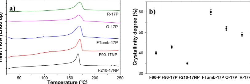
3.2.5. Thermal behaviour of the nanocomposites
374
The DSC scans allow to determine the melting temperature and the degree of polymer
375
crystallinity (figure 7).
376
377
50 100 150 200 250
H
eat
Flow (E
ndo up
)
Temperature (o C)
R-17P
O-17P
F90-17NP FTamb-17P
F210-17NP
30 40 50 60
F90-P F90-17P F210-17NP FTamb-17P O-17P R-17P
Crystall
inity
d
egre
e
(%)
Figure 7 - a) DSC thermographs and b) degree of crystallinity of the SiNPs/PVDF
378
nanocomposites with different morphologies and with the fillers of lowest average diameter.
379
380
All the samples show an endothermic peak around 168 ºC corresponding to the polymer
381
melting of the crystalline phase [39], thus, both processing conditions and incorporation of the filler
382
does not affect the melting temperature. The degree of crystallinity was calculated (equation 2) from
383
the enthalpy of the melting peak of the DSC thermograms. It is not notice that the samples prepared
384
by solvent evaporation at 90 ºC and after melting and recrystallization show a lower degree of
385
crystallinity than the samples prepared by solvent evaporation at room temperature, which also
386
includes the electrospun samples (figure 7b). The pristine PVDF film processed at 90 ºC shows a
387
degree of crystallinity of ≈40 %, which slightly increases with the introduction of the SiNPs and with
388
the size of the SiNPs, being 43% for F90-17NP and 55% for F90-160NP (data not shown). Relatively to
389
the different morphologies (figure 7a), the endothermic peak value is lower for the sample processed
390
at 210 ºC, indicating a lower degree of crystallinity if the sample, attributed to the fillers acting as
391
defects during the crystallization from the melt [49]. Inclusion of the nanoparticles in the fibres does
392
not significantly alters the crystallinity degree of the O-17P (52%) and R 17P (49%) with respect to the
393
pristine polymer oriented fibres (50% [8]).
394
The latter is ascribed to the combined effect of solvent evaporation at room temperature and
395
stretching during the crystallization process that overcome the effect of the presence of NP.
396
397
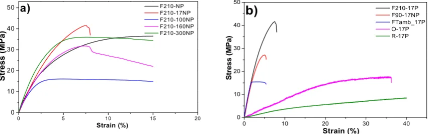
3.2.6. Mechanical properties of the nanocomposites
398
The mechanical properties of the materials are essential parameters to design a scaffold suitable
399
for tissues with different mechanical characteristics. The characteristic mechanical strain-stress
400
curves of samples with different morphology, filler type and content are presented in figure 8.
401
Figure 8a shows the stress-strain curves for the nanocomposites prepared with fillers with
402
different average diameter after a melting process and figure 8b refers to the nanocomposites with
403
the same SiNPs (17 nm) after different processing conditions. Independently of the filler average
404
diameter or processing conditions all samples show the typical mechanical behaviour of PVDF [50]
405
characterized by the elastic region, yielding and plastic region, i.e. the typical behaviour of a
406
thermoplastic elastomer.
407
0 5 10 15 20
0 10 20 30 40 50
Strain (%)
Str
e
ss
(MPa)
F210-NP F210-17NP F210-100NP F210-160NP F210-300NP
a)
0 10 20 30 40
0 10 20 30 40 50
S
tress (
M
P
a)
Strain (%)
F210-17P F90-17NP FTamb_17P O-17P R-17P
b)
Figure 8 - Stress-Strain curves for a) SiNPs/PVDF nanocomposites with different SiNPs average
408
diameters within the PVDF matrix and b) for nanocomposites obtained after different processing
409
conditions.
410
411
The Young modulus of the samples was calculated from the linear zone of elasticity between 0
412
and 1% strain, as presented in table 3.
413
414
Table 3 - Young modulus of the SiNPs/PVDF nanocomposites varying the average diameters of the
415
SiNPs and the processing method. The values shown as mean ± SD.
416
417
418
419
420
421
422
423
The characteristic features of the strain-stress curves are similar for all the materials,
424
demonstrating that the mechanical characteristics are not strongly dependent on nanoparticle
425
diameter. Further, the introduction of particles with different diameters does not significantly affect
426
the Young modulus of the pristine PVDF (F210-NP) - 0.94 ± 0,04 GPa. However, a slight
427
Samples E (GPa)
F210-17NP 1.05 ± 0.06
F90-17NP 0.95 ± 0.04
FTamb-17P 0.74 ± 0.07
O-17P 0.082 ± 0.012
R-17P 0.032 ± 0.002
Samples E (GPa)
F210-NP 0.94 ± 0.04
F210-17NP 1.05 ± 0.06
F210-100NP 0.89 ± 0.09
F210-160NP 0.86 ± 0.02
F210-300NP 0.88 ± 0.08
D
iff
er
en
t
p
ro
ductio
n m
et
h
ods
Increasing
N
P
s
d
improvement of the Young modulus is observed for the samples prepared with smaller silica
428
nanoparticles (F210-17NP): 1.05 ± 0.06 GPa, this is in line with reports showing that the modulus
429
increases as the particle size decreases [51]. Relatively to the different production methods for the
430
polymer films, F210-NP, F90-17NP and Ftamb-17P, it is observed that the more porous is the
431
structure, the lower is the Young modulus, 0.83 ± 0.16 GPa for FTamb-17P. On the other hand,
432
oriented fibres (O-17P) show higher Young modulus (0.082 ± 0.012 GPa) than the random fiber
433
samples (R-17P) (0.032 ± 0.002 GPa) due to the larger number of fibres along the stretch direction [8].
434
Relatively to the other samples, the production method has a relevant influence on their
435
mechanical response, as the samples prepared at room temperature by solvent evaporation showing
436
lower Young modulus than those obtained at 210 ºC, due to the porous nature of the former and the
437
compact structure of the later, as was also visible in the SEM images (figure 3).
438
439
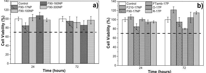
3.3. Cell culture studies
440
In order to explore the potential use of the developed materials in tissue engineering
441
applications, it is necessary to evaluate the putative cytotoxicity of the samples. The study of
442
metabolic activity of C2C12 myoblasts, evaluated with the MTS assay, was applied to all samples
443
and the results for 24 and 72 h are presented in figure 9. Thus, the effects associated with introducing
444
fluorescent SiNP with different sizes is analyzed as well as the effect of the different
445
microstructures/morphologies.
446
447
0 20 40 60 80 100 120 140
Time (hours) 24 72
C
ell
V
ia
b
ility
(%
)
Control F90-160NP
F90-17NP F90-300NP
F90-100NP
a)
0 20 40 60 80 100 120 140
Control FTamb-17P
F210-17NP O-17P
F90-17NP R-17P
C
ell V
ia
b
ili
ty
(
%
)
Time (hours) 24 72
b)
Figure 9 - Cytotoxicity indirect test of a) samples prepared with nanoparticles of different
448
diameters and prepared by solvent evaporation at 90 ºC and b) samples prepared with SiNPs of
449
17 nm diameter after different processing methods and therefore with different morphologies.
450
451
It has been already reported that PVDF is biocompatible and shows no cytotoxicity to C2C12
452
cells for 24 or 72 h [24, 33]. The SiNPs are also biocompatible for many cells including C2C12
453
myoblasts [52-54].
454
Thus, figure 9 shows that none of the samples are cytotoxic, independently of the nanoparticle
455
diameter and of the material morphology. It is to notice that despite both materials being
456
biocompatible, the result is not evident, as polymer-filler interface effects or solvent retained in the
457
nanoparticles or in the interface areas, can lead to cytotoxic effects. According to the ISO standard
458
10993-5, samples are considered cytotoxic when cells suffer a viability reduction larger than 30%.
459
The measured cell viability values are all higher than 70%, confirming the cytocompatibility of the
460
SiNPs/PVDF nanocomposites.
461
C2C12 myoblasts were used in previous studies to analyze cell proliferation of cultures grown
462
on porous [55] and non-porous [33] PVDF films as well as fibres [33], with the verification that
463
C2C12 cells proliferate better on piezoelectric β-PVDF “poled” samples. The samples obtained in
464
this work were studied to determine the suitability for tissue engineering applications, namely
465
The MTS (figure 10), immunofluorescence (figure 11) and SEM (figure 12) assays were used to
467
assess cell viability and morphology in the different samples. Relatively to the proliferation results
468
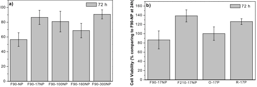
(Figure 10), the cell viability has been obtained in relation to the sample of F90-NP at 24 h.
469
470
𝐶𝑒𝑙𝑙 𝑉𝑖𝑎𝑏𝑖𝑙𝑖𝑡𝑦 (%) = 𝐴𝑏𝑠𝑜𝑟𝑏𝑎𝑛𝑐𝑒 𝑜𝑓 𝑠𝑎𝑚𝑝𝑙𝑒𝑠 𝑎𝑡 72ℎ
𝐴𝑏𝑠𝑜𝑟𝑏𝑎𝑛𝑐𝑒 𝑜𝑓 𝐹90-𝑁𝑃 𝑎𝑡 24ℎ × 100 − 𝑐𝑒𝑙𝑙 𝑣𝑖𝑎𝑏𝑖𝑙𝑖𝑡𝑦 𝑜𝑓 𝐹90-𝑁𝑃 𝑎𝑡 24ℎ (3)
471
472
Figure 10 shows that cell viability of the samples increases after 72 h of cell culture,
473
independently of the SiNPs diameters (figure 10a) and the morphology of the materials (figure 10b),
474
when compared with the sample without particles (F90-NP). No significant differences are observed
475
between the samples and the negative control (F90-NP), revealing that C2C12 myoblast proliferation
476
is not affected by the presence of SiNPs in the PVDF matrix. In fact, it has been reported that SiNPs
477
included in different polymers improves cell attachment and proliferation, and enhances cellular
478
processes [56-57], which is in agreement with the obtained results.
479
480
0 20 40 60 80 100
Ce
ll
Vi
ab
ilit
y (
%
co
m
pa
rin
g
t
o
F9
0-NP
a
t 2
4
h
)
72 h
F90-NP F90-17NP F90-100NP F90-160NP F90-300NP a)
0 20 40 60 80 100 120 140
160 b)
R-17P O-17P
F210-17NP
Ce
ll V
iab
ili
ty
(% c
o
m
p
arin
g
to
F
90
-NP
at 2
4h
)
72 h
F90-17NP
Figure 10 - Cell proliferation of C2C12 cells seeded on a) SiNPs/PVDF samples prepared at
481
90 0C with different sized nanoparticles and b) SiNPs/PVDF samples with different morphologies.
482
483
Cell cytoskeleton morphology, viability and adhesion were analyzed by fluorescence
484
microscopy for porous and non porous films and SEM for fibre samples.
485
Independently of the nanoparticles diameters and the sample morphology, it is observed that
486
the cell behavior is similar. Bigger cell agglomerates are observed with increasing nanoparticles
487
diameter (which also show larger nanoparticle agglomerates) on the samples (figure 11 a-d). This
488
fact is associated with the interaction between serum proteins and nanoparticles present on the
489
PVDF matrix, as it has been reported that negative surface charge enhance the adsorption of proteins
490
with isoelectric point more than 5.5 such as immunoglobulin G (IgG) that can be important for
491
C2C12 myoblasts [58-59]. Cell cultures on PVDF fibres prepared with the smaller silica nanoparticles
492
were analyzed by SEM and figure 12 shows the cell morphology of C2C12 cells after 72 h of cell
493
culture on oriented and random PVDF fiber nanocomposites.
494
496
Figure 11- Representative images of C2C12 myoblast culture after 72 h on a) F90-17NP, b)
497
F90-100NP, c) F90-160NP, d) F90-300NP, e) F210-17NP and f) FTamb-17P samples (nucleus stained
498
with DAPI-blue and cytoskeleton stained with FITC-green). Scale bar = 100 µm for all the samples.
499
500
These representative images demonstrate that in the presence of fibrillar microstructure the
501
muscle cells orientate their cytoskeleton along the fibres, which is in agreement with the literature
502
[33]. In this way, in the presence of oriented fibres, the cells share a similar architecture to the natural
503
muscle cells in living systems.
504
505
506
Figure 12 - Cell morphology obtained by SEM of C2C12 myoblasts seeded on PVDF fibres: a)
507
O-17P and b) R-17P, after 3 days of culture. The scale bar is 200 µm for all samples.
508
509
a)
b)
a)
b)
c)
d)
e)
f)
Thus, the overall results prove the potential of the use of SiNPs/PVDF piezoelectric
510
nanocomposites for muscle tissue engineering. Physical and chemical stimuli are important factors
511
to obtain tissues with characteristics similar to those of natural living tissues in the human body,
512
developing therefore specific biomimetic microenvironments for different tissues, attending their
513
specific biophysico-chemical needs. The developed platform presents nanocomposites with different
514
morphologies (membranes and fibres), piezoelectric β phase and SiNPs diameter (from 17 to
515
300 nm), which makes it an interesting and complete platform for tissue engineering.
516
Furthermore, this platform will allow further studies applying mechanical stimuli on the
517
nanocomposites obtained in this work with specific bioreactors [31] applying mechanical and/or
518
mechanoelectrical stimuli. It may also take advantage of the SiNPs capacity to include specific
519
biomolecules or to develop drug delivery systems, or more specifically, differentiation factors to
520
promote directed myogenic differentiation. This will allow not only a deeper knowledge of the
521
necessary stimuli for muscle tissue regeneration, but also more effective therapies.
522
523
5. Conclusions
524
Different parameters are important for tissue engineering, such as materials morphology,
525
porosity and the PVDF electroactive phase, are modified in the obtained membranes.
526
Different diameters of silica nanoparticles have been introduced within PVDF polymer matrix
527
to obtain multifunctional samples for tissue engineering applications.
528
It is observed that the introduction of the SiNPs fillers in the PVDF matrix decreases its
529
wettability. Further, it is shown that the filler diameter does not significantly affects the properties of
530
the polymer matrix, such as physico-chemical, thermal and mechanical properties.
531
Cytotoxicity assays with C2C12 cells show no cytotoxic associated with neat PVDF and
532
composites with different SiNPs diameters and sample morphologies.
533
Thus, it is demonstrated that the developed platform of PVDF materials with silica
534
nanoparticles demonstrates a large potential for tissue engineering applications allowing to develop
535
electromechanically active microenvironments with different morphologies with SiNPs allowing
536
protein functionalization and/or controlled release of specific drugs and/or growth or differentiation
537
factors according the targeted application.
538
Author Contributions: S.L.-M. conceived and designed the project. S.R. and T.R. contributed to the processing
539
and characterization of the particles. J.P.C. and C.B. contributed to the characterization of the nanoparticles. S.R.
540
and D.M.C. contributed to the processing and characterization of the samples in the different morphologies.
541
S.R. was in charge of the cell culture assays and their characterization and interpretation. C.R. contributed to the
542
cell culture assays and the interpretation of the cell culture assays. All authors contributed to the evaluation and
543
interpretation of the data, as well as to the writing of the manuscript. All authors agree with the paper
544
submission.
545
546
Funding: This work was supported by the Portuguese Foundation for Science and Technology (FCT) in the
547
framework of the Strategic Funding UID/FIS/04650/2013 and UID/BIA/04050/2013
548
(POCI-01-0145-FEDER-007569) and project POCI-01-0145-FEDER-028237 funded by national funds through
549
Fundação para a Ciência e a Tecnologia (FCT) and by the ERDF through the COMPETE2020 - Programa
550
Operacional Competitividade e Internacionalização (POCI); and also under the scope of the strategic funding of
551
UID/BIO/04469 unit and COMPETE 2020 (POCI-01-0145-FEDER-006684) and BioTecNorte operation
552
(NORTE-01-0145-FEDER-000004) funded by the European Regional Development Fund under the scope of
553
Norte2020 - Programa Operacional Regional do Norte. The authors also thank the FCT for the
554
SFRH/BD/111478/2015 (S.R.), SFRH/BPD/96707/2013 (T.R.), SFRH/BPD/90870/2012 (C.R.) and
555
SFRH/BPD/121526/2016 (D.C) grants. The authors acknowledge funding by the Spanish Ministry of Economy
556
and Competitiveness (MINECO) through the project MAT2016-76039-C4-3-R (AEI/FEDER, UE) and from the
557
Basque Government Industry Department under the ELKARTEK and HAZITEK programs.
558
559
Acknowledgments: The SEM measurements have been conducted at Center of Biological Engineering (CEB),
560
Braga, Portugal. The authors thank CEB for offering access to their instruments and expertise.
Conflicts of Interest: The authors declare no conflict of interest.
562
References
563
1. Camargo, P.H.C.; Satyanarayana, K.G.; Wypych, F. Nanocomposites: Synthesis, structure, properties and
564
new application opportunities. Mater. Res.-Ibero-Am. J. Mater. 2009, 12, 1-39.
565
2. Muller, K.; Bugnicourt, E.; Latorre, M.; Jorda, M.; Sanz, Y.E.; Lagaron, J.M.; Miesbauer, O.; Bianchin, A.;
566
Hankin, S.; Bolz, U., et al. Review on the processing and properties of polymer nanocomposites and
567
nanocoatings and their applications in the packaging, automotive and solar energy fields. Nanomaterials 2017, 7,
568
.E74
569
3. Raji, M.; Mekhzoum, M.E.M.; Rodrigue, D.; Qaiss, A.E.K.; Bouhfid, R. Effect of silane functionalization on
570
properties of polypropylene/clay nanocomposites. Compos. B: Eng. 2018, 146, 106-115.
571
4. Ribeiro, S.; Costa, P.; Ribeiro, C.; Sencadas, V.; Botelho, G.; Lanceros-Méndez, S. Electrospun
572
styrene-butadiene-styrene elastomer copolymers for tissue engineering applications: Effect of
573
butadiene/styrene ratio, block structure, hydrogenation and carbon nanotube loading on physical properties
574
and cytotoxicity. Compos. B: Eng. 2014, 67, 30-38.
575
5. Narayanan, K.B.; Han, S.S. Dual-crosslinked poly(vinyl alcohol)/sodium alginate/silver nanocomposite
576
beads - a promising antimicrobial material. Food Chemistry 2017, 234, 103-110.
577
6. Ribeiro, C.; Sencadas, V.; Correia, D.M.; Lanceros-Mendez, S. Piezoelectric polymers as biomaterials for
578
tissue engineering applications. Colloids Surf. B 2015, 136, 46-55.
579
7. Cardoso, V.F.; Correia, D.M.; Ribeiro, C.; Fernandes, M.M.; Lanceros-Méndez, S. Fluorinated polymers as
580
smart materials for advanced biomedical applications. Polymers 2018, 10, 161.
581
8. Maciel, M.M.; Ribeiro, S.; Ribeiro, C.; Francesko, A.; Maceiras, A.; Vilas, J.L.; Lanceros-Méndez, S. Relation
582
between fiber orientation and mechanical properties of nano-engineered poly(vinylidene fluoride) electrospun
583
composite fiber mats. Compos. B: Eng. 2018, 139, 146-154.
584
9. Cardoso, V.F.; Francesko, A.; Ribeiro, C.; Bañobre-López, M.; Martins, P.; Lanceros-Mendez, S. Advances
585
in magnetic nanoparticles for biomedical applications. Advanced Healthcare Materials 2017, 7, 1700845.
586
10. Xu, D.; Cheng, X.; Banerjee, S.; Huang, S. Dielectric and electromechanical properties of modified
587
cement/polymer based 1-3 connectivity piezoelectric composites containing inorganic fillers. Compos. Sci.
588
Technol. 2015, 114, 72-78.
589
11. Li, Y.; Yang, X.Y.; Feng, Y.; Yuan, Z.Y.; Su, B.L. One-dimensional metal oxide nanotubes, nanowires,
590
nanoribbons, and nanorods: Synthesis, characterizations, properties and applications. Crit. Rev.Solid State Mater.
591
Sci. 2012, 37, 1-74.
592
12. Chen, L.; Jia, Z.; Tang, Y.; Wu, L.; Luo, Y.; Jia, D. Novel functional silica nanoparticles for rubber
593
vulcanization and reinforcement. Compos. Sci. Technol.2017, 144, 11-17.
594
13. Ribeiro, T.; Baleizao, C.; Farinha, J.P.S. Functional films from silica/polymer nanoparticles. Materials 2014,
595
7, 3881-3900.
596
14. Asefa, T.; Tao, Z.M. Biocompatibility of mesoporous silica nanoparticles. Chem. Res. Toxicol. 2012, 25,
597
2265-2284.
598
15. Rodrigues, A.S.; Ribeiro, T.; Fernandes, F.; Farinha, J.P.S.; Baleizao, C. Intrinsically fluorescent silica
599
nanocontainers: A promising theranostic platform. Microsc. Microanal. 2013, 19, 1216-1221.
600
16. Jiao, J.; Liu, C.; Li, X.; Liu, J.; Di, D.; Zhang, Y.; Zhao, Q.; Wang, S. Fluorescent carbon dot modified
601
mesoporous silica nanocarriers for redox-responsive controlled drug delivery and bioimaging. J. Colloid Interface
602
Sci. 2016, 483, 343-352.
603
17. Burns, A.; Ow, H.; Wiesner, U. Fluorescent core-shell silica nanoparticles: Towards "Lab on a particle"
604
Architectures for nanobiotechnology. Chem. Soc. Rev. 2006, 35, 1028-1042.
605
18. Chen, F.; Hableel, G.; Zhao, E.R.; Jokerst, J.V. Multifunctional nanomedicine with silica: Role of silica in
606
nanoparticles for theranostic, imaging, and drug monitoring. J. Colloid Interface Sci. 2018, 521, 261-279.
607
19. Yan, J.; Estevez, M.C.; Smith, J.E.; Wang, K.; He, X.; Wang, L.; Tan, W. Dye-doped nanoparticles for
608
bioanalysis. Nano Today 2007, 2, 44-50.
609
20. Cardoso, V.F.; Irusta, S.; Navascues, N.; Lanceros-Mendez, S. Comparative study of sol-gel methods for
610
the facile synthesis of tailored magnetic silica spheres. Mater. Res. Express 2016, 3, 075402.
611
21. Slowing, I.I.; Vivero-Escoto, J.L.; Trewyn, B.G.; Lin, V.S.Y. Mesoporous silica nanoparticles: Structural
612
design and applications. J. Mater. Chem. 2010, 20, 7924-7937.
22. Liong, M.; Lu, J.; Kovochich, M.; Xia, T.; Ruehm, S.G.; Nel, A.E.; Tamanoi, F.; Zink, J.I. Multifunctional
614
inorganic nanoparticles for imaging, targeting, and drug delivery. Acs Nano 2008, 2, 889-896.
615
23. Bharti, C.; Nagaich, U.; Pal, A.K.; Gulati, N. Mesoporous silica nanoparticles in target drug delivery
616
system: A review. Int. J. Pharm. Invest. 2015, 5, 124-133.
617
24. Parssinen, J.; Hammaren, H.; Rahikainen, R.; Sencadas, V.; Ribeiro, C.; Vanhatupa, S.; Miettinen, S.;
618
Lanceros-Mendez, S.; Hytonen, V.P. Enhancement of adhesion and promotion of osteogenic differentiation of
619
human adipose stem cells by poled electroactive poly(vinylidene fluoride). J. Biomed. Mater. Res. A 2015, 103,
620
919-928.
621
25. Gilbert, J.R.; Meissner, G. Sodium-calcium ion-exchange in skeletal-muscle sarcolemmal vesicles. J. Membr.
622
Biol. 1982, 69, 77-84.
623
26. Brito-Pereira, R.; Ribeiro, C.; Lanceros-Mendez, S.; Martins, P. Magnetoelectric response on terfenol-d/
624
p(vdf-trfe) two-phase composites. Compos. B: Eng. 2017, 120, 97-102.
625
27. Ribeiro, C.; Correia, V.; Martins, P.; Gama, F.M.; Lanceros-Mendez, S. Proving the suitability of
626
magnetoelectric stimuli for tissue engineering applications. Colloids Surf. B 2016, 140, 430-436.
627
28. Ribeiro, S.; Correia, D.M.; Ribeiro, C.; Lanceros-Méndez, S. Electrospun polymeric smart materials for
628
tissue engineering applications. In Electrospun biomaterials and related technologies, Almodovar, J., Ed. Springer
629
International Publishing: Cham, 2017; pp 251-282.
630
29. Cardoso, V.F.; Ribeiro, C.; Lanceros-Mendez, S. Metamorphic biomaterials. In Bioinspired materials for
631
medical applications, 2016; pp 69-99.
632
30. Lee, Y.S.; Collins, G.; Arinzeh, T.L. Neurite extension of primary neurons on electrospun piezoelectric
633
scaffolds. Acta Biomaterialia 2011, 7, 3877-3886.
634
31. Ribeiro, C.; Moreira, S.; Correia, V.; Sencadas, V.; Rocha, J.G.; Gama, F.M.; Ribelles, J.L.G.;
635
Lanceros-Mendez, S. Enhanced proliferation of pre-osteoblastic cells by dynamic piezoelectric stimulation. Rsc
636
Adv. 2012, 2, 11504-11509.
637
32. Ribeiro, C.; Parssinen, J.; Sencadas, V.; Correia, V.; Miettinen, S.; Hytonen, V.P.; Lanceros-Mendez, S.
638
Dynamic piezoelectric stimulation enhances osteogenic differentiation of human adipose stem cells. J.Biomed.
639
Mater.Res. A 2015, 103, 2172-2175.
640
33. Martins, P.M.; Ribeiro, S.; Ribeiro, C.; Sencadas, V.; Gomes, A.C.; Gama, F.M.; Lanceros-Mendez, S. Effect
641
of poling state and morphology of piezoelectric poly(vinylidene fluoride) membranes for skeletal muscle tissue
642
engineering. Rsc Adv. 2013, 3, 17938-17944.
643
34. Ribeiro, C.; Costa, C.M.; Correia, D.M.; Nunes-Pereira, J.; Oliveira, J.; Martins, P.; Gonçalves, R.; Cardoso,
644
V.F.; Lanceros-Méndez, S. Electroactive poly(vinylidene fluoride)-based structures for advanced applications.
645
Nat. Protoc. 2018, 13, 681-704.
646
35. Ribeiro, T.; Baleizão, C.; Farinha, J.P.S. Synthesis and characterization of perylenediimide labeled
647
core-shell hybrid silica-polymer nanoparticles. J. Phys. Chem. C 2009, 113, 18082-18090.
648
36. Santiago, A.M.; Ribeiro, T.; Rodrigues, A.S.; Ribeiro, B.; Frade, R.F.M.; Baleizão, C.; Farinha, J.P.S.
649
Multifunctional hybrid silica nanoparticles with a fluorescent core and active targeting shell for fluorescence
650
imaging biodiagnostic applications. Eur. J. Inorg. Chem. 2015, 2015, 4579-4587.
651
37. Ribeiro, T.; Raja, S.; Rodrigues, A.S.; Fernandes, F.; Baleizão, C.; Farinha, J.P.S. Nir and visible
652
perylenediimide-silica nanoparticles for laser scanning bioimaging. Dyes Pigm. 2014, 110, 227-234.
653
38. Lopes, A.C.; Ribeiro, C.; Sencadas, V.; Botelho, G.; Lanceros-Mendez, S. Effect of filler content on
654
morphology and physical-chemical characteristics of poly(vinylidene fluoride)/nay zeolite-filled membranes. J.
655
Mater. Sci. 2014, 49, 3361-3370.
656
39. Martins, P.; Lopes, A.C.; Lanceros-Mendez, S. Electroactive phases of poly(vinylidene fluoride):
657
Determination, processing and applications. Prog. Polym. Sci. 2014, 39, 683-706.
658
40. Stober, W.; Fink, A.; Bohn, E. Controlled growth of monodisperse silica spheres in micron size range. J.
659
Colloid Interface Sci.1968, 26, 62-69.
660
41. Martins, P.; Caparros, C.; Gonçalves, R.; Martins, P.M.; Benelmekki, M.; Botelho, G.; Lanceros-Mendez, S.
661
Role of nanoparticle surface charge on the nucleation of the electroactive β-poly(vinylidene fluoride)
662
nanocomposites for sensor and actuator applications. J. Phys. Chem. C 2012, 116, 15790-15794.
663
42. Ferreira, J.C.C.; Monteiro, T.S.; Lopes, A.C.; Costa, C.M.; Silva, M.M.; Machado, A.V.; Lanceros-Mendez, S.
664
Variation of the physicochemical and morphological characteristics of solvent casted poly(vinylidene fluoride)
665
along its binary phase diagram with dimethylformamide. J. Non-Cryst. Solids 2015, 412, 16-23.