Installing
and Getting Started
76-110-0675/F Release 6, Issue 1
Installing
and Getting Started
NOTICE
This publication refers to Telrad’s ACD IQ package running on Telrad’s DIGITAL KEY BX system, Releases SB-6 and up, or on Telrad’s DIGITAL 400 system, Releases DB-6 and up, as of Sep-tember, 1998.
This publication describes the operation of the agent’s position, using any Telrad DIGITAL telephone, although preferably one with a display.
Telrad reserves the right to modify the equipment and the soft-ware described herein without prior notice. However, changes made to the equipment or to the software described herein do not necessarily render this publication invalid.
Section 1
INTRODUCTION
1.1
ABOUT THE
ACD IQ
SYSTEM
ACD IQ is a comprehensive telephone management sys-tem designed to monitor the activities of a Call Center. While monitoring Call Center activities, the system gener-ates reports summarizing the past performance of the sys-tem over a given time period, and provides statistical analyses of the Call Center system behaviour, within a specified period.
The ACD IQ system enables management to accurately assess Call Center activity trends. On the basis of this in-formation, management can provide the most efficient per-sonnel allocation plan to meet the Call Center
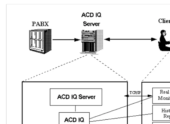
Figure 1-1 displays the relationship between the ACD IQ server database and one client station.
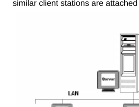
Figure 1-2 below displays a configuration in which several similar client stations are attached to the server:
Figure 1-2: Typical Server - Multi-Client Relationship
In this example, the server is attached to several client sta-tions. In addition to the server’s ACD IQ installation, each client station has ACD IQ client applications installed on its hard disk. On one client station, only the Real-Time Moni-toring and the Wall Board Administration applications have been installed.
This guide describes the installation procedures to be fol-lowed for the following three ACD IQ installation configura-tions:
• Network Client-Server Configuration - For this
• Standalone Configuration - For this configuration, the
requirements and installation procedure to be per-formed on the standalone computer, are described. • Real-Time Client Configuration - For this
configura-tion, the requirements and installation procedures required for a Real-Time client configuration are described.
1.2
SCOPE OF THIS GUIDE
This guide describes how to install the software necessary to run the Telrad ACD IQ system. It describes the installa-tion procedures for the three ACD IQ installainstalla-tion configura-tions, described in the previous section.
It is intended for the PBX technician who installs the ACD IQ system on a client/server network or on a standalone computer. It is assumed that the reader is familiar with the physical hardware setup of the ACD IQ system and the physical connections between the system’s units.
The guide is also intended to provide “getting started” infor-mation for Call Center administrators and other users of the system.
NOTES
This guide is not intended as a user guide for the ACD IQ system. It does not describe how to use the ACD IQ applica-tions in detail. For comprehensive infor-mation on how to use the ACD IQ applications, refer to the context sensi-tive on-line help system provided.
For the latest information on the ACD IQ system, please refer to the read.me file provided with the installation CD.
1.3
HOW IS THIS GUIDE ORGANIZED
This guide is divided into the following four chapters: Section 1: Introduction, gets you acquainted with
the ACD IQ system, and explains the pur-pose, structure and relevant information related to this guide.
Section 2: Installation Guide, provides step-by-step
instructions on how to install ACD IQ on each platform available, including the screens presented during the installation procedure.
Section 3: Getting Started, provides a basic
intro-duction to the ACD IQ applications and dis-plays sample screens for each application. Section 4: Troubleshooting, lists the problems that
1.4
TYPOGRAPHICAL CONVENTIONS
IN THIS GUIDE
Various typographical conventions are used throughout this guide to help you follow the text. The following kinds of formatting identify specific information:
Arial font Words that appear in this font are actual words that appear in the windows and di-alog boxes of the software applications. Italic font Apart from the name of the product itself,
words that appear in italics indicate cross-references to other sections or figures within the Guide.
Note: Important notes are preceded by the word
Note: presented in bold typeface, with
lines above and below. Arrow bullet
and bold type
Text that is bold and preceded by an ar-row bullet indicates the start of a proce-dure or task that you can perform. Black square
bullet
Text that is preceded by a black square bullet indicates that this task requires only one step.
Bulleted List Text that is preceded by a black diamond bullet indicates a list of points in no partic-ular order.
Numbered List
Text that is preceded by a number indi-cates a list of sequential points or a series of steps you must perform in order.
<Text en-closed by ar-row-shaped brackets and in Arial font>
1.5
ABBREVIATIONS & TERMINOLOGY
For a complete list and explanation of ACD IQ and telepho-ny terminology, refer to the glossary provided in the ACD IQ context sensitive on-line help system.
The following terms are used frequently throughout this guide:
PBX/PABX Private Branch eXchange/Private Auto-matic Branch eXchange.
A
Section 2
INSTALLATION GUIDE
2.1
PREPARING THE SYSTEM
This chapter describes the step-by-step procedure for in-stalling the ACD IQ system on each available platform. At each step, the appropriate windows or screens are de-scribed. The installation process is basically an automatic procedure, requiring minimum intervention on the techni-cian’s part.
NOTE
Before beginning the installation pro-cess, make sure you have attached the appropriate lock device to the server and client computers (one for the server and one for each client computer), where necessary. Without the lock device, you will not be able to install the system.
Following is a summarized checklist of the operations to be performed in order to install and run the ACD IQ pro-gram:
• Set up the computers.
• Set up the network and test it using the assigned net-work TCP/IP addresses.
• Test the connectivity of the computers and server using the PING utility.
• Install the client software and check that it runs correctly. Make sure that the server is running before checking. • Perform the initial administration process, as described
in Section 3.3 Setting the Parameters for a First Time Installation.
2.2
HARDWARE REQUIREMENTS
This section lists the minimum hardware requirements nec-essary to install and run the ACD IQ system, for the server, client and network computers.
2.2.1
Server
The server computer must include the following hardware: • CPU Pentium 200 MHz or higher.
• 64 MB RAM or higher.
• An NT supported Network Interface Card.
• An NT supported modem (for remote maintenance). The modem must be configurable as COM3.
• Two free serial ports (the first is for the PABX connec-tion, the second is for the Wall Board connection). • ACD IQ Server Lock Device (Hasp).
2.2.2
Client
The client computer must be a standard PC computer with the following hardware:
• CPU Pentium. • 16 MB RAM.
• Network Interface Card.
• ACD IQ Client Lock Device (Hasp).
2.2.3
Network
2.3
SOFTWARE REQUIREMENTS
This section defines the minimum software requirements for installing and running the ACD IQ system, for a server or standalone system, or client station.
2.3.1
Server or Standalone System
The server or standalone computer must be configured with the following software:
• Windows NT Workstation 4.0.
NOTE
The Sybase SQL Anywhere 5.5 software is installed by the ACD IQ installation program.
2.3.2 Client Station
• DOS (6.2 or above) plus Windows 3.11, or Windows 95.
NOTE
The Sybase SQL Anywhere software is installed by the ACD IQ installation pro-gram.
2.4
THE INSTALLATION PROCEDURE
The ACD IQ system can be configured to run in one of the following configurations:
• Standalone Server and Client Configuration: In this
configuration, the server and client software are installed on the same Win NT Workstation computer. • Network Server and Clients Configuration: In this
The installation procedure automatically identifies the type of installation that is required, by reading the information found on the computer’s lock device.
You will need the following items to install ACD IQ: • ACD IQ Installation CD-ROM.
• ACD IQ Server Lock Device (one).
• ACD IQ Client Lock Device (one for each network cli-ent).
2.4.1 Installing the ACD IQ Server
The following installation procedure is identical for all the available configurations.
To install the ACD IQ Server system:
1. Ensure that all the prerequisite software required for the server has been installed (see Section 2.3.1 Server or Standalone System).
2. Connect the PBX to a COM port on the Server (COM1 is the default), check the date/time on both (the PBX and the Server) and synchronize them if needed. 3. Connect the Wall Board to another COM port on the
Server.
4. Install the Server Lock Device on the parallel port. 5. Insert the ACD IQ installation CD-ROM into the CD
Drive.
6. The CD-ROM is incorporated with autorun directives so by default it should start the setup process when detected. If for some reason there is a need to activate it manually, the SETUP32.EXE program located on the ACDIQ directory of the CD-ROM should be started. 7. If this is a first installation, then the server will probably
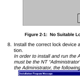
If the device driver is installed, but no lock device is found, or a lock device which is not for a Server station is installed, then the following message will be displayed.
Figure 2-1: No Suitable Lock Device Found
8. Install the correct lock device and restart the installa-tion.
In order to install and run the ACD IQ server, the user must be the NT “Administrator” user. If the user is not the Administrator, the following message is displayed:
Figure 2-2: User is not the NT Administrator
NOTE
9. If a valid Server Lock Device is found, the following wel-come message is displayed:
Figure 2-3: The welcom Message
NOTE
This message changes according to the installation procedure selected by the lock device.
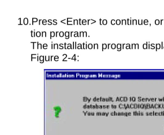
10.Press <Enter> to continue, or <Esc> to exit the installa-tion program.
The installation program displays the prompt shown in Figure 2-4:
Figure 2-4: Selecting the ACD IQ Drive
11.By default, ACD IQ is installed on drive C: under the directory C:\ACDIQ.
To install ACD IQ on drive C:
• Select Use the default drive.
To install ACD IQ on a different drive:
• Select Change the drive and select the required drive from the list.
In order to run properly, ACD IQ must know the administra-tor password. The default is no password. You can change it in the following message box that is displayed:
12.The current TCP/IP address of the server is displayed and you are prompted to confirm or change it as required, as shown in Figure 2-6.
Figure 2-6: Confirming the Server IP Address
13.If you choose to change the IP addresses, you are prompted for the IP address of the server station. If you are not sure of the correct IP address, please ask the network administrator.
Figure 2-7: Changing the Server IP Address
than one ACD IQ Network server on the same network.
Figure 2-8: Changing the Server Name
15.By default, the installation procedure installs the Sybase SQL Anywhere 5.5 Database software in the directory C:\SQLANY50. You may now change this directory (though it is not recommended):
Figure 2-9: Entering the SQL Directory
path is used by the server computer.
Figure 2-10: Confirming the Server Backup Database Path
After the Sybase SQL Anywhere 5.5 software has been lo-cated, for a server installation, the following message is dis-played:
Figure 2-11: The Ready for Installation Message
NOTE
This message changes according to the installation procedure selected by the lock device.
NOTE
In order to start the ACD IQ server you must reboot the computer.
2.4.2 Installing the ACD IQ Client
The Client installation procedure is identical for all the avail-able client configurations. However, some of the client ap-plications may not be installed, depending on the
information that is stored in the lock device.
To install the ACD IQ client software:
1. Ensure that all the prerequisite software required for the client has been installed (see Section 2.3.2 Client Sta-tion).
2. Install the Client Lock Device on the parallel port. 3. Insert the ACD IQ installation ROM into the
CD-ROM drive.
4. The CD-ROM is incorporated with autorun directives so by default it should start the setup process when detected. If for some reason there is a need to activate it manually, the SETUP32.EXE program located on the ACDIQ directory of the CD-ROM should be started. 5. If a valid lock device is not found, then an appropriate
message will be displayed, and the install program will exit. Install the correct lock device and start again from step 4.
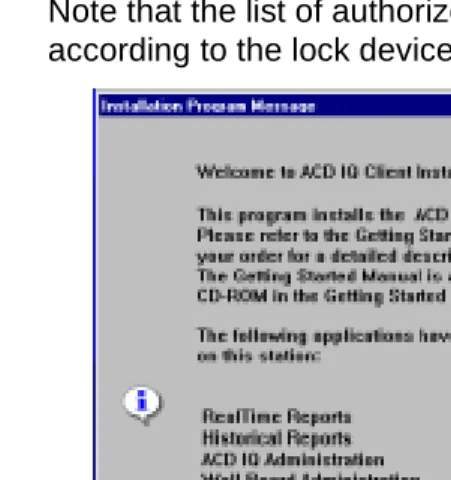
The installation program automatically identifies the type of installation to be performed (from the hardlock key).
Note that the list of authorized client applications according to the lock device, is displayed.
Figure 2-12: The Welcom Screen
6. Click OK to continue, or Cancel to exit the installation program.
7. The installation program displays the prompt shown in Figure 2-13:
8. By default, ACD IQ client is installed on drive C: under the directory C:\ACDIQ.
To install ACD IQ on drive C:
• Select Use the default drive.
To install ACD IQ on a different drive:
• Select Change the drive and select the required drive from the list.
9. The current server and client IP addresses are dis-played, and you are prompted to confirm or change them as required, as shown in Figure 2-14.
Figure 2-14: Confirming IP Address
addresses, please ask the network administrator.
Figure 2-15: Changing the Client IP Address
Figure 2-16: Changing the Client Server IP Address
Figure 2-17: Changing the Server name
12.By default, the installation procedure installs the Sybase SQL Anywhere 5.5 Database Software in the directory C:\SQLANY50 (see Figure 2-9: Entering the SQL Directory). You may now change this directory (though it is not recommended).
13.After clicking OK the following message is displayed.
Figure 2-18: The Ready for Installation Message
NOTE
This message changes according to the installation procedure selected by the lock device.
a progress bar showing the percentage completed, is presented.
After the files have been copied, the following message is displayed:
Figure 2-19: The Modifying AUTOEXEC.BAT file message
15.If you click Yes, the installation process makes the nec-essary changes to the AUTOEXEC.BAT file and informs you of them. In addition, a backup copy of the original AUTOEXEC.BAT file is made under the name AUTOEXEC.BAK.
NOTE
If you have any problems you can restore the original AUTOEXEC.BAT file by overwriting the current AUTOEXEC.BAT file with AUTOEXEC.BAK.
Once the installation is completed, the following mes-sage is displayed:
16.Click OK. When you have finished, reboot the com-puter.
You are now ready to run ACD IQ.
2.4.3 After Installation
At the end of the installation process for a Network Client configuration, the following ACD IQ Program Group opens:
Figure 2-21: ACD IQ Program Group
At the end of the installation process for a Standalone con-figuration, the ACD IQ Program Group opens with two ad-ditional icons, for starting and stopping ACD IQ, as displayed below:
Figure 2-22: ACD IQ Program Group (Standalone)
The following four ACD IQ applications are located on the server and on each client station:
• Administration;
• Real-Time Monitoring; • Historical Reports;
NOTE
On the network client station, the Real-Time Monitoring application is copied to the Startup folder to enable it to run auto-matically. On the server, an icon is cop-ied to the Startup folder to enable you to start ACD IQ.
In order to load ACD IQ, shut down and turn off the server or standalone computer, wait a few seconds, and then turn it on again. The database server is loaded and the ACD IQ server starts up. For a first-time installation, initial database setup is required (see Sections 3.1-3.3 for details).
2.4.4
Installing Over an Existing
ACD IQ System
Section 3
GETTING STARTED
3.1
STARTING THE ACD IQ SYSTEM
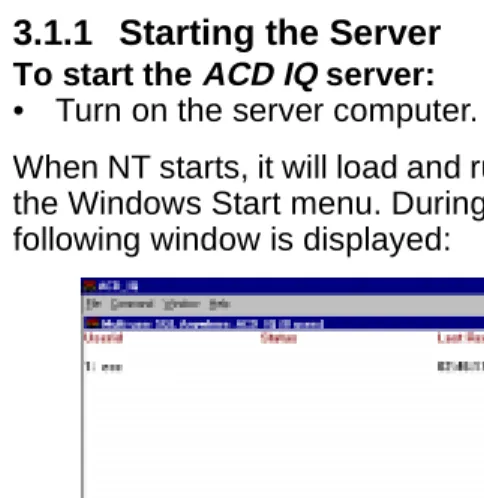
3.1.1 Starting the Server
To start the ACD IQ server:• Turn on the server computer.
When NT starts, it will load and run the ACD IQ Server, via the Windows Start menu. During the startup process, the following window is displayed:
Figure 3-1: Connecting to the Server
NOTE
3.1.2 Starting the Client
To start the ACD IQ client:1. Turn on the client computer. 2. Enter Windows for Win 3.11.
The Sybase SQL Anywhere 5.5 Client is automatically loaded, and tries to link to the ACD IQ server. After it suc-ceeds in linking to the server, Figure 3-2 is displayed.
Figure 3-2: Connected to the Server
If the client cannot connect to the server, an error message is displayed. For details about problem handling, refer to Section 4: Troubleshooting.
NOTE
The ACD IQ Program Group contains five icons:
To run an ACD IQ application:
• Double-click on the appropriate icon in the ACD IQ group.
NOTE
If this is a first installation, you must define initial parameters before running the client applications (see Section 3.3 Setting the Parameters for a First Time Installation).
The ACD IQ Login window is displayed. Before you can en-ter an ACD IQ application, you must first be assigned a unique user name and password by the system manager.
Figure 3-3: The ACD IQ Login Window Historical
Reports
Used to run the Historical Reports application.
ACD IQ Administration
Used to run the Administration application.
ACD IQ Help Used to run the ACD IQ on-line help system.
Real-Time Monitoring
Used to run the Real-Time Monitor-ing application.
Wall Board Administration
To log in to a selected application:
1. Enter you login name in the Login Name field. 2. Enter your password in the Password field. 3. Click OK.
If you type an incorrect user name or password, the fol-lowing error message is displayed and you will not be able to access the selected application.
Figure 3-4: The Login Error Message
4. Click OK to exit the dialog box and try again.
3.2
SHUTTING DOWN THE SYSTEM
3.2.1 Shutting Down the Server
To shut down the server:• Double-click on the Stop button in the ACD IQ Program Group.
The Server shuts down automatically.
3.2.2 Shutting Down a Client Station
To shut down a client station:1. Exit any open applications by pressing <Alt+F4>. 2. Exit Windows by pressing <Alt+F4> (for Windows 3.11
3.3
SETTING THE PARAMETERS
FOR A FIRST TIME INSTALLATION
After installing ACD IQ for the first time, in order to be able to run the system, a number of initial parameters must be defined in the ACD IQ Administration.
To define the initial parameters for a first time installa-tion:
1. Access the ACD IQ Administration application by dou-ble-clicking the Administration icon in the Program Group.
2. In the ACD IQ Login window that opens (see Figure 3-3: The ACD IQ Login Window), enter the following login name and password:
Login Name: ea Password: e1996
NOTE
This is the login name and password of a supervisor with full rights to access and edit all the ACD IQ parameters. The administrator of the system is asked to setup one more supervisor with similar privileges for regular work and to avoid the use of EA which should be saved for backup and technical maintenance.
After entering the password, the initial Administration screen is displayed.
select the Options option (see Figure 3-5).
Figure 3-5: Accessing the General Options Parameters
The General Options parameters are displayed in the screen.
Figure 3-6: General Options Parameters
4. Set the parameters according to your requirements, or leave the default values, as displayed. (For detailed information, refer to the online help system.) When you have finished, click the Update button.
5. Next, you can (optionally) specify the working/non-working days in the system. This information is neces-sary for calculating the daily average for historical reports by intervals, that span more than one day. To do this, select the Working Days option from the General menu (see Figure 3-5), and specify the working/non-working days as described in the online help system. 6. The next step is to define agent groups and their
Entities menu (see Figure 3-7).
Figure 3-7: Accessing the Groups Parameters
7. From the Group menu item that appears in the menu bar, select the Add option (see Figure 3-8).
The Groups General Parameters are displayed in the screen.
Figure 3-8: Add Group General Parameters
8. Click the following push buttons and define the parame-ters for each option, as specified in the online help sys-tem:
• General Params
• Thresholds (optional but recommended) • Group Agents
10.Shutdown the server by selecting the Shutdown option from the Tools menu (see Figure 3-9).
Figure 3-9: Tools Menu
3.4
ACD IQ CLIENT APPLICATIONS
The ACD IQ system comprises four applications; each as a separate entity and running independently of the other ap-plications. This section provides a brief description of each application (with sample screens), and describes various basic tasks that can be performed from each application.
3.4.1 The Administration Application
The ACD IQ Administration enables authorized supervisors to define system entities and modify them. The system con-figuration determined using this application, defines the in-formation that will be available for Historical and Real-Time reports.
Administration Application Operations
This section describes how to perform the following basic operations in the ACD IQ Administration:
1. Creating a new agent group.
2. Defining the parameters for the new group. 3. Adding agents to the newly created agent group.
Creating a New Agent Group To create a new agent group:
Window) to access the application and enter your login name and password in the Login window that opens. The Administration application main screen opens. 2. From the Entities menu, select the Groups option. 3. From the Group menu item that displays, select the Add
option.
4. A message is displayed informing you that the group will be seen only after restarting ACD IQ.
5. Click OK.
A new group is added to the list of groups displayed on the left side of the Administration screen, and its default param-eters are displayed on the right side of the screen.
Figure 3-10 below shows the General Parameters Group screen from the ACD IQ Administration.
Defining the Parameters
To define parameters for the new group:
• Fill in the General Parameters fields as displayed in the screen above (Figure 3-10), according to the following fields descriptions:
Once you have finished defining the parameters:
• Click Update to save them.
Adding Agents to the New Group
To add agents to the newly created agent group:
1. From the toolbar in the Administration application main screen, click the Groups icon.
Field Description
Name The name of the selected group.
Number The dial number of the group.
Target ASA Target Average Speed of Answer. The amount of time (in seconds) that the call should be answered, from the time it is received.
Max ACD Talk Time
The maximum amount of time (in seconds) suggested for a call on the line. Calls that exceed this time period are indicated in sta-tistical reports.
Interval Time Determines the time period that will be moni-tored in the real-time reports for the group. Setting this field to 10 min., for example, will cause the real-time report for that group to show statistical information relevant for the last 10 minutes.
Queue Number
A number used in the PCP program as the group number.
Service Time Intervals
Time periods that serve as start points for
2. From the list of groups at the left of the screen, select the newly created group.
3. Click the Group Agents push button.
4. From the Groups Agent Parameters screen that is dis-played, click Insert.
The following screen is displayed for adding a new group agent.
Figure 3-11: Adding a New Group Agent Screen
5. Fill in the required agent details in the appropriate fields and click Update to register the changes in the data-base.
The newly defined agent is added to the agent group.
NOTE
3.4.2 The Real-Time Monitoring
Application
The Real-Time Monitoring application allows you to obtain on-line statistical and graphic information concerning differ-ent Call Cdiffer-enter activities. The information can be displayed in many different table and graphic formats, providing you with a clear picture of what is actually going on in the cen-ter.
Real-Time Monitoring Operations
This section describes how to create the following two types of real-time windows in the Real-Time Monitoring application:
• Group Status Window, displaying the current activity
of each agent in a selected group, and for how long the agent has been engaged in that activity.
• Call Distribution Graph, displaying graphical pie chart
information about one group, such as the number of answered calls, number of abandoned calls, etc.
To create the Group Agent Status Window:
1. Double click on the Real-Time Monitoring icon in the ACD IQ Program Group (see Figure 3-3: The ACD IQ Login Window), to access the application and enter your login name and password in the Login window that opens.
The Real-Time Monitoring main screen opens.
2. From the File menu, select the New option to create a new real-time window.
4. In the New Group dialog box, double-click on the telem-etry group to obtain information on this group.
Information on the agents in this group is displayed in the window, as shown in the example in Figure 3-12.
Figure 3-12: Real-Time Group Agents Status Window NOTE
Information displayed in the screen is constantly updated, according to activity in the Call Center.
5. Save the report using the Save As option from the File menu and assign it a name.
To create the Call Distribution Graph window
1. From the File menu, select the New option to create a new real-time window.
2. In the New dialog box, double-click on the Call Distribu-tion Graphs template, or select the template and click OK.
4. Information on the calls activity in this group is dis-played in a window, as shown in the example in Figure 3-13 below.
Figure 3-13: The Real-Time Call Distribution Graph Window
5. After the window has been created with the information you requested, you can change the group presented in the report by selecting the Change option from the Con-tents menu.
6. For information on a specific section of a pie chart, dou-ble-click on the desired section.
7. To add/remove/change graphic entities in the graph, use the graphic toolbar.
8. Save the report using the Save As option from the File menu.
3.4.3 The Historical Reports Application
The Historical Reports application allows you to view histor-ical statisthistor-ical information for analythistor-ical purposes. The ap-plication contains several factory report structures that can be filled out and generated. In addition, it also enables you to define your own report structures.
Historical Reports Operations
applica-tion, and how to customize them according to your require-ments.
• The Agent Performance Report. This report is based
on one of the factory templates provided with ACD IQ. Using this report, you can analyze the performance of a specific agent over a specified period.
• The Group by Date Report. You can produce this
report by basing it on an existing template and adding columns as required. Using this report you can analyze the performance of an entire group over a specified period.
To create the Agent Performance Report:
1. Double click on the Historical Reports icon in the ACD IQ Program Group (see Figure 3-3: The ACD IQ Login Window) to access the application and enter your login name and password in the Login window that opens. The Historical Reports main screen opens.
2. From the File menu, select the Open option. A list of factory templates is displayed.
3. From the list, select the first Agent Performance Report (RA1.1) and click OK. The Agent Performance Report Window is opened on the screen.
4. As you can see, the only parameter that is defined is the Requested by: parameter. You can now define the remaining parameters for the report.
NOTE
5. Select the Parameters option from the Report menu, or click the right mouse button to the right of a parameter, and select the Parameters option. Fill in the parameters as shown in Figure 3-14.
Figure 3-14: Parameters Dialog Box
6. To select/define a value for a parameter, click on the parameter field and enter the value, as required. 7. When you have finished, click OK. The report template
should now look as shown in Figure 3-15 below.
8. Save the report under the name Agent-11 using the Save as option in the File menu.
You are now ready to generate the report and see the result on the screen.
To generate the Agent Performance Report:
1. Click the Generate button or select the Generate option from the Report menu.
2. After a few seconds, the generated report is presented in a new window on the screen, as displayed in Figure 3-16 below. (For a better view, maximize the window.)
Figure 3-16: The Generated Agent Performance Report
Note that the report displays the performance of agent Agent s2 between the hours specified (05:00 pm - 07:00 pm). The report contains one line for each interval period (every 15 minutes).
3. Go to the end of the report using the scroll bars. At the end of the report, you will see the sum total of the data presented in the report.
5. You may want to experiment by returning to the report template and scheduling the report for printing at a later time, using the Schedule option. For more information, refer to the ACD IQ context sensitive on-line help.
To create the Group by Date Report:
1. From the File menu, select the New option. A list of templates is displayed.
2. From the list, select the Group by Date template (1.2) and click OK.
The Group by Date Window is displayed.
Figure 3-17: Group By Date Window
As you can see, this template currently contains only one column - Date. In order to produce our report we will customize this template by adding columns to provide us with more information on the group performance. 3. Click the right mouse button to the right of the current
column in the report, and select the Insert Column option.
5. Next, fill in the report parameters with relevant dates and times. Note that in order to produce a meaningful report, the system must have been running for the specified period of time. An example of dates and times is displayed below:
6. For this data, your report should now look as follows:
Figure 3-18: The Group by Date Report Template
Column Name Description
Total Calls Total number of calls.
Total Calls Abndn. Total number of abandoned ACD calls.
ACD Calls answered Number of ACD calls answered.
Agent RPH Average number of calls per
hour answered by the group. Cmltv. Wait Time on Que
(hh:mm:ss)
Accumulated waiting time in queue.
Date From: Now - 4 (i.e., Current date - 4 days) Date To: Now (i.e., Current Date)
Time From: 08:00 am
Time To: 08:00 pm
Group Name: Service
Group No: 30
7. You may save the template, if you want, under a new name, using the Save As option.
8. Finally, generate the report and view the results.
NOTE
Generated reports are shown on a new static window which reflects the results of the required report. Any change to the layout of the template or the parameters of the report requires regeneration of the report and are reflected on a new static windows.
Figure 3-19: The Group by Date Generated Report
3.4.4 The Wall Board Administration
Wall Board Administration Operations
This section describes how to define your physical Wall Board, how to create your message library and how to build your messages scenario for your Wall Board.
To define a new physical Wall Board
1. Double click on the Wall Board Administration icon in the ACD IQ Program Group (see Figure 3-3: The ACD IQ Login Window) to access the application and enter your login name and password in the Login window that opens.
2. Click on the Wall Board speed button.
3. Click the New button. Give your Wall Board a name and address. Select the Wall Board type and choose the communication parameters.
4. Remember to click the Save button to save the new Wall Board.
To create a new message in the Message Library:
1. Click on the Message Editor speed button.
The Messages Editor screen of the Wall Board Admin-istration opens, as displayed below.
Figure 3-20: The Wall Board Messages Editor Screen
Define the default group and use the editor to edit your message.
3. Click the Param button to insert a parameter for the message.
The following dialog box opens.
Figure 3-21: Parameters Dialog Box
4. Select the required parameter, define its length (optional). Click the OK button to accept the new parameter. Click the Cancel button to cancel the opera-tion.
5. In the Message Editor screen, remember to click the Update button to save the new message.
To build a scenario for the physical Wall Board:
The following dialog box opens.
Figure 3-22: Add Welcome Message to Scenario Dialog Box
2. Define the time, in seconds, this message should stay on the Wall Board. Click OK to actually add the mes-sage to the scenario, or Cancel to cancel this operation. 3. You may use the upper/lower arrow buttons to re
arrange the messages order in the scenario.
4. Click the Run button at the left side of the screen to accept your new scenario.
3.4.5 Summary
A
Section 4
TROUBLESHOOTING
This chapter contains a list of problems that might occur during the course of the installation process. For each prob-lem, an explanation and a solution to the problem are pre-sented.
In the list that follows, the following key is used:
P = Problem E = Explanation S = Solution
P: The ACD IQ Server does not come up (i.e., the logo is not shown).
E: After installation, the ACD IQ server machine needs to be rebooted for all changes to take effect.
The security plug should be connected to the parallel port (LPT1)
After a power fail, there is an inconsistency on the data-base updates.
S: Shutdown and reboot the server.
Check that the security plug is connected to the parallel port.
Change the name of the file \ACDIQ\DB\ECC.LOG and restart the ACDIQ Server. If the problem persists call technical support.
P: Theclient applications refuse to run in a network environment.
(3) The IP addresses or workstations names are not set correctly.
(4) The server has been restarted.
S: (1) Check that the server is up and running.
(2) Check that the client station can connect with the server; or other workstations on the network use the PING facility to test basic IP functionality (by number and name).
(3) Check that the addresses and the workstations names set for the client and server are correct (the addresses which work correctly for PING). (4) Exit and restart Windows after the server has
come up.
P: After installation, the client applications refuse to give the user access (i.e., logins fail).
E: If you have an empty database, there are no authorized users.
S: Run the ACD IQ administration application, login as user 'EA' with password 'E1996'. Create new supervisors who can then login and run the applications for which they have access rights. See Section 3.3.
P: There seems to be no communication with the PBX.
E: The communications parameters are not defined prop-erly.
Physical connections problems.
The phone station wired to the ACD IQ server is not con-nected or not properly defined on the PBX.
S: Make sure that:
Appendix A
PC for project ACD I.Q.
Specification Requirements
1. Processor: 586 (PENTIUM), 200MHz minimum 2. RAM : 64 Mb Min
3. AC input:
* 220 / 110 Vac, 50/60 Hz . 4. IDE Hard Disk:
* Capacity - 2 Gb minimum * Faster than 10 msec
* MTBF - more than 45000 hours. 5. CACHE Memory : 256 kb minimum. 6. Floppy Disk Driver : 3.5 ”, 1.44 Mb. 7. CD-ROM drive
8. Slots:
* PSI - 3 slots minimum
* ISA - full 4 slots.
9. Power Supply : 200 W minimum.
10. Screen card: MACH 64 with 2Mb memory or equiva-lent.
11. Screen: SVGA 15 “ (17” Recommended) 12. Ports :
13. Keyboard : WIN 95 compatible English 14. Mouse : Bus Mouse.
15. Modem card: 33.6 kb/s, Hayes compatible. Communi-cation port: COM3 with interrupt #5.
16. Real Time Clock with battery back-up.
17. Networking card: 3COM59X-TPO,( 3COM900 in the future).
18. Operating systems : WINDOW NT 4.0 workstation with documentation and certificates installed in the PC.
NOTE
For more than 10 net connections, WIN-DOWS NT Server is required !
19. The PC shall be approved : CE FCC UL. 20. NT supported:
a.ANTIVIRUS software installed on the PC
b.PC ANYWHERE software package for win NT/95/ 3.1 by Symantec Corporation Vers.8.0 or higher. 21. Any power down (including momentary) shall cause a