Efficient Constant Round Multi-Party Computation
Combining BMR and SPDZ
∗Yehuda Lindell† Benny Pinkas† Nigel P. Smart‡ Avishay Yanai†
Abstract
Recently, there has been huge progress in the field of concretely efficient secure computation, even while providing security in the presence of malicious adversaries. This is especially the case in the two-party setting, where constant-round protocols exist that remain fast even over slow networks. However, in the multi-party setting, all concretely efficient fully-secure protocols, such as SPDZ, require many rounds of communication.
In this paper, we present a constant-round multiparty secure computation protocol that is fully-secure in the presence of malicious adversaries and for any number of corrupted parties. Our construction is based on the constant-round protocol of Beaver et al. (the BMR protocol), and is the first version of that protocol that isconcretely efficient for the dishonest majority case. Our protocol includes an online phase that is extremely fast and mainly consists of each party locally evaluating a garbled circuit. For the offline phase we present both a generic construction (using any underlying MPC protocol), and a highly efficient instantiation based on the SPDZ protocol. Our estimates show the protocol to be considerably more efficient than previous fully-secure multi-party protocols.
1
Introduction
1.1 Background and Prior Work
honest majority (or a 2/3 majority) is assumed, security can even be obtained information theo-retically [5,6, 30]. In this paper, we focus on the problem of obtaining security in the presence of malicious adversaries, and a dishonest majority.
Recently, there has been much interest in the problem of concretely efficient secure MPC, where “concretely efficient” refers to protocols that are sufficiently efficient to be implemented in practice (in particular, these protocols should not, say, use generic ZK proofs that operate on the circuit representation of these primitives). In the last few years there has been tremendous progress on this problem, and there now exist extremely fast protocols that can be used in practice; see [23,24,26,22,12] for just a few examples. In general, there are two approaches that have been followed; the first uses Yao’s garbled circuits [32] and the second utilizes interaction for every gate like the GMW protocol [14].
There are extremely efficient variants of Yao’s protocol for the two party case that are secure against malicious adversaries (e.g., [23, 24]). These protocols run in a constant number of rounds and therefore remain fast over high latency networks. The BMR protocol [1, 31] is a variant of Yao’s protocol that runs in a multi-party setting with more than two parties. This protocol works by the parties jointly constructing a garbled circuit (possibly in an offline phase), and then later computing it (possibly in an online phase). However, in the case of malicious adversaries, the original BMR protocol suffers from two main drawbacks:
• The protocol uses circuit-based zero-knowledge proofs to ensure that the parties input correct values obtained from the pseudorandom generator in the protocol. This requires a very large proof (of a circuit computing a pseduorandom generator) for every gate of the circuit. Thus, the protocol serves as a feasbility result for achieving constant-round MPC, but cannot be run in practice.
• The original BMR protocol only guarantees security for malicious adversaries if at most a minorityof the parties are corrupt. This is due to the fact that constant-round protocols for multiparty commitment, coin-tossing and zero-knowledge were not known at the time for the setting of dishonest majority. The existence of constant-round protocols for multiparty secure computation in the presence of a dishonest majority was proven later in [18, 27]. However, these too are feasibility results and are not concretely efficient.
1.2 Our Contribution
In this paper, we provide the firstconcretely-efficient constant-roundprotocol for the general mul-tiparty case, with security in the presence of malicious adversaries and a dishonest majority. Our protocol has 12 communication rounds, of which only 3 rounds are in the online phase. This makes it much more efficient than prior protocols [26, 12] for deep circuits and/or slow networks, since prior works all have a number of rounds that is (at least) the depth of the circuit being computed. The basic idea behind the construction is to use an efficient (either constant or non-constant round) protocol, with security for malicious adversaries, to compute the gate tables of the BMR garbled circuit (and since the computation of these tables is of constant depth, this step is constant round). Our main conceptual contribution, resulting in a great performance improvement, is to show that it is not necessary for the parties to prove (expensive) zero-knowledge proofs that they used the correct pseudorandom generator values in the offline circuit generation phase. Rather, validation of the correctness is an immediate byproduct of the online computation phase, and therefore does not add any overhead to the computation. Although our basic generic protocol can be instantiated with any MPC protocol (either constant or non-constant round), we provide an optimized version that utilizes specific features of the SPDZ protocol [12].
In our general construction, the new constant-round protocol consists of two phases. In the first (offline) phase, the parties securely computerandom shares of the BMR garbled circuit. If this is done naively, then the result is highly inefficient since part of the computation involves computing a pseudorandom generator or a pseudorandom function multiple times for every gate. By modifying the original BMR garbled circuit, we show that it is possible to actually compute the circuit very efficiently. Specifically, each partylocallycomputes the pseudorandom function as needed for every gate1 and uses the results as input to the secure computation. Our proof of security shows that if a party cheats and inputs incorrect values then no harm is done, since this only causes the honest parties to abort (which is inevitable in the dishonest majority anyway). Next, in the online phase, all that the parties need to do is reconstruct the single garbled circuit, exchange garbled values on the input wires and evaluate compute the garbled circuit. The online phase is therefore very fast.
In our concrete instantiation of the protocol using SPDZ [12], there are actually three separate phases, with each being faster than the previous. The first two phases can be run offline, and the last phase is run online after the inputs become known.
• The first (slow) phase depends only on an upper bound on the number of wires and the number of gates in the function to be evaluated. This phase uses Somewhat Homomorphic Encryption (SHE) and is equivalent to the offline phase of the SPDZ protocol.
• The second phase depends on the function to be evaluated but not on the function inputs; in our proposed instantiation this mainly involves information theoretic primitives and is equivalent to the online phase of the SPDZ protocol.
• In the third phase the parties provide their inputs and evaluate the function; this phase just involves exchanging shares of the circuit and garbled values on the input wires and locally evaluate the BMR garbled circuit.
preparing the BMR garbled circuit is not much more than the cost of using SPDZ itself to compute the functionality directly. However, the key advantage that we gain is that our online time is extraordinarily fast, requiring only two rounds and a local computation of a single garbled circuit. This is faster than all other existing circuit-based multi-party protocols.
Finite field optimization of BMR. In order to efficiently compute the BMR garbled circuit, we define the garbling and evaluation operations over a finite field. A similar technique of using finite fields in the BMR protocol was introduced in [2] in the case of semi-honest security with an honest majority. In contrast to [2], our utilization of finite fields is carried out via vectors of field elements, and uses the underlying arithmetic of the field as opposed to using very large finite fields to simulate integer arithmetic. This makes our modification in this respect more efficient.
Subsequent Work. Following our work, there has been renewed interest in the BMR protocol. First and foremost, the works of [25,16] build directly on this work and show how to construct the BMR garbled circuit more efficiently. In addition, [3] considered the semi-honest setting, and [21] apply an optimized version of our construction to efficient RAM-based MPC. The fact that constant-round BMR protocol outperform secret-sharing based protocols for not-shallow circuits and slow (Internet-like) networks has been demonstrated in [3,4,21].
1.3 Paper Structure
In Section 2 we give a detailed description of the BMR protocol. In Section 3 we present our general protocol, that can utilize any MPC protocol for arithmetic circuits as a subprocedure. Then, in Section 4, we describe our specific BMR protocol that uses SPDZ [12] as the underlying MPC protocol, and we analyze its complexity. We utilize specific properties of SPDZ for further optimizations, in order to obtain an even more efficient evaluation. Finally, we provide a full proof of our construction in Section 5.
2
Background – the BMR Protocol [
1
]
We outline the basis of our protocol, which is the protocol of Beaver, Micali and Rogaway against a semi-honest adversary2. The protocol is comprised of anoffline-phaseand anonline-phase. In the
offline-phasethe garbled circuit is constructed by the parties, while in the online-phasea matching set of garbled inputs is exchanged between the parties and each party evaluates it locally.
We now describe the main elements of the BMR protocol. Let κ denote the computational security parameter, n denote the number of parties, and let [n] = {1, . . . , n}. The wires in the circuit that computes the function f are indexed 0, . . . , W −1. The protocol is based on the following key components:
Seeds and superseeds. Two random seeds are associated with each wire in the circuit by each party. We denote the 0-seed and 1-seed that are chosen by partyPi (i∈[n]) for wirewassiw,0 and
siw,1 such thatsiw,j ∈ {0,1}κ. During the garbling process the parties produce twosuperseeds for
2Their original work also offers a version against a malicious adversary, however, it requires an honest majority
each wire, where the 0-superseed and 1-superseed for wire w are a simple concatenation of the 0-seeds and 1-0-seeds chosen by all the parties, namely,Sw,0 =s1w,0k · · · ksnw,0 and Sw,1=s1w,1k · · · ksnw,1 wherek denotes concatenation. DenoteL=|Sw,j|=n·κ.
Garbling wire values. For each gate g that calculates the function fg (where fg : {0,1} ×
{0,1} → {0,1}), the garbled gate of g is computed such that the superseeds associated with the output wire are encrypted (via a simple XOR) using the superseeds associated with the input wires, according to the truth table offg. Specifically, a superseedSw,0=s1w,0k · · · ksnw,0 is used to encrypt a value M of length L by computing MLn
i=1G(siw,0), where G is a pseudo-random generator stretching a seed of lengthκto an output of length L. This means thatevery one of the seeds that make up the superseed must be known in order to learn the mask and decrypt.
Masking values. Using random seeds instead of the original 0/1 values does not hide the original value if it is known that the first seed corresponds to 0 and the second seed to 1. Therefore, an unknown random masking bit, denoted by λw, is assigned to each wire w independently. These
masking bits remain unknown to the parties during the entire protocol, thereby preventing them from knowing thereal values ρwthat actually pass through the wires. The values that the partiesdo
know are called theexternal values, denoted Λw. An external value is defined to be the exclusive-or
of the real value and the masking value; i.e., Λw =ρw⊕λw. When evaluating the garbled circuit
the parties only see the external values of the wires, which are random bits that reveal nothing about the real values, unless they know the masking values. We remark that each partyPi is given
the masking value associated with its input, hence, it can compute the external value itself (based on its actual input) and can send it to all other parties.
BMR garbled gates and circuit. We can now define the BMR garbled circuit, which consists of the set of garbled gates, where a garbled gate is defined via a functionality that maps inputs to outputs. Let g be a gate with input wires a, b and output wire c. Each party Pi inputs
sia,0, sia,1, sb,i0, sib,1, sic,0, sc,i1. Thus, the appropriate superseeds areSa,0, Sa,1, Sb,0, Sb,1, Sc,0, Sc,1, where each superseed is given bySα,β =s1α,βk · · · ksnα,β. In addition,Pialso inputs the output of a
pseudo-random generator G applied to each of its seeds, and its share of the masking bits, i.e. λia, λib, λic
(where λw =Lni=1λiw).
Functionality 1 (garble-gate-BMR).
Letκdenote the security parameter, and letG:{0,1}κ→ {0,1}2nκ be a pseudo-random
gener-ator. Denote the firstL=n·κbits of the output ofGbyG1, and the lastnκbits of the output
ofGbyG2.
The garbling of gate g computingfg :{0,1} × {0,1} → {0,1} with inputs wiresa, band output
wirec is defined as follows:
Inputs: For each gate the inputs are given by
• Seeds: PartyPi inputs uniformsix,b∈ {0,1}κforx∈ {a, b, c}andb∈ {0,1}.
• Stretched seeds: Party Pi inputs the L-bit strings ˜Υix,b and Υ i
x,b for x∈ {a, b, c} and
b∈ {0,1}. (IfPiis honest then ˜Υix,b=G1(sx,bi ) and Υix,b=G2(six,b); i.e. ˜Υix,band Υix,bare
the output of the pseudorandom generatorGon the seedsi x,b).
• Masking bits. PartyPi inputs a uniformλix∈ {0,1}forx∈ {a, b, c}.
Outputs: The functionality first computes λx = L n i=1λ
i
x for x ∈ {a, b, c}. Then
set Sc,A = (fg(λa, λb) =λc?Sc,0:Sc,1), Sc,B = fg(λa,λ¯b) =λc?Sc,0:Sc,1, Sc,C =
fg( ¯λa, λb) =λc?Sc,0:Sc,1
, Sc,D = fg( ¯λa,λ¯b) =λc?Sc,0:Sc,1
, The garbled gate of g is the following four ciphertextsAg, Bg, Cg, Dg (in this order that is determined by the external values):
Ag = Υ˜1a,0⊕ · · · ⊕Υ˜
n a,0⊕Υ˜
1
b,0⊕ · · · ⊕Υ˜
n
b,0⊕Sc,A
Bg = Υ1a,0⊕ · · · ⊕Υ
n a,0⊕Υ˜
1
b,1⊕ · · · ⊕Υ˜
n
b,1⊕Sc,B
Cg = Υ˜1a,1⊕ · · · ⊕Υ˜
n a,1⊕Υ
1
b,0⊕ · · · ⊕Υ
n
b,0⊕Sc,C
Dg = Υ1a,1⊕ · · · ⊕Υ
n a,1⊕Υ
1
b,1)⊕ · · · ⊕Υ
n
b,1⊕Sc,D
The BMR Online Phase. In the online-phase the parties only have to obtain one superseed for every circuit-input wire, and then every party can evaluate the circuit on its own, without interaction with the rest of the parties. Formally, Protocol1 realize the online-phase.
Protocol 1 (Protocol BMR-online-phase). Step 1 – send values:
1. Every partyPi broadcasts the external values on the wires associated with its input.
At the end of this step the parties know the external value Λwfor every circuit-input
wirew. (Recall thatPi knowsλw and so can compute Λw based on its input.)
2. Every partyPi broadcasts one seed for each circuit-input wire, namely, the Λw-seed.
At the end of this step the parties know the Λw-superseed for every circuit-input wire.
Step 1 – evaluate circuit: The parties evaluate the circuit from bottom up, such that to obtain the superseed of an output wire of the gate, useAg if the external values ofg’s input wires
are Λa,Λb = (0,0), use Bg if Λa,Λb= (0,1),Cg if Λa,Λb= (1,0) and Dg if Λa,Λb = (1,1)
Correctness. We explain now why the conditions for masking Sc,0 and Sc,1 are correct. The external values Λa,Λb indicate to the parties which ciphertext to decrypt. Specifically, the parties
decrypt Ag if Λa= Λb = 0, they decrypt Bg if Λa= 0 and Λb = 1, they decrypt Cg if Λa= 1 and
Λb = 0, and they decrypt Dg if Λa= Λb = 1.
We need to show that given Sa,Λa and Sb,Λb, the parties obtain Sc,Λc. Consider the case that
Λa = Λb = 0 (note that Λa= 0 means that λa=ρa, and Λa= 1 means that λa 6=ρa, where ρa is
the real value). Sinceρa=λa and ρb =λb we have that fg(λa, λb) =fg(ρa, ρb). If fg(λa, λb) =λc
then by definition fg(ρa, ρb) = ρc, and so we have λc = ρc and thus Λc = 0. Thus, the parties
obtain Sc,0 = Sc,Λc. In contrast, if fg(λa, λb) 6= λc then by definition fg(ρa, ρb) 6= ρc, and so we
haveλc= ¯ρc and thus Λc= 1. A similar analysis show that the correct values are encrypted for all
other combinations of Λa,Λb.
Broadcast. As described in Protocol1, in theonline-phasethe parties are instructed to broadcast one key per input wire. In the semi-honest setting broadcasting a value simply takes one commu-nication round in which the sender sends its value to all other parties3. However, in the malicious setting a corrupted sender may send the valuevto one party and a different valuev0 6=vto another party. In the setting of t < n/3 corrupted parties fully secure broadcast (without abort) can be achieved in an expected constant number of rounds [13] (or deterministically int rounds [28]). In the setting of t ≥ n/3 corrupted parties, and in particular with no honest majority at all, fully secure broadcast (without abort) can only be achieved using a public-key infrastructure and witht
rounds of communication. However, we donot actually need a fully secure broadcast, since we allow an adversary to cause some parties to abort. Thus, we can use a simple two-round echo-broadcast protocol; this has been shown to be sufficient for secure computation with abort [15] (and even UC secure). In more detail, the echo-broadcast works by having the sender send its message v to all parties P1, . . . , Pn in the first round, and then every party Pi sends (echoes) the value that it
received in the first round to all other parties. If any party received two different values, then it aborts. Otherwise, it outputs the unique value that it saw. It is not difficult to show that if the dealer is honest, then all honest parties either output the dealer’s messagev or abort (but no other value can be output). Furthermore, if the dealer is dishonest, then there is a unique value v such that every honest party either outputs v or aborts. See [15] for more details. We therefore write our protocol assuming a broadcast channel, and utilize the above protocol to achieve broadcast in the point-to-point setting. As a result, our protocol has a constant number of rounds even in the point-to-point model.
3
The General Protocol
3.1 A Modified BMR Garbling
any number of corrupted parties. Consequently, we naturally replace the seeds six,b, which are bit-strings input to a pseudorandom generator, that the parties input with keys kix,b, which are field elements input to a pseudorandom function.
Second, we observe that the external values of wires4 do not need to be explicitly encoded, since each party can learn them by looking at its own “part” of the garbled value. In the original BMR garbling, each superseed containsnseeds provided by the parties. Thus, if a party’s zero-seed is in the decrypted superseed then it knows that the external value (denoted by Λ) is zero, and otherwise it knows that it is one.
Naively, it seems that independently computing each gate securely in the offline phase is insuf-ficient, since the corrupted parties might use inconsistent inputs for the computations of different gates. For example, if the output wire of gate g is an input to gate g0, the input provided for the computation of the table of g might not agree with the inputs used for the computation of the table of g0. It therefore seems that the offline computation must verify the consistency of the computations of different gates. This type of verification would greatly increase the cost since the evaluation of the pseudorandom functions (or pseudorandom generator in the original BMR) used in computing the tables needs to be checked inside the secure computation. This would mean that the pseudorandom function is not treated as a black box, and the circuit for the offline phase would be huge (as it would include multiple copies of a subcircuit for computing pseudorandom function computations for every wire). Instead, we prove that this type of corrupt behavior can only result in an abort in the online phase, which would not affect the security of the protocol. This observation enables us to compute each gate independently and model the pseudorandom function used in the computation as a black box, thus simplifying the protocol and optimizing its performance.
We also encrypt garbled values as vectors; this enables us to use a finite field that can encode values from {0,1}κ (for each vector coordinate), rather than a much larger finite field that can
encode all of {0,1}L. Due to this, the parties choosekeys (for a pseudorandom function) rather
than seeds for a pseudorandom generator. The keys that Pi chooses for wire w are denoted kiw,0 and kw,i 1, which will be elements in a finite field Fp such that 2κ < p <2κ+1. In fact, we pick p
to be the smallest prime number larger than 2κ, and set p= 2κ+α, where (by the prime number theorem) we expect α ≈κ. We shall denote the pseudorandom function by Fk(x), where the key
and output will be interpreted as elements of Fp in much of our MPC protocol. In practice the
function Fk(x) we suggest will be implemented using CBC-MAC using a block cipher enc with
key and block size κ bits, asFk(x) = CBC-MACenc(k (mod 2κ), x). Note that the inputs x to our pseudorandom function will all be of the same length and so using naive CBC-MAC will be secure. We interpret the κ-bit output of Fk(x) as an element in Fp where p = 2κ +α. Note that
a mapping which sends an element k ∈ Fp to a κ-bit key by computing k (mod 2κ) induces a distribution on the key space of the block cipher which has statistical distance from uniform of only
1 2
(2κ−α)·
1 2κ −
1
p
+α·
2
p −
1 2κ
≈ α
p ≈ κ
2κ.
The output of the function Fk(x) will also induce a distribution which is close to uniform on Fp.
4The external values (as denoted in [2]) are thesignals(as denoted in [1]) observable by the parties when evaluating the
In particular the statistical distance of the output inFp, for a block cipher with block sizeκ, from
uniform is given by
1 2
2κ·
1 2κ −
1
p
+α·
1
p −0
= α
p ≈ κ
2κ
(note that 1−2pκ = αp). The statistical difference is therefore negligible. In practice we setκ= 128, and use the AES cipher as the block cipher enc.
Functionality 2 (The SFE Functionality: FSFE).
The functionality is parameterized by a functionf(x1, . . . , xn) which is input as a binary circuit Cf.
The protocol consists of 3 externally exposed commandsInitialize,InputData, andOutputand one internal subroutineWait.
Initialize: On input (init, Cf) from all parties, the functionality activates and storesCf.
Wait: This waits on the adversary to return aGO/NO-GO decision. If the adversary returnsNO-GO then the functionality aborts.
InputData: On input (input, Pi, xi) fromPiand (input, Pi,?) from all other parties, the functionality
stores (Pi, xi). Upon having (Pi, xi) for alli∈[n] the functionality callsWait.
Output: On input (output) from all honest parties the functionality computes y=f(x1, . . . , xn) and
outputsy to the adversary. The functionality then callsWait. Only if Waitdoes not abort it outputsyto all parties.
In what follows we assume that the FMPC functionality maintains a data structure in which it stores its internal values, so that the parties may request to perform operations (i.e. Input, Output, Add, Multiply) over the entries of the data structure. We use the notation [val] to represent the key used by the functionality to store value val. In addition, we use the arithmetic shorthands [z] = [x] + [y] and [z] = [x]·[y] to represent the result of calling theAddandMultiply
commands over the inputsx, yand outputz. That is, after calling [z] = [x]+[y] (resp. [z] = [x]·[y]) the key [z] is associated with the valuex+y (resp. x·y).
In the Output command of FMPC (Functionality 3), i = 0 means that the value indexed by
varid is output to all parties andi6= 0 means that it is output to partyPi only. In both cases the
adversary has the power to decide if an honest party receives the output value or not (where in the latter case, it aborts). Furthermore, wheni= 0, the adversary has the ability to inspect that value before deciding whether to abort.5
Functionality 3 (The Generic Reactive MPC Functionality: FMPC).
The functionality consists of five externally exposed commandsInitialize,InputData,Add,Multiply, andOutput, and one internal subroutineWait.
Initialize: On input (init, p) from all parties, the functionality activates and storesp(otherwise, i.e. if the parties do not agree onp, the functionality halts). All additions and multiplications below will be modp.
Wait: This waits on the adversary to return aGO/NO-GO decision. If the adversary returnsNO-GO then the functionality aborts.
InputData: On input (input, Pi,varid, x) fromPi and (input, Pi,varid,?) from all other parties, with
varida fresh identifier, the functionality stores (varid, x). The functionality then callsWait.
Add: On command (add,varid1,varid2,varid3) from all parties (ifvarid1,varid2are present in memory
andvarid3 is not), the functionality retrieves (varid1, x), (varid2, y) and stores (varid3, x+ymod
p). The functionality then callsWait.
Multiply: On input (multiply,varid1,varid2,varid3) from all parties (if varid1,varid2 are present in
memory andvarid3is not), the functionality retrieves (varid1, x), (varid2, y) and stores (varid3, x·
ymodp). The functionality then callsWait.
Output: On input (output,varid, i) from all honest parties (ifvaridis present in memory), the function-ality retrieves (varid, x) and outputs either (varid, x) in the case ofi6= 0 or (varid) ifi= 0 to the adversary. The functionality then callsWait, and only ifWaitdoes not abort then it outputsx
to all parties ifi= 0, or it outputsxonly to partyiifi6= 0.
3.2 The Offline Functionality: preprocessing-I and preprocessing-II
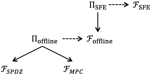
Our protocol, ΠSFE, is comprised of an offline-phase and an online-phase, where the offline-phase, which implements the functionality Foffline, is divided into two subphases: preprocessing-I and
preprocessing-II. To aid exposition we first present the functionality Foffline in Functionality 4. In
5Recall that we write our protocol assuming a broadcast channel. Thus, even though we write that in the output
Section4we present an efficient methodology to implementFofflinewhich uses the SPDZ protocol as the underlying MPC protocol for securely computing functionalityFMPC; while in AppendixAwe present a generic implementation of Foffline based on any underlying protocol ΠMPC implementing
FMPC.
In describing functionality Foffline we distinguish between attached wires and common wires: the attached wires are the circuit input-wires that are directly connected to the parties (i.e., these are inputs wires to the circuit). Thus, if every party has`inputs to the functionality f then there aren·`attached wires. The rest of the wires are considered ascommonwires, i.e. they are directly connected tonone of the parties.
Our preprocessing-I phase takes as input an upper bound W on the number of wires in the
circuit, and an upper bound G on the number of gates in the circuit. The upper bound Gis not strictly needed, but will be needed in any efficient instantiation based on the SPDZ protocol. In contrast, the preprocessing-II phase requires knowledge of the precise function f being computed, which we assume is encoded as a binary circuitCf.
In order to optimize the performance of preprocessing-IIphase, the secure computation does not evaluate the pseudorandom function F(), but rather has the parties computeF() and provide the results as an input to the protocol. Observe that corrupted parties may provide incorrect input values Fki
x,j() and thus the resulting garbled circuit may not actually be a valid BMR garbled
circuit. Nevertheless, we show that such behavior can only result in an abort. This is due to the fact that if a value is incorrect and honest parties see that their key (coordinate) is not present in the resulting vector then they will abort. In contrast, if their seed is present then they proceed and the incorrect value had no effect. Since the keys are secret, the adversary cannot give an incorrect value that will result in a correct different key, except with negligible probability. Likewise, a corrupted party cannot influence the masking values λ, and thus they are consistent throughout (when a given wire is input into multiple gates), ensuring correctness.
3.3 Securely Computing FSFE in the Foffline-Hybrid Model
In Protocol2we present our protocol ΠSFEfor securely computingFSFEin theFoffline-hybrid model. In this paper we prove the following:
Theorem 1 (Main Theorem). If F is a pseudorandom function, then ProtocolΠSFE securely
com-putes FSFE in the Foffline-hybrid model, in the presence of a static malicious adversary corrupting
Functionality 4 (The Offline Functionality –Foffline).
This functionality runs the same Initialize, Wait, InputData and Output commands as FMPC (Functionality 3). In addition, the functionality has two additional commands preprocessing-I and
preprocessing-II, as follows.
preprocessing-I: On input (preprocessing-I, W, G), for every wirew∈[1, . . . , W]:
• Choose and store a random masking value [λw] whereλw∈ {0,1}.
• For 1≤i≤nandβ∈ {0,1},
– Store a key of userifor wirewand valueβ, [kw,βi ] wherekiw,β is chosen uniformly fromFp.
– Outputkiw,β to partyiby runningOutputas in functionalityFMPC.
preprocessing-II: On input (preprocessing-II, Cf) for a Boolean circuitCf with up toWwires andGgates.
• For all wires w that are attached to party Pi open λw to party Pi by running Output as in
functionalityFMPC.
• For all output wireswopenλw to all parties by runningOutputas in functionalityFMPC.
• For every gategwith input wiresa, band output wirec(with 0≤a, b, c < W):
– PartyPiprovides the following values forx∈ {a, b}by runningInputDataas in functionality FMPC:
Fki
x,0(0k1kg), . . . , Fkx,i0(0knkg) Fkix,0(1k1kg), . . . , Fkix,0(1knkg)
Fki
x,1(0k1kg), . . . , Fkx,i1(0knkg) Fkix,1(1k1kg), . . . , Fkix,1(1knkg)
(Note that the functionality just receives these values from the parties, and does not check that these are generated fromF in any specific way. Nevertheless, for the sake of clarity, we chose not to introduce more variables here and we use the notation F() as the parties’ inputs.)
– Define the selector variables
χ1=
(
0 iffg(λa, λb) =λc
1 otherwise χ2 =
(
0 iffg(λa, λb) =λc
1 otherwise
χ3=
(
0 iffg(λa, λb) =λc
1 otherwise χ4 =
(
0 iffg(λa, λb) =λc
1 otherwise
– Set Ag = (A1g, . . . , Agn), Bg = (B1g, . . . , Bng), Cg = (Cg1, . . . , Cgn), andDg = (D1g, . . . , Dgn)
where for 1≤j≤n:
Ajg = n
X
i=1
(Fki
a,0(0kjkg) +Fkib,0(0kjkg))
! +kc,χj 1
Bjg = n
X
i=1
(Fki
a,0(1kjkg) +Fkib,1(0kjkg))
! +kc,χj 2
Cgj = n
X
i=1
(Fki
a,1(0kjkg) +Fkib,0(1kjkg))
! +kc,χj 3
Djg = n
X
i=1
(Fki
a,1(1kjkg) +Fkib,1(1kjkg))
! +kc,χ4j
Protocol 2 (ΠSFE: Securely ComputingFSFE in theFoffline-Hybrid Model).
On input of a circuitCf representing the functionf which consists of at mostW wires and at mostG
gates the parties execute the following commands.
Pre-Processing: This procedure is performed as follows
1. CallInitializeonFofflinewith the smallest primepin{2κ, . . . ,2κ+1}.
2. CallPreprocessing-IonFofflinewith inputW andG.
3. CallPreprocessing-IIonFoffline with inputCf.
Online Computation: This procedure is performed as follows
1. For all input wireswfor partyPi the party takes his input bitρw and computes Λw =ρw⊕λw,
whereλw was obtained in the preprocessing stage. The value Λw is broadcast to all parties.
2. PartyicallsOutputonFofflineto open [kiw,Λw] for all his input wiresw, we denote the resulting
value byki w.
3. The parties callOutputonFofflineto open [Ag], [Bg], [Cg] and [Dg] for every gateg.
4. Passing through the circuit topologically, the parties can now locally compute the following oper-ations for each gateg
• Let the gate’s input wires be labeledaandb, and the output wire be labeledc.
• Forj= 1, . . . , ncomputekj
c according to the following cases:
– Case 1 –(Λa,Λb) = (0,0): compute
kcj=A j g−
n
X
i=1
Fki
a(0kjkg) +Fkib(0kjkg)
! .
– Case 2 –(Λa,Λb) = (0,1): compute
kcj=B j g−
n
X
i=1
Fki
a(1kjkg) +Fkib(0kjkg)
! .
– Case 3 –(Λa,Λb) = (1,0): compute
kcj=C j g−
n
X
i=1
Fki
a(0kjkg) +Fkib(1kjkg)
! .
– Case 4 –(Λa,Λb) = (1,1): compute
kjc=Djg− n
X
i=1
Fki
a(1kjkg) +Fkib(1kjkg)
! .
• Ifki
c∈ {/ kc,i0, kc,i1}, thenPi outputsabort. Otherwise, it proceeds. IfPiaborts it notifies all
other parties with that information. IfPiis notified that another party has aborted it aborts
as well.
• Ifkic=kic,0 thenPisets Λc= 0; ifkic=kc,i1 thenPisets Λc= 1. • The output of the gate is defined to be (k1c, . . . , kcn) and Λc.
5. Assuming partyPi does not abort it will obtain Λw for every circuit-output wirew. The party
can then recover the actual output value from ρw = Λw⊕λw, whereλw was obtained in the
3.4 Implementing Foffline in the FMPC-Hybrid Model
At first sight, it may seem that in order to construct an entire garbled circuit (i.e. the output of Foffline), an ideal functionality that computes each garbled gate can be used separately for each gate of the circuit (that is, for each gate the parties provide their PRF results on the keys and shares of the masking values associated with that gate’s wires). This is sufficient when considering semi-honest adversaries. However, in the setting of malicious adversaries, this can be problematic since parties might input inconsistent values. For example, the masking value λw that is common to a
number of gates (which happens when some wire enters more than one gate) needs to be identical in all of these gates. In addition, the pseudorandom function values might not be correctly computed from the pseudorandom function keys that are input. In order to make the computation of the garbled circuit efficient, we will not check that the pseudorandom function values are correct. However, it is necessary to ensure that theλw values are correct, and that they (and likewise the
keys) are consistent between gates (e.g., as in the case where the same wire is input to multiple gates). We achieve this by computing the entire circuit at once, via a single functionality.
The cost of this computation is actually almost the same as separately computing each gate. The functionality receives from partyPi the values kw,i 0, kw,i 1 and the output of the pseudorandom function applied to the keys only once, regardless of the number of gates to which w is input. Thereby consistency is immediate throughout, and the potential attack against consistency is pre-vented. Moreover, the λw values are generated once and used consistently by the circuit, making
it easy to ensure that theλvalues are correct.
Another issue that arises is that the single garbled gate functionality expects to receive a single masking value for each wire. However, since this value is secret, it must be generated from shares that are input by the parties. This introduces a challenge since the functionalityFMPC works (i.e., its commands are) over a finite fieldFp while the masking bit must be a single binary bit. Thus, it
is not possible to simply have each party choose its own share bit and then XOR these bits inside FMPC. The only option offered byFMPC is to have the parties each input a field element, and then use these inputs to produce a uniform bit that will be used to mask the wire’s signal. This must be done in a way that results in a uniform value in{0,1}, even in the presence of malicious parties may input field elements that are not according to the prescribed distribution, and potentially harm the security. This must therefore be prevented by our protocol.
In AppendixA, we describe ageneral method for securely computingFofflinein theFMPC-hybrid model, usinganyprotocol that securely computes theFMPCideal functionality. The aforementioned problem issue is solved in the following way. The computation is performed by having the parties input random masking values λiw ∈ {1,−1}, instead of bits. This enables the computation of a value µw to be the product of λ1w, . . . , λnw and to be random in {−1,1} as long as one of them is
random. The product is then mapped to{0,1} inFp by computingλw = µw2+1.
In order to prevent corrupted parties from inputting λiw values that are not in {−1,+1}, the protocol for computing the circuit outputs (Qn
i=1λiw)2−1, for every wirew (whereλiw is the share
contributed from party ifor wire w), and the parties can simply check whether it is equal to zero or not. Thus, if any party cheats by causing some λw = Qni=1λiw ∈ {−/ 1,+1}, then this will be
discovered since the circuit outputs a non-zero value for (Qn
i=1λiw)2−1, and so the parties detect
this and can abort. Since this occurs before any inputs are used, nothing is revealed by this. Furthermore, if Qn
i=1λiw ∈ {−1,+1}, then the additional value output reveals nothing about λw
itself.
imple-mentation for FMPC upon the specific SPDZ protocol. The reason why the SPDZ implementation is simpler – and more efficient – is that SPDZ provides generation of such shared values effectively for free.
4
The SPDZ Based Instantiation
4.1 Utilizing the SPDZ Protocol
As discussed in Section3.1, in the offline-phasewe use an underlying secure computation protocol, which, given a binary circuit and the matching inputs to its input wires, securely and distributively computes that binary circuit. In this section we simplify and optimize the implementation of the protocol Πoffline which implements the functionalityFoffline by utilizing the specific SPDZ protocol as the underlying implementation of FMPC. These optimizations are possible because the SPDZ protocol provides a richer interface to the protocol designer than the naive generic MPC interface given in the functionality FMPC. In particular, it provides the capability of directly generating shared random bits and strings. These are used for generating the masking values and pseudoran-dom function keys. Note that one of the most expensive steps in FairplayMP [2] was coin tossing to generate the masking values; by utilizing the specific properties of SPDZ this is achieved essentially for free.
In Section4.2we describe explicit operations that are to be carried out on the inputs in order to achieve the desired output; the circuit’s complexity analysis appears in Section4.3and the expected results from an implementation of the circuit using the SPDZ protocol are in Section4.6.
Throughout, we utilizeFSPDZ (Functionality5), which represents an idealized representation of the SPDZ protocol, akin to the functionalityFMPC from Section3.1. Note that in the real protocol, FSPDZ is implemented itself by an offline phase (essentially corresponding to our preprocessing-I) and an online phase (corresponding to ourpreprocessing-II). We fold the SPDZ offline phase into the
Initializecommand of FSPDZ. In the SPDZ offline phase we need to know the maximum number of multiplications, random values and random bits required in the online phase. In that phase the random shared bits and values are produced, as well as the multiplication (Beaver) Triples6 for use in the multiplication gates performed in the SPDZ online phase [11]. In particular the consuming of shared random bits and values results in no cost during the SPDZ online phase, with all consumption costs being performed in the SPDZ offline phase. The protocol, which utilizes Somewhat Homomorphic Encryption (SHE) to produce the shared random values/bits and the Beaver multiplication triples, is given in [11].
6
Functionality 5 (The SPDZ Functionality: FSPDZ).
The functionality consists of seven externally exposed commandsInitialize,InputData,RandomBit,
Random,Add,Multiply, andOutputand one internal subroutineWait.
Initialize: On input (init, p, M, B, R, I) from all parties, the functionality activates and storesp. The functionality will accept a maximum ofM Multiply, B RandomBit, R Randomcommands overall in addition to I InputDatacommands per party. If the number of command requests exceeds the above then the functionality aborts.
Wait: This waits on the adversary to return aGO/NO-GO decision. If the adversary returnsNO-GO then the functionality aborts.
InputData: On input (input, Pi,varid, x) fromPi and (input, Pi,varid,?) from all other parties, with
varida fresh identifier, the functionality stores (varid, x). The functionality then callsWait.
RandomBit: On command (randombit,varid) from all parties, with varid a fresh identifier, the func-tionality selects a random value r ∈ {0,1} and stores (varid, r). The functionality then calls
Wait.
Random: On command (random,varid) from all parties, withvarida fresh identifier, the functionality selects a random valuer∈Fpand stores (varid, r). The functionality then callsWait.
Add: On command (add,varid1,varid2,varid3) from all parties (ifvarid1,varid2are present in memory),
the functionality retrieves (varid1, x), (varid2, y), stores (varid3, x+y) and then callsWait.
Multiply: On input (multiply,varid1,varid2,varid3) from all parties (if varid1,varid2 are present in
memory), the functionality retrieves (varid1, x), (varid2, y), stores (varid3, x·y) and then calls
Wait.
Output: On input (output,varid, i) from all honest parties (ifvaridis present in memory), the function-ality retrieves (varid, x) and outputs either (varid, x) in the case ofi6= 0 or (varid) ifi= 0 to the adversary. The functionality then callsWait, and only ifWaitdoes not abort then it outputsx
to all parties ifi= 0, or it outputsxonly to partyiifi6= 0.
4.2 The Πoffline SPDZ-Based Protocol
As remarked earlier Foffline can be securely computed usingany secure multi-party protocol. This is advantageous since it means that future efficiency improvements to concretely secure multi-party computation (with dishonest majority) will automatically make our protocol faster. However, currently the best option is SPDZ. Specifically, this option utilizes the fact that SPDZ can very efficiently generate coin tosses. This means that it is not necessary for the parties to input theλiw
values, multiply them together to obtain λw and to output the check values (λw)2−1. Thus, this
yields a significant efficiency improvement. We now describe the protocol which implementsFoffline in theFSPDZ-hybrid model.
preprocessing-I.
1. Initialize the MPC Engine7: Call Initialize on the functionality FSPDZ with input p, a prime with p >2k and with parameters
M =GX(2n+ 3) +GA(4n+ 5), B =W, R = 2·W ·n, I = 8·G·n
whereGX, GAare the number of XOR and AND gates inCf respectively,nis the number of
parties andW is the number of input wires per party. In practice the termW in the calculation ofI needs only be an upper bound on the total number of input wires per party in the circuit
7
which will eventually be evaluated. The value of M is derived from the complexity analysis below and I = 8·G·n since every gate has 2 input wires, each input wire has 2 keys per party, who inputs 2 pseudorandom function outputs values per party.
2. Generate wire masks: For every circuit wirewwe need to generate a sharing of the (secret) masking-values λw. Thus forall wires w the parties execute the command RandomBit on
the functionalityFSPDZ, the output is denoted by [λw]. The functionality FSPDZ guarantees thatλw ∈ {0,1}.
3. Generate keys: For every wirew, each partyi∈[1, . . . , n] and forj∈ {0,1}, the parties call
Random on the functionalityFSPDZ to obtain output [kiw,j]. The parties then call Output
to open [kiw,j] to party i for all j and w. The vector of shares [kw,ji ]ni=1 shall be denoted by [kw,j].
preprocessing-II. (This protocol implements the computation of gate tables as it is detailed in the BMR protocol. The correctness of this construction is explained at the end of Appendix2.)
1. Output input wire values: For all wireswwhich are attached to partyPi(i.e., correspond
to input bits of Pi) we execute the command Output on the functionality FSPDZ to open [λw] to party i.
2. Output masks for circuit-output-wires: In order to reveal the real values of the circuit wires it is required to reveal their masking values. That is, for every circuit output-wirew, the parties execute the commandOutput on the functionality FSPDZ for the stored value [λw].
3. Calculate garbled gates: This step is operated for each gate g in the circuit in parallel. Specifically, letg be a gate whose input wires are a, band output wire isc. Do as follows:
(a) Calculate output indicators: This step calculates four indicators [xa], [xb], [xc], [xd]
whose values will be in{0,1}. Each one of the garbled labelsAg,Bg,Cg,Dg is a vector
of n elements that hide either the vector kc,0 = k1c,0, . . . , knc,0 or kc,1 = kc,11, . . . , kc,n1; which vector is hidden depends on these indicators, i.e ifxa= 0 thenAg hides kc,0 and if xa = 1 then Ag hides kc,1. Similarly, Bg depends on xb, Cg depends on xc and Dc
depends on xd. Each indicator is determined by some function on [λa], [λb],[λc] and the
truth table of the gate fg. Every indicator is calculated slightly differently, as follows
(concrete examples are given after the preprocessing specification):
[xa] =
fg([λa],[λb])
?
6
= [λc]
= (fg([λa],[λb])−[λc])2
[xb] =
fg([λa],[λb])
?
6
= [λc]
= (fg([λa],(1−[λb]))−[λc])2
[xc] =
fg([λa],[λb])
?
6
= [λc]
where the binary operator 6= is defined as [? a]6= [? b] equals [0] if a=b, and equals [1] if
a6=b. For the XOR function onaand b, for example, the operator can be evaluated by computing [a] + [b]−2·[a]·[b]. Thus, these calculations can be computed using Add
and Multiply.
(b) Assign the correct vector: As described above, we use the calculated indicators to choose for every garbled label eitherkc,0 orkc,1. Calculate:
[vc,xa] = [kc,0] + [xa]·([kc,1]−[kc,0])
[vc,xb] = [kc,0] + [xb]·([kc,1]−[kc,0])
[vc,xc] = [kc,0] + [xc]·([kc,1]−[kc,0])
[vc,xd] = [kc,0] + [xd]·([kc,1]−[kc,0])
In each equation either the value kc,0 or the value kc,1 is taken, depending on the corresponding indicator value. Once again, these calculations can be computed using
Addand Multiply.
(c) Calculate garbled labels: Partyiknows the value ofkiw,b(for wirewthat enters gate
g) for b∈ {0,1}, and so can compute the 2·n values Fki
w,b(0k1kg), . . . , Fkw,bi (0knkg)
andFki
w,b(1k1kg), . . . , Fk i
w,b(1knkg). Partyiinputs these values by callingInputData
on the functionality FSPDZ. The resulting input pseudorandom vectors are denoted by [Fk0i
w,b(g)] = [Fk i
w,b(0k1kg), . . . , Fk i
w,b(0knkg)]
[Fk1i w,b
(g)] = [Fki
w,b(1k1kg), . . . , Fkw,bi (1knkg)].
The parties now compute [Ag],[Bg],[Cg],[Dg], usingAdd, via
[Ag] =
Xn
i=1
[Fk0i
a,0(g)] + [F
0
ki b,0
(g)] + [vc,xa]
[Bg] =
Xn
i=1
[Fk1i
a,0(g)] + [F
0
ki b,1(g)]
+ [vc,xb]
[Cg] =
Xn
i=1
[Fk0i
a,1(g)] + [F
1
ki b,0(g)]
+ [vc,xc]
[Dg] =
Xn
i=1
[Fk1i
a,1(g)] + [F
1
ki b,1
(g)] + [vc,xd]
where every + operation is performed on vectors of nelements. 4. Notify parties: Output construction-done.
The functions fg in Step 3a above depend on the specific gate being evaluated. For example, on
clear values we have,
• If fg = ∧ (i.e. the AND function), λa = 1, λb = 1 and λc = 0 then xa = ((1∧1)−0)2 =
(1−0)2 = 1. Similarly xb = ((1∧(1−1))−0)2 = (0−0)2 = 0, xc = 0 and xd = 0. The
parties can computefg on shared values [x] and [y] by computing fg([x],[y]) = [x]·[y].
• If fg =⊕(i.e. the XOR function), then xa= ((1⊕1)−0)2 = (0−0)2 = 0, xb = ((1⊕(1−
1))−0)2 = (1−0)2 = 1,x
c= 1 andxd= 0. The parties can computefg on shared values [x]
and [y] by computing fg([x],[y]) = [x] + [y]−2·[x]·[y].
4.3 Circuit Complexity
In this section we analyze the complexity of the circuit that constructs the garbled version ofCf in
terms of the number of multiplication gates and the depth of the circuit.8 We are mainly concerned with multiplication gates since, given the SPDZ shares [a] and [b] of the secrets a, andb resp., an interaction between the parties is required to achieve a secret sharing of the secreta·b. Achieving a secret sharing of a linear combination ofaand b (i.e. α·a+β·b whereα and β are constants), however, can be done locally and is thus considered to have a negligible overhead. We are interested in the depth of the circuit because it gives a lower bound on the number of rounds of interaction that are required for computing the circuit (note that here, as before, we are concerned with the depth in terms of multiplication gates).
Multiplication gates. We first analyze the number of multiplication operations that are carried out per gate (i.e. in Step3) and later analyze the entire circuit.
• Multiplications per gate. We will follow the calculation that is done per gate in the same order as it appears in Step3 of preprocessing-IIphase:
1. In order to calculate the indicators in Step 3a it suffices to compute one multiplication and 4 squarings. We can do this by altering the equations a little. For example, for
fg = AN D, we calculate the indicators by first computing [t] = [λa]·[λb] (this is the
only multiplication) and then [xa] = ([t]−[λc])2, [xb] = ([λa]−[t]−[λc])2, [xc] =
([λb]−[t]−[λc])2, and [xd] = (1−[λa]−[λb] + [t]−[λc])2.
[xa] = ([t]−[λc])2
[xb] = ([λa]−[t]−[λc])2
[xc] = ([λb]−[t]−[λc])2
[xd] = (1−[λa]−[λb] + [t]−[λc])2
As another example, for fg=XOR, we first compute [t] = [λa]⊕[λb] = [λa] + [λb]−2·
[λa]·[λb] (this is the only multiplication), and then [xa] = ([t]−[λc])2, [xb] = (1−[λa]−
[λb] + 2·[t]−[λc])2, [xc] = [xb], and [xd] = [xa].
[xa] = ([t]−[λc])2
[xb] = (1−[λa]−[λb] + 2·[t]−[λc])2
[xc] = [xb]
[xd] = [xa]
Observe that in XOR gates only two squaring operations are needed.
2. To obtain the correct vector (in Step3b) which is used in each garbled label, we carry out 4nmultiplications (since we multiply the bit [xa] with each component of the vector
Summing up (and counting a squaring operation as a multiplication), we have 4n+ 5 multi-plications per AND gate and 2n+ 3 multiplications per XOR gate.
• Multiplications in the entire circuit. Denote the number of multiplication operations per gate (i.e. 4n+ 5 for AND and 2n+ 3 for XOR) by c. We get G·c multiplications for garbling all gates (whereGis the number of gates inCf). Besides garbling the gates we have
no other multiplication operations. Thus we requirec·Gmultiplications in total.
Depth of the circuit and round complexity. Each gate can be garbled by a circuit of depth 3 (two levels are required for Step3aand another one for Step3b). Recall that additions are local operations only and thus we measure depth in terms of multiplication gates only. Since all gates can be garbled in parallel this implies an overall depth of three. Since the number of rounds of the SPDZ protocol is in the order of the depth of the circuit, it follows thatFoffline can be securely computed in a constant number of rounds.
Other Considerations. The overall cost of the pre-processing does not just depend on the number of multiplications. Rather, the parties also need to produce the random data via calls to
Random andRandomBit to the functionalityFSPDZ.9 It is clear all of these can be executed in parallel. IfW is the number of wires in the circuit then the total number of calls to RandomBit
is equal to W, whereas the total number of calls to Random is 2·n·W.
4.4 Communication and Computation Complexity
Denote by WI andWO the number of input and output wires inCf. We first analyze the
commu-nication complexity of our online phase and then the offline. We count the number of underlying operations inFMPC and then plug in the complexity of these operations when using SPDZ [12]. In addition, we count the number of bit/element broadcasts, which will be replaced later withO(n2) using the simple broadcast with abort protocol discussed above.
Online phase. The parties first broadcast the external bit for w, which is used to open the appropriate key for wfor everyw∈WI. Then the parties open the garbled version ofCf (i.e. the
4-entries Ag,Bg,Cg,Dg) by calling Output 4Gn times, where G is the number of gates in the
circuit. Overall, WI bits are broadcast and WI+ 4Gn field elements are opened. The Output
command in SPDZ has communication and computation complexity of O(n3); plugging this into the above, we obtain communication complexityO(WI·n3+G·n4) and computation complexity
O(G·n4) (note that the bit broadcast operations require essentially no computation).
Offline phase. Our offline phase consists of two sub-phases, preprocessing-I and preprocessing-II
which are SPDZ’s offline and online phases respectively. In the former, the parties generate the raw materials like multiplication-triples and input-pairs (see [12]), while in the latter they eval-uate the arithmetic circuit that produces the garbled circuit of Cf. We count the complexity of
preprocessing-IIfirst: We count the number of command invocations and then plug in SPDZ’s
com-plexities. For all w ∈ WI the protocol runs Output for the masking bit of input wire w to the
9TheseRandomcalls are followed immediately with anOpento a party. However, in SPDZRandomfollowed
party with whom it is associated, and for all w∈WO the protocols runs Output of the masking
bit of wto all parties. Then, as mentioned before, the parties input I = 8GnPRF outputs for the computation of the garbled circuit using theInput command. Finally, there areO(n) invocations ofMultiplyto garble each gate (specifically, 4n+ 5 for an AND gate and 3n+ 2 for a XOR gate). Performing bothInputandMultiplyin SPDZ takesO(n) communication and computation, and thus we get overall O (WI+WO)·n3+G·n2
communication and computation.
As for preprocessing-I, we take the complexity analysis from [19]. Generating an input-pair requires the communication of (n−1)·(κ2 +κ) bit, resulting in O(n2 ·κ2 ·G) for all inputs. Generating a multiplication-triple costs O(n2 ·κ2) and we need O(n) multiplication-triples per gate, resulting inO(G·n3·κ2) bits of communication.
4.5 Round Complexity
As analyzed above, the circuit that constructs the garbled version of Cf has multiplication depth
of three. It therefore remains to plug in the round complexity of the SPDZ offline phase and its implementation of the commands in FMPC. This yields an overall complexity of 12 rounds of communication: 6 rounds for preprocessing-I (SPDZ offline), 3 rounds for preprocessing-II (SPDZ online), and 3 rounds for the online phase to evaluate the garbled circuit.
4.6 Expected Runtimes
To estimate the run time of our protocol, we extrapolate from known public data [12, 11] (this involves some speculation, but is based on real values for actual cost of the SPDZ operations, which dominates the computation and communication). The offline phase of the protocol runs both the offline and online phases of the SPDZ protocol. The numbers that are listed in Table 1 refer (in milli-seconds) to the SPDZ offline phase, as described in [11], with covert security and a 20% probability of cheating, using finite fields of size 128-bits. As described in [11], comparable times are obtainable for running in the fully malicious mode (but more memory is needed). The offline phase of SPDZ is comprised of the generation of several types of raw material: The multiplication (Beaver) triples are used by the parties to perform a secure multiplication over two variables stored by the functionality, the number of required multiplication triples is equivalent to the number of multiplication gates in the arithmetic circuit that we use to construct the garbled circuitCf. The
number of random bits (resp. random field elements) is the number of bits (resp. field elements) that will be used in the arithmetic circuit. Finally, we also consider the number of required inputs since the SPDZ’s offline phase produces some raw data for every input wire in the circuit, this raw data is essentially an authenticated share of a random element [r] which is opened only to the party to which that input wire is associated such that in the online phase that party broadcasts
d=x−r where xis its input to that wire, then the parties perform a constant addition to obtain an authenticated share ofx. See [12] for more details.
No. Parties Beaver Triple RandomBit Random Input
2 0.4 0.4 0.3 0.3
Denote by btr(n), rnb(n), rnd(n), inp(n) the times to generate one beaver triple, one random bit, one random element, and entering one input element respectively (which are depend on the number of parties n). Let GX and GA be the number of XOR and AND gates in Cf respectively.
The preprocessing-I(SPDZ’s offline phase) time is computed by
Tpreprocessing-I = GX(2n+ 3) +GA(4n+ 5)
·btr(n) +B·rnb(n) +R(n)·rnd(n) +I(n)·inp(n) = GX(2n+ 3) +GA(4n+ 5)
·btr(n) +B·rnb(n) + 2W n·rnd(n) + 8Gn·inp(n)
(note thatR and I also depend onn).
The implementation of the SPDZ online phase, described in both [11] and [20], reports online throughputs of between 200,000 and 600,000 multiplications per second, depending on the system configuration. As remarked earlier the online time of other operations is negligible and is therefore ignored. Thus, the preprocessing-IItime is computed by
Tpreprocessing-II =
GX(2n+ 3) +GA(4n+ 5)
mps
wheremps is the number of multiplications per second that the SPDZ system is able to perform. To see what this would imply in practice, consider the AES circuit described in [29]; which has become the standard benchmarking case for secure computation calculations. The basic AES circuit hasG≈33,000 (withGA≈6000 andGX ≈27000) gates and a similar number of wiresW,
including the key expansion within the circuit.10 Assuming the parties share a XOR sharing of the AES key and data, (which adds an additional 2·(n−1)·128 gates and wires to the circuit), the parameters for theInitializecall to theFSPDZ functionality in thepreprocessing-Iprotocol will be
M ≈ (GX + 256(n−1))(2n+ 3) +GA(4n+ 5)
B ≈ G+ 256n
R ≈ 2W n+ 256n
I ≈ 8·(G+ 256(n−1))·n
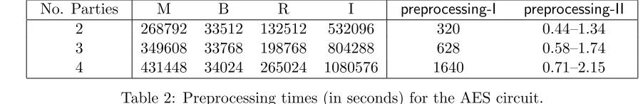
Recall that M is the number of multiplications, B the number of random bits, R the number of random field elements and I the number of input wires. Using the above execution times for the SPDZ protocol we can then estimate the time needed for the two parts of our preprocessing step for the AES circuit. The expected execution times, in seconds, are given in Table 2.
These expected times, due to the methodology of our protocol, are likely to estimate both the latency and throughput amortized over many executions (we only have these times for 2, 3 and 4 parties, since these are the times that have been published for SPDZ offline computations).
No. Parties M B R I preprocessing-I preprocessing-II
2 268792 33512 132512 532096 320 0.44–1.34
3 349608 33768 198768 804288 628 0.58–1.74
4 431448 34024 265024 1080576 1640 0.71–2.15
Table 2: Preprocessing times (in seconds) for the AES circuit.
10Note that unlike [29] and other Yao based techniques we cannot process XOR gates for free. On the other hand
The execution of the online phase of our protocol, when the parties are given their inputs and actually want to compute the function, is very efficient: all that is needed is the evaluation of a garbled circuit based on the data obtained in the offline stage. Specifically, for each gate each party needs to process two input wires, and for each wire it needs to expand n seeds to a length which is n times their original length (where n denotes the number of parties). Namely, for each gate each party needs to compute a pseudorandom function 2n2 times (more specifically, it needs to run 2n key schedulings, and use each key for n encryptions). We examined the cost of implementing these operations for an AES circuit of 33,000 gates when the pseudorandom function is computed using the AES-NI instruction set. The run times for n = 2,3,4 parties were 6.35msec, 9.88msec and 15msec, respectively, for C code compiled using the gcc compiler on a 2.9GHZ Xeon machine. The actual run time, including all non-cryptographic operations, should be higher, but of the same order.
Our run-times estimates compare favourably to several other results on implementing secure computation of AES in a multiparty setting:
• In [10] an actively secure computation of AES using SPDZ took an offline time of over five minutes per AES block, with an online time of around a quarter of a second; that computation used a security parameter of 64 as opposed to our estimates using a security parameter of 128. • In [20] another experiment was shown which can achieve a latency of 50 milliseconds in the
online phase for AES (but no offline times are given).
• In [26] the authors report on a two-party MPC evaluation of the AES circuit using the Tiny-OT protocol; they obtain for 80 bits of security an amortized offline time of nearly three seconds per AES block, and an amortized online time of 30 milliseconds; but the reported non-amortized latency is much worse. Furthermore, this implementation is limited to the case oftwo parties, whereas we obtain security for multiple parties.
Most importantly, all of the above experiments were carried out in a LAN setting where commu-nication latency is very small. However, in other settings where parties are not connected by very fast connections, the effect of the number of rounds on the protocol will be extremely significant. For example, in [10], an arithmetic circuit for AES is constructed of depth 120, and this is then reduced to depth 50 using a bit decomposition technique. Note that if parties are in separate geographical locations, then this number of rounds will very quickly dominate the running time. For example, the latency on Amazon EC2 between Virginia and Ireland is 75ms. For a circuit depth of 50, and even assuming just asingle round per level, the running-time cannot be less than 3750 milliseconds (even if computation takes zero time). In contrast, our online phase has just 2 rounds of communication and so will take in the range of 150 milliseconds. We stress that even on a much faster network with a latency of just 10ms, protocols with 50 rounds of communication will still be slow.
5
Security Proof
we show that our protocol remains secure even ifAismalicious, i.e. is allowed to deviate from the protocol. This second step is performed by showing a reduction from the malicious model to the semi-honest model. In both steps the adversary A is assumed to corrupt parties in the beginning of the execution of the protocol.
We first present some conventions and notations. In both the original BMR protocol and our protocol the players obtain a garbled circuit and a matched set of garbled inputs, they are then able to evaluate the circuit without further interaction. The players evaluate the circuit from the bottom up until they reach the circuit-output wires. I.e., the input wires are said to be at the “bottom” of the circuit, whilst the output wires are at the “top”. In their evaluation the players use the garbled gate g to reveal a single external value for wire c (i.e., Λc, where c is g’s output
wire) together with an appropriate key-vector kc,Λc =k
1
c,Λc, . . . , k
n
c,Λc. There is only one entry in
the garbled gate that can be used to reveal the pair (Λc,kc,Λc); specifically ifg’s input wires area
andbthen entry (2Λa+Λb) in the table of the garbled gate ofgis used (where the entries indices are
0 forAg, 1 for Bg, 2 for Cg and 3 forDg). For each gate we denote the garbled entry for which the
players evaluate that gate as the active entry. The other three entries are denoted as theinactive entries. Similarly we use the term active signal to denote the value Λc that is revealed for some
wirec, and the term active pathfor the set of active signals that have been revealed to the players during the evaluation of the circuit. Recall that in the online phase of our protocol the players exchange the active signal of all the circuit-input wires. We denote by I the set of indices of the players that are under the control of the adversary A, and byxI their inputs to the functionality
(note that in the malicious case these inputs might be different from the inputs that the players have been given originally). In the same manner,J is the set of indices of the honest-parties andxJ
denotes their inputs. (Therefore |I∪J|=n and I∩J =∅.) We denote byW,Win andWout the
sets of all wires, the set of circuit-input wires (a.k.a. attached wires) and the set of circuit-output wires of the circuit C, respectively. We denote the set of gates in the circuit as G={g1, . . . , g|G|}.
Recall that κ is the security parameter.
5.1 Security in the semi-honest model
The basic goal of the proof is to show that there exist a probabilistic polynomial-time procedure, P, whose input is a view sampled from the view distribution of a semi-honest adversary involved in a real execution of the original BMR protocol11, namely REALBMRA in View 1; and its output is
a view from the view distribution of a semi-honest adversary involved in a real execution of our protocol, namely REALOurA (¯x) in View2. Formally, the procedure is defined as
P :{REALBMRA }x¯ → {REALOurA (¯x)}¯x
where ¯x=x1, . . . , xn is the players’ input to the functionality.
In this section we present the procedure P and show that {P(REALBMRA )}x¯ and {REALOurA (¯x)}x¯ are indistinguishable. We then show that the existence of a simulator, SBMR, for A’s view in the execution of the original BMR protocol implies the existence of a simulator SOUR forA’s view in the execution of our protocol. In the following we first describeREALBMRA (View1) andREALOurA (¯x)
(View 2), then we describe the procedureP and prove the mentioned claims.
We are ready to describe the procedureP (Procedure1), which is given a viewREALBMRA that is
sampled from the distribution of the adversary’s views under the input ¯xof the players in the original
11
View 1(The viewREALBMRA ).
For everyi∈Ithe adversary sees the following:
1. Masking shares:Shares of the masking values for all wiresW, i.e. {λiw∈ {0,1} |w∈W}. 2. Masking values for attached wires: The` masking valuesλw of Pi’s attached wires
ware revealed in the clear.
3. Seeds: PlayerPi’s seed values {siw,0, sw,i 1∈ {0,1}κ|w∈W}.
4. Seed extensions: For each seed si
w,b player Pi sees two pseudo-random extensions
G1(si
w,b), G2(siw,b)∈ {0,1}nκ.
In addition the adversary sees:
1. Masking values for output wires: The masking values{λw∈ {0,1} |w∈Wout}.
2. Garbled circuit: For every gate g the garbled table {Ag, Bg, Cg, Dg | g ∈ G} where
Ag, Bg, Cg, Dg∈ {0,1}nκ.
3. Inputs:The input values ¯xI.
4. Active path:For every wirewin the circuit one active signal together with its matched superseed, i.e. (Λw, Sw,Λw), using one entry of the garbled gate. The rest of the values (i.e.
the inactive entries) are indistinguishable from random.
View 2(The viewREALOurA (¯x)).
For everyi∈Ithe adversary sees the following:
1. Masking values for attached wires: The` masking valuesλw of Pi’s attached wires
ware revealed in the clear.
2. Keys.PlayerPi’s random keys{kiw,0, kw,i 1∈Fp|w∈W}.
3. Keys extensions.For every keykiw,b, and for every gate g which wirewenters into, the values
n
Fki
w,b(0k1kg), . . . , Fk i
w,b(0knkg),
Fki
w,b(1k1kg), . . . , Fk i
w,b(1knkg)|w∈W
o
.
In addition the adversary sees:
1. Masking values for output wires: The masking values{λw∈ {0,1} |w∈Wout}.
2. Construction done.The messageconstruction-donebroadcasted by the functionality.
3. Inputs.The input values ¯xI.
4. Open messageThe message open.