Volume 2009, Article ID 749838,10pages doi:10.1155/2009/749838
Research Article
FPGA-Based Real Time, Multichannel Emulated-Digital
Retina Model Implementation
Zsolt V¨or¨osh´azi,
1Zolt´an Nagy,
2and P´eter Szolgay
2, 31Department of Image Processing and Neurocomputing, University of Pannonia, 8200 Veszpr´em, Hungary
2Cellular Sensory and Wave Computing Laboratory, Computer and Automation Institute of HAS, 1111 Budapest, Hungary 3Faculty of Information Technology, P´azm´any P´eter Catholic University, 1083 Budapest, Hungary
Correspondence should be addressed to Zsolt V¨or¨osh´azi,[email protected]
Received 5 September 2008; Accepted 30 January 2009
Recommended by Diego Cabello Ferrer
The function of the low-level image processing that takes place in the biological retina is to compress only the relevant visual information to a manageable size. The behavior of the layers and different channels of the neuromorphic retina has been successfully modeled by cellular neural/nonlinear networks (CNNs). In this paper, we present an extended, application-specific emulated-digital CNN-universal machine (UM) architecture to compute the complex dynamic of this mammalian retina in video real time. The proposed emulated-digital implementation of multichannel retina model is compared to the previously developed models from three key aspects, which are processing speed, number of physical cells, and accuracy. Our primary aim was to build up a simple, real-time test environment with camera input and display output in order to mimic the behavior of retina model implementation on emulated digital CNN by using low-cost, moderate-sized field-programmable gate array (FPGA) architectures.
Copyright © 2009 Zsolt V¨or¨osh´azi et al. This is an open access article distributed under the Creative Commons Attribution License, which permits unrestricted use, distribution, and reproduction in any medium, provided the original work is properly cited.
1. Introduction
The most important sensory organ for both humans and mammals is the retina, which is a sophisticated visual preprocessor system. This well-known part of the eye sends visual information to the higher brain center (visual cortex) across several parallel stacked channels (visual pathway). These parallel operating ganglion cell populations are feature detectors (such as orientation or direction of movement, of form, color, etc.) that are built from a series of complex spatiotemporal transformations generated at different retinal levels.
The retina contains a dense mosaic of light-sensitive cells: the rod and the cone photoreceptors. The photoreceptors are in the deepest layers of the retina, and the light must first pass through rows of other transparent cell layers (ganglion, amacrine, bipolar, and horizontal cells) before reaching the receptors. Functionally, there are these five main cell types in the retina, and in the retinal transmission of information the receptors are the first units and the ganglion cells are the last [1].
Several different retina models have been developed till now: some are low-complexity black-box models [2], while others are high-complexity detailed neuromorphic models [3–5], from which one is described and implemented on FPGA here. The cellular neural/nonlinear network- (CNN-) based neuromorphic model of the vertebrate retina has been continuously improved and refined through the years. First, a number of highly complex space-time transformations were unraveled [4] and only the outer retina functions were explored. The main problems came from the lack of adequate analyzing tools. The detailed framework of mammalian retinal modeling via two-dimensional and multilayer CNN was published in [5], which provides us suitable model back-ground to the real-time implementation. Definition of the neuromorphic model elements was based on retinal anatomy and electrophysiology measurements. The complexity of this channel-based model is moderate enough, therefore, it can be adapted to different hardware implementations using the CNN computational paradigm.
chips, and emulated-digital hardware (ASIC or FPGA) [6,
7]. However, the determination of the model parameters requires very high computing power and accurate solution. On one hand, using the complex cell analog VLSI chips, only the basic building blocks of the retina model can be implemented [6]. On the other hand, the software simulators provide high flexibility, but low computing speed [8, 9], hence simulating these detailed neuromorphic structures require powerful workstations, but simulations still require several hours or days to complete.
By using an emulated-digital CNN universal machine (CNN-UM) architecture on FPGA [10] we can overcome the limitations of the analog VLSI CNN chips such as a few numbers of layers (1-2), relatively small array size (128×128), difficulties with implementing nonlinear templates, and low accuracy (limited to 6-7 bit).
The emulated digital architectures based on CNN computational paradigm can be used very efficiently for two-dimensional, spatiotemporal signal processing, solving partial differential equations (PDEs) and state equations of complex dynamical systems [11] as well.
A neuromorphic two dimensional but multilayer retina model was successfully developed and tested comparing the computed and measured values. By using reconfigurable FPGAs, we could handle the inherently multilayer struc-ture of a retina model, and the parameters and values can be represented with scalable accuracy [10, 11]. The previously elaborated single-channel model [7] was extended to a multichannel one with higher hardware requirements and optimizations. The complete real-time system (about 30 frame/sec) based on FPGA, video camera, and monitor was built up to verify the model’s behavior and to analyze the effect of parameter accuracy.
Considering the structure of this paper, in Section 2, we show the computational background of the mammalian retina model. Details about the optimized Falcon processor and the distributed arithmetic unit of the multilayer retina model architecture are introduced inSection 3. InSection 4
real-time image processing test systems are presented while in Section 5 the device utilization and the speedup on different FPGA architectures are analyzed. In Section 6
our results are compared to the original neurobiological measurements and the implemented model is demonstrated by an example. Finally, some conclusions are drawn in
Section 7.
2. Background: The Mammalian Retina Model
2.1. Governing Equations. The basic building blocks of the biological retina model are the abstract neurons which are organized into two-dimensional layers [2]. The model seems to be complex in one hand, but can be decomposed into multi-layer CNN structure and can be implemented on a parallel processing array. The main components of the abstract neuron are the cell body, the synapses, and the output transfer function. The cell body has a first- or second-order dynamics, which is described by the following differential equations deduced from [5]:
τl
nx˙nl = −xln+
kl∈Sn
Cλ n,klxnl,kl+
∀m∈Sy1
kl∈Sm fr
nm
Gσ
nm,klyml
+
∀m∈Sy2
xnmr +
∀m∈Sy3
xnmr −rxdnm
−sxnj,
(1)
τnjx˙nj = −xnj+xln, (2)
yl n= fno
xl
n
, (3)
Cλ
n=λ
⎡ ⎢ ⎣
1 2 1
2 −12 2
1 2 1
⎤ ⎥
⎦, (4)
Gσnm,i j=
1
∀k,lGσnm(k,l)
ge−√i2+j2/σ
, (5)
⎡ ⎢ ⎢ ⎣
Gσ−1,−1 Gσ−1,0 Gσ−1,1
Gσ0,−1 Gσ0,0 Gσ0,1
Gσ1,−1 Gσ1,0 Gσ1,1
⎤ ⎥ ⎥
⎦, (6)
where
(i)xl
nandx
j
nare the states of the second-order abstract
neuron,
(ii) yis the nonlinear output of the abstract neuron,
(iii)τlandτjare the time constants of the different layers
in various retina channels (see [5]),
(iv) fr and fo are the receptor and the output transfer
function,
(v) Sn and Sm are the local neighborhood of the neuron,
(vi)C is the diffusion type template (see (4)), receptive field- (RF-) type spatial weighting at intralayer synapses,
(vii)λ is the coupling parameter (space constant) of a given layer,
(viii)G is the Gauss-type template (see (5) and its matrix-form (6)), RF-type spatial weighting at intra-/ interlayer synapses, wheregis the gain parameter of the receptor
(ix)σ is the sigma (spatial property) parameter of the receptor,
(x) Sy1, Sy2, and Sy3 are the plain, delayed, and desensi-tized receptor set, respectively,
(xi)r is the ratio parameter, ands is the feedback gain (strength of the interaction).
Subsequent layers supply the input of the next layer through synapses. The abstract neuron has receptors to implement these synapses. The three different types of recep-tors are plain, delayed, and desensitizing. The differential equations of the receptors are the following:
τr
nmx˙rnm= −xnmr +
kl∈Sm
fr nm
Gσ
nm,klylm
,
τnmd x˙dnm= −xdnm+xrnm,
Cone Cone2
Horizontal
Input
Amacrine FB
Ganglion
Amacrine
FF
Model Function
Transduction
Blurring
Difference
Broadcast, timing
Output Bipolar inhibition desensitization
Bipolar inhibition
receptor
Bipolar excitation desensitization
Bipolar excitation
receptor
τ τ
τ
τ
τ
τ
τ
τ
τ
τ
λ
λ
λ
λ λ λ
λ
+
−
Figure1: General neuromorphic structure of the light-adapted mammalian retina model. The horizontal lines represent different layers showing their proper cell names and functions. The vertical dashed arrows denote the inhibitory synapses while continuous arrows show the excitatory synapses. These connections can be varied for each specific retina channels. Each diffusion layer can be associated with a diffusion constant (called space constant) and a local time constant.
where
(i)xr
nm and xdnm are the states of the receptor and the
desensitized receptor,
(ii)τr andτd are the delay and the desensitizing speed
(time constants) of the receptor.
2.2. Requirements. The light-adapted mammalian retina model consists of several main parts. These main parts are the outer retina model and the different ganglion models. The outer retina is a 3-layered uniform block (generally called outer plexiform layer), which transforms the input stimulus to the different, parallel ganglion models (channels).
The ganglion models contain three functional blocks: the excitation pattern generator, the inhibitory subsystem, and the ganglion cell model. This middle abstraction-level model can be transformed into a low-level multilayer CNN structure as shown inFigure 1. Each layer has its own time constant and connection weights. The interlayer connections are zero neighborhood neuron to neuron links that have linear- or rectifier-type, nonlinear transfer functions.
Constructing a single channel of the retina model at least 10 vertically stacked CNN layers are required. The whole structure cannot be directly implemented on the two-layer complex-cell analog VLSI CNN-UM chip (e.g., CACE1k) [6]. Additionally, the size of the array is just 32×32 cells, which is not sufficient for most of practical applications where larger image size is required (e.g., 174× 144 sized cell array in QCIF format). Another analog VLSI implementation is a handy camera exploration device implemented on a stand-alone Bi-I system [12], which is capable of computing four retina channels in real time. However, the relatively low accuracy and moderate array size of these analog chips (128×128) do not make it possible to
utilize their high computing power during the correct model building and parameter tuning steps of the retina modeling.
3. Objective: Retina Model Implementation
on FPGA
The elaborated Falcon-multilayer (ML) emulated-digital CNN-UM architecture based on FPGA can be used to emulate a globally connected multilayer CNN network. It has a modular structure, for example, the number of layers and processors elements, the size and the number of templates can be adjusted moreover, the bit widths of state, constant, and template values are configurable [10]. Large number of these parameters makes it easy to synthesize the Falcon architecture, which is optimal for the retina channel computations. The control unit can be tailored to these configuration parameters.
The hardware complexity of Falcon-ML core increases in quadratic manner as the number of layers is increased. In the simplest case, for modeling one channel of the retina at least 10 layers should be emulated which means that 100 inter and intralayer connections and 300 multipliers (in case of nearest neighborhood templates where 3 multipliers are used to compute the template operation in 3 clock cycles) are required. Although implementing such a huge arithmetic unit of the single-channel retina model is already possible on the latest available reconfigurable FPGA chip, it consumes a lot of dedicated resources, therefore, some optimizations are required. This complex arithmetic unit can compute the derivatives and update the cell’s state value in one clock cycle but it requires pipelining to achieve high clock speeds.
Input
memory unit
Mixer
unit StateIn1
TmpIn
Template
memory
Arithmetic core
Arithmetic core
StateOut1
State
memory unit
Mixer
unit StateInp
StateOutp
TempIni
First/last MemIn
Input
Control unit Enable
DataValidIn /Out TmpSel
Figure 2: The structure of the optimized multilayer Falcon-ML architecture (pdenotes the number of layers).
Shift
r
e
g
.
Iterate
StateOut
Old state Input from memory unit
Diffusion type
Gauss type
Intr a-layer
Figure 3: The block level structure of the optimized arithmetic core.
a one or two row-high belt from the given layer. Using this structure the I/O requirements of the processor are reduced topload andpstore operations per cell update. The optimized template memory contains only the parameters which are necessary to perform the computations, while the modified arithmetic units make efficient computation of the different type multilayer dynamics possible.
If we consider the different specific channels of the mammalian retina model, most of the interlayer links are zero, some of them are zero neighborhood templates and only a few feedback connections require a nearest neighbor template [5]. Additionally, the diffusion- and Gauss-type templates (see (4) and (6)) are symmetrical, which makes further optimizations possible. The block level structure of the optimized arithmetic unit is shown inFigure 3. To reduce the clock cycle time of the arithmetic unit, pipeline technique is used. According to (1), (2), and (7) the computation of the derivatives can be divided into the following three parts:
(i) computation with the zero neighborhood (intra- and interlayer) connections,
(ii) computation with the diffusion-type template, (iii) computation with the Gauss-type templates.
Each layer has a separated and optimized arithmetic core which is connected to the mixer and memory units of the
Reg. Reg. xi+1,j+1xi+1,j−1 xi−1,j+1xi−1,j−1 xi,j+1xi,j−1 xi+1,j xi−1,j xi,j
+ + + + +
+ +
+
<<1
<<1
<<2
λ
−
∗
kl∈Sn Cλ
n,klxnl,kl
Figure4: Structure of the optimized arithmetic unit to compute the diffusion-type template (pipeline registers are not shown for simplicity).
other layers according to the existing connections between the layers (seeFigure 1). The structure of the arithmetic unit is shown inFigure 3.
The simplest element of the arithmetic unit is the intralayer block, which computes the inter- and intralayer zero neighborhood connections. This unit contains one multiplier for each connection, and the multiplied values are summed by an adder tree.
Due to the symmetry properties of the diffusion-type template (see (4)), the computation can be performed by the optimized circuit shown inFigure 4.
Multiplication with 2 and−12 is carried out by shifting operations and only one multiplier is required to compute the 3 × 3 template operation. This solution reduces the number of required multipliers from 3 to 1. Additionally, the number of clock cycles required to compute a new value is also reduced from 3 to 1 clock cycle, which significantly increases the computing performance of the processor.
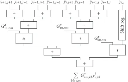
The Gaussian template (see (6)) is also symmetrical but the ratio of the coefficient values is not an integer number. Therefore, at first the equally weighted state values are summed then these partial results are multiplied; finally the multiplied values are summed again. By using this optimized circuit shown inFigure 5, the number of multipliers is still three but the length of the computation cycle is reduced to one clock cycle.
The optimized Falcon-ML processor uses the discretized Forward-Euler method to compute the dynamics in each layer of the retina model. The Iterate block of the arithmetic unit (inFigure 3) sums the computed parts of the derivative and computes the new state value of each cell. The time-step valuehis restricted to be an integer power of two. This method allows us to perform the multiplication withhby shifts and does not require an additional multiplier.
Shift
r
e
g
.
yi+1,j+1 yi+1,j−1 yi−1,j+1yi−1,j−1 yi,j+1yi,j−1 yi+1,jyi−1,j yi,j
+ + + +
+ +
+ ∗
Gσ11,nm Gσ10,nm
Gσ00,nm
∗ ∗
+
kl∈Sm Gσnm,klyln,kl
Figure5: Structure of the optimized arithmetic unit to compute the Gauss-type template (pipeline registers are not shown for simplicity).
XC2V6000
FPGA Input
stimulus
RC2000 board
USB
PCI-X 64 Retina
model
Monitor
VGA out
Host PC
XRM-CL
module Output
Camera Input stimulus Camera
LINK Web
camera
66 MHz
CPU/MB
M
M
M
M
M
M
Figure6: Test environment for RC2000 prototyping board.
time compared to the conventional HDL-based RTL level approaches, where the entire model hierarchy should be treated.
4. Real-Time Test Environments
The proposed specialized Falcon-ML architecture with single-channel and the extended multichannel model were implemented both on the RC2000 prototyping board (in
Figure 6) from Agility Inc. [13] and on the XUPV2P development board (inFigure 7) from Digilent Inc. [14].
The PCI-based RC2000 board contains a Virtex-II FPGA (XC2V6000) and 24 MB ZBT SSRAM memory, which is organized in six 36-bit wide independent banks [13]. Indi-rectly, a simple web camera can be connected to the host PC with a USB cable and it can communicate with the RC2000 board across the PCI-64 bit/66 MHz bus. Alternatively, using the XRM CameraLINK module, we can attach an external digital camera directly to the standard XRM-CL interface. This test environment is represented inFigure 6.
Our another experimental system was the XUPV2P prototyping board based on Virtex-II Pro FPGA (XC2VP30) which is supplied with 256 MB DDR SDRAM memory [14]. Using the Digilent VDEC1 video decoder add-on board [15] makes it possible to connect an NTSC camera directly to the FPGA board and it sends input video frames to the processor with 25 fps, shown inFigure 7.
XC2VP30
FPGA
XUPV2P board
Retina model
Monitor VGA out
DDR SDRAM
DIMM
Output
VGA DAC
Video decoder
board (VDEC1)
Camera Input stimulus
Figure7: XUPV2P-based experimental system.
Table1: General single-channel retina model requirements and available resources on different FPGAs.
Device utilization and speed
1-channel (10 layer) retina model @ 22 bit
Available on XC2V6000
Available on XC2VP30
Available on XC5SX240T
Num. of occupied slices
8496 33 792 13 696 37440∗
Num. of
BRAMs 69 144 136 516
∗
Num. of
MULTs 35 144 136 1056
∗
Max. Core
Freq. [MHz] — 220 280 550
∗Virtex-5 FPGAs are differently organized: a slice contains four 6-input
LUT, 4-bit carry logic, and four registers; size of the Virtex-5 BRAM is 36 Kbit and the multipliers (DSP48E slice) are 25×18-bit wide.
In both cases a monitor displays the computed results of the various channels of retina model.
5. Device Utilization and Performance
The available resources and the device utilizations for some different FPGA processors are summarized in Table 1. The single-channel retina model implementation consume large amount from the available chip resources, even at 22-bit state precision. This is the required accuracy to provide qualitatively correct responses for input stimulus (as we will see in Section7).
Architecture of the Xilinx Virtex-5 devices is different from the previous Virtex families, therefore, area require-ments of the retina model implementation is smaller on these devices. Additionally, these new devices have considerably more general logic and dedicated resources. Due to these considerations, the number of implementable Falcon-ML processor elements can be increased, which makes it possible to emulate multiple retina-channels in video real time.
0 20 40 60 80 100
R
esour
ce
oc
cupancy
(slic
es)
(%)
18 20 22 24 26 28 30 32 34 36
Precision (bit) XC2VP30
XC2V6000 XC5VSX240T
Figure8: Logical resource (slice) requirements on different FPGAs.
0 20 40 60 80 100
R
esour
ce
oc
cupancy
(%)
18 20 22 24 26 28 30 32 34 36
Precision (bit) XC2VP30 BRAM18k
XC2V6000 BRAM18k XC5VSX240T BRAM36k XC2VP30 MULT18×18 XC2V6000 MULT18×18 XC5VSX240T MULT25×18
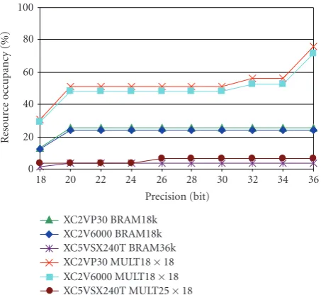
Figure9: Dedicated resource (multiplier, block-ram) requirements on different FPGAs.
have similar amount of dedicated resources and about 50% of Mult18×18 components and about 25% of BRAM18k blocks are required for the implementation as shown in
Figure 9, considering the qualitatively correct 22–24 bit state precision.
If we use the state-of-the-art Virtex-5 SX240T, DSP-specialized FPGA, only a small fraction of the available resources are used at 22–24 bit precision: 8.2% of slices, 3.4% of BRAM36Ks block memories, and 4% of DSP48E multipliers are utilized.
The number of the implementable processor cores is strongly related to the resource occupancies for different reconfigurable Xilinx chips. This is summarized inFigure 10. By using our Virtex-II Pro30 and Virtex-II 6000 moderate-sized, low-cost (below $1.000) FPGAs only 1-2 processor core(s) of the general, single-channel, multilayer retina
0 5 10 15 20 25
N
u
mber
of
pr
oc
essors
18 20 22 24 26 28 30 32 34 36
Precision (bit) XC2VP30
XC2V6000 XC5VSX240T
Figure10: Number of implementable processor cores on different FPGAs.
model can be implemented at acceptable precision (∼22– 24 bit) that provides qualitatively correct output results. The main limitations in these two cases are the moderate number of dedicated multiplier (signed, 18-bit 2’s complement MULT18×18) resources.
However, constructing a specific retina model for each different channel instead of using the general model, we can save additional resources by eliminating some unwanted connections. On the currently available largest Virtex-5 FPGA (XC5VSX240T) which is optimized for DSP- and memory-intensive applications even 17 Falcon-ML proces-sor cores can be implemented to speed up the compu-tations [16]. In this case, the number of available logical slices determines the number of implementable Falcon-ML processor elements. Since Virtex-5 family contains a huge number of 25×18-bit wide DSP48E multiplier blocks (1056), therefore, in the optimized arithmetic core of the Falcon-ML processor only a few number of dedicated multiplier blocks are required at the 22–24 bit precision. For this reason, more (or all) channels of the CNN-based mammalian retina model can be emulated simultaneously.
The performance of the elaborated architecture is scaled linearly according to the number of the processors. Comput-ing performance compared to the speed of an Intel Core2 Duo T7200 [17] microprocessor running on 2 GHz clock frequency is shown in Figure 11. During the comparison proprietary-optimized software was run on the micropro-cessors which directly solved (1), (2), and (7) using the discretized Forward-Euler method.
The results of the general retina model show that even in the case of the moderate sized XC2V6000 FPGA at least 150 times higher computing performance can be achieved at the adequate 22–24-bit precision compared to the software simulation. If the state-of-the-art specialized XC5VSX240T FPGA is used, the computations can be carried out more than 3200 times faster.
0 400 800 1200 1600 2000 2400 2800 3200 3600 4000 4400
Speed-up
18 20 22 24 26 28 30 32 34 36
Precision (bit) XC2VP30
XC2V6000 XC5VSX240T
Figure11: Performance of different implementations compared to an Intel Core2 Duo processor running on 2 GHz.
BRAM memories on a given FPGA. In case of single-channel retina model and without using external memory the maximum size of the processed images can reach 64×64 on Virtex-II and Virtex-II Pro FPGA, while about 256 × 256 on the Virtex-5 FPGA architecture. To process high-resolution images the external onboard memory is required to store the state values of the retina model. So the processing time will be about an order of magnitude slower due to the memory bandwidth limitation.
The high computing performance of the largest available XC5VSX240T FPGA makes video real-time emulation of multiple retina channels possible. The clock frequency of the architecture is 550 MHz and only one clock cycle is required to compute a new cell value. The cumulative performance of the 17 implementable processor cores at qualitatively acceptable 22–24 bit precision can reach 9.35 billion cell iteration/sec. The high performance of this processor is capable of computing 256×256-sized cell array in real-time (at 30 frames/sec) and the different channels of the retina can be emulated by using 2−7millisecond timestep.
Additionally, the large number of implementable Falcon processors makes it also possible to emulate more than one specific channel of the retina. In this case only one three-layered, uniform outer retina block is required and the processor is extended to emulate additional excitation, inhibition, and ganglion blocks. The modular structure of the memory and the arithmetic unit makes this extension possible easily. The Handel-C [13] high-level hardware description language makes implementation process and testing of the new processor much faster and simpler than the conventional RTL-based HDL level approaches.
Unfortunately, expansion of the neuromorphic retina model with any new layer increases the required I/O bandwidth significantly and several clock cycles are necessary to load the state values and save the results. Although the arithmetic unit can update a value in every clock cycle this high computing power cannot be utilized because several dummy cycles must be inserted until the I/O operations
1E−04 1E−03 1E−02 1E−01 1E+ 00
Er
ro
r
10 12 14 16 18 20 22 24 26 28 30 32 34 36 Precision (bit)
OffBriskL OnBriskTrN OffBriskTr
OnSluggish OnBist
Figure12: Differences of the 64 bit floating-point and the fixed-point result of the various retina channels.
are carried out. Due to the architectural properties of the moderate sized Virtex-II and Virtex-II Pro FPGAs the memory units must be configured 1024 element-wide. In most cases much smaller cell array size is required hence the memory unit is also underutilized. To improve the utilization of the memory and the arithmetic unit virtual processors are implemented. These virtual processors are chained one after another and each of them works on different Forward-Euler iteration. In case of the memory unit the data of the different virtual memory units are stored on subsequent addresses. Similarly the arithmetic unit is used by the different virtual arithmetic units in subsequent clock cycles. Implementation of the virtual processors incurs minimal overhead in area. In most cases only shift registers are required, which can be very efficiently implemented on the FPGA. By using virtual processors the utilization of the memory and the arithmetic unit can be improved which results in higher performance.
6. Accuracy and Results
Performance of the processor can be significantly improved by decreasing the computational precision, but low precision gives inaccurate solution. We should find a balance between computing precision and solution accuracy. The results of the different fixed-point computations are compared to the 64-bit floating point results. Not knowing the exact analytical solution of a complex numerical problem, the double precision floating point implementation is considered as the accurate solution. The absolute maximum difference between the different solutions is represented inFigure 12.
A simple test case is computed by using different computing precision to approximate the accuracy of the results as it can be seen inFigure 13.
Noise Response
20 40 60 80 100 120 10 20 30 40 50 60 0 0.1 0.2 0.3 0.4 0.5 0.6 0.7 0.8 0.9 1
Input stimulus
Neurobiological
measurements Floatin(64 bit) gpoint
Excitation
Inhibition
Ganglion
14 bit 24 bit 32 bit
20 40 60 80 100 120 10 20 30 40 50 60 0.1 0.2 0.3 0.4 0.5 0.6 0.7 0.8 0.9
20 40 60 80 100 120 10 20 30 40 50 60 0.1 0.2 0.3 0.4 0.5 0.6 0.7 0.8 0.9
20 40 60 80 100 120 10 20 30 40 50 60 0.1 0.2 0.3 0.4 0.5 0.6 0.7 0.8 0.9
20 40 60 80 100 120
20 40 60 80 100 120 20 40 60 80 100 120 20 40 60 80 100 120 20 40 60 80 100 120 10 20 30 40 50 60 0.1 0.2 0.3 0.4 0.5 0.6 0.7 0.8 0.9 10 20 30 40 50 60 0.1 0.2 0.3 0.4 0.5 0.6 0.7 0.8 0.9 10 20 30 40 50 60 0.1 0.2 0.3 0.4 0.5 0.6 0.7 0.8 0.9 10 20 30 40 50 60 0.1 0.2 0.3 0.4 0.5 0.6 0.7 0.8 0.9 10 20 30 40 50 60 0.1 0.2 0.3 0.4 0.5 0.6 0.7 0.8 0.9 10 20 30 40 50 60 0.1 0.2 0.3 0.4 0.5 0.6 0.7 0.8 0.9 10 20 30 40 50 60 0.1 0.2 0.3 0.4 0.5 0.6 0.7 0.8 0.9 10 20 30 40 50 60 0.1 0.2 0.3 0.4 0.5 0.6 0.7 0.8 0.9 10 20 30 40 50 60 0.1 0.2 0.3 0.4 0.5 0.6 0.7 0.8 0.9 20 40 60 80 100 120 20 40 60 80 100 120 20 40 60 80 100 120 20 40 60 80 100 120
Figure 13: Accuracy of our solution at different bit widths (in case of OffBrisk-Linear channel type) compared to the results of neurobiological measurements derived from [5]. The simple test input is a commonly used flashed square stimulus. The time runs horizontally while space is on the vertical axes. The total examined time period is 2 seconds, where the flashing white stimulus is “turned-on” for 1 second.
precision is required while qualitatively correct results can already be obtained by using 22–24 bit precision. Input test stimulus of the model is the commonly used white flashed square, where the square is white for 1 second and uniform gray for 1 second. During the simulation the responses of different channels are computed by an FPGA of our experimental systems and finally the results are projected on the monitor. The spatiotemporal distributions of activity at different computing precisions are shown inFigure 13. The results qualitatively reproduce the inhibition, excitation, and spiking patterns of the neurobiological measurements for the flashed square stimulus.
The main goal of our emulated-digital implementation is to reproduce the results of neurobiological measurements and we are not focused on solving the computation of the dynamics as accurately as possible. The integration step size (h) is tightly related to the timing parameters (τ) and to the accuracy of the solution. Proper settings of theτparameters are deduced from [5] (the details are shown in Table 1). The timing parameters can be of very different values of the subsequent layers within a unique retina channel and the smallest one will determine the value of the time-step.
Several higher order numerical methods are examined during the computation of the CNN dynamics and summa-rized in [18,19]. On the one hand, if we use the higher-order Runge-Kutta (RK-4) formula the step-size can be doubled compared to the Forward-Euler method, but it requires four
times more computations as the explicit Euler formula. It will imply that the Falcon architecture based on the higher-order Runge Kutta method requires four times more multiplier blocks, therefore, the area occupancy on FPGA will also be significantly increased. So this method is not worth to be implemented on an FPGA in the case of the retina model computations, because four-time larger area, which results in four-time smaller performance, is required to halve the number of steps.
On the other hand, during our computations the Forward-Euler method is used which is commonly applied in the calculations of the CNN dynamics. Although the Forward-Euler method employed in the Falcon-ML architec-ture computes the dynamic with smaller and fixed step-size as the Runge Kutta-4 method and it has a limited precision, the computations will be numerically stable if the step-size is selected carefully.
7. Example
Input
ON-BiStratified
OFF-BriskLinear
Excitation Inhibition
(a)
(b)
(c)
Ganglion
Figure 14: In this example two different (ON-, and OFF-type) retina channels are computed in video real-time by using our experimental system.
channels is shown in Figure 14. The size of the processed picture is set to 64×64, while time-step value h is adjusted as 2−7 millisecond. Row (a) shows the natural input stimulus captured by a camera. Row (b) denotes the first retina channel called OnBiStratified, while Row (c) demonstrates the second channel called OffBrisk-Linear. Each column represents the biologic name of the cells: bipolar excitation, inhibition, and ganglion cell output (spiking), respectively.
8. Conclusion
Our experimental systems with extended emulated-digital CNN-UM architecture based on the optimized Falcon-ML processor core were successfully designed to solve the state equations of the multilayer retina model. Due to the modular structure, it rapidly provides implementable specialized processors to emulate different retina models and multiple retina channels on the low-cost (referring to the ASIC implementations), moderate-sized FPGA prototyping boards as well. The computing precision of the processor is configurable in wide range making a trade-off between area and performance. Even using moderate precision (at 22– 24 bit) the fixed-point results are very close to the floating-point result, which is considered as analytical result. If the precision is increased further to 30-bit, the accuracy of the fixed-point solution is comparable to the accuracy of the floating-point result. This provides for using our proposed architecture during the rapid model building and parameter tuning steps of various retina modeling where fast and accurate solution of the model is required.
On the currently available largest FPGAs these computa-tions can be performed approximately three orders of magni-tude faster than an Intel Core2 Duo microprocessor running at 2 GHz clock frequency. On the proposed architecture the cumulated performance of the Falcon-ML processors makes video real-time emulation possible in case of multiple retina-channels and large-sized (e.g., 256×256) cell arrays.
To sum it up, our proposed emulated-digital implemen-tation on FPGA, based on CNN framework of the mam-malian retina model, is capable of reproducing qualitatively the same full set of space-time activity patterns as the living retina in response to the different input stimulus.
References
[1] A. Valberg,Light Vision Color, John Wiley & Sons, New York, NY, USA, 2005.
[2] M. Meister and M. J. Berry II, “The neural code of the retina,”
Neuron, vol. 22, no. 3, pp. 435–450, 1999.
[3] B. Roska and F. Werblin, “Vertical interactions across ten parallel, stacked representations in the mammalian retina,”
Nature, vol. 410, no. 6828, pp. 583–587, 2001.
[4] F. Werblin and A. Jacobs, “Using CNN to unravel space-time processing in the vertebrate retina,” inProceedings of the 3rd IEEE International Workshop on Cellular Neural Networks and Their Applications (CNNA ’94), pp. 33–40, Rome, Italy, December 1994.
[5] D. B´alya, B. Roska, T. Roska, and F. S. Werblin, “A CNN frame-work for modeling parallel processing in a mammalian retina,”
International Journal of Circuit Theory and Applications, vol. 30, no. 2-3, pp. 363–393, 2002.
[6] Cs. Rekeczky, T. Serrano-Gotarredona, T. Roska, and A. Rodr´ıguez-V´azquez, “A stored program 2nd order/3-layer complex cell CNN-UM,” in Proceedings of the 6th IEEE International Workshop on Cellular Neural Networks and Their Applications (CNNA ’00), pp. 213–217, Catania, Italy, May 2000.
[7] Z. Nagy, Z. V¨or¨osh´azi, and P. Szolgay, “An emulated digital retina model implementation on FPGA,” inProceedings of the 9th IEEE International Workshop on Cellular Neural Networks and Their Applications (CNNA ’05), pp. 278–281, Hsinchu, Taiwan, May 2005.
[8] D. B´alya, B. Roska, T. Roska, and F. S. Werblin, “A CNN model framework and simulator for biological sensory systems,” in
Proceedings of the 15th European Conference on Circuit Theory and Design (ECCTD ’01), pp. 357–360, Espoo, Finland, August 2001.
[9] “RefineC—Receptive Field Network Calculus reference man-ual (version 2.5),”http://lab.analogic.sztaki.hu/Candy/refinec UsersGuide.pdf.
[10] Z. Nagy and P. Szolgay, “Configurable multilayer CNN-UM emulator on FPGA,”IEEE Transactions on Circuits and Systems I, vol. 50, no. 6, pp. 774–778, 2003.
[11] Z. Nagy and P. Szolgay, “Numerical solution of a class of PDEs by using emulated digital CNN-UM on FPGAs,” inProceedings of the 16th European Conference on Circuits Theory and Design (ECCTD ’03), vol. 2, pp. 181–184, Krak ´ow, Poland, September 2003.
[12] D. Balya and B. Roska, “A handy retina exploration device,” in
Proceedings of the 9th IEEE International Workshop on Cellular Neural Networks and Their Applications (CNNA ’05), pp. 223– 226, Hsinchu, Taiwan, May 2005.
[13] Agility Design Solutions Inc., 2008,http://www.agilityds.com. [14] Digilent Inc. XUPV2P, “Virtex-II Pro Development System,”
2008,http://www.digilentinc.com/XUPV2P.
[15] Digilent Inc., “VDEC-1 Video Decoder Add-on Board,” 2008,
http://www.digilentinc.com.
[17] “Intel Core2 Duo and Intel Core2 Solo for Intel Centrino Duo Processor Technology—Specification,” November 2007,
http://www.intel.com/design/core2duo/documentation.htm. [18] Z. Szl´avik, D. B´alya, and T. Roska, “Properties of the adaptive
integration formula to compute the CNN dynamic equations,” in Proceedings of the 16th European Conference on Circuits Theory and Design (ECCTD ’03), vol. 1, pp. 105–108, Krak ´ow, Poland, September 2003.